EP0866265A2 - Wärmesenke - Google Patents
Wärmesenke Download PDFInfo
- Publication number
- EP0866265A2 EP0866265A2 EP98302021A EP98302021A EP0866265A2 EP 0866265 A2 EP0866265 A2 EP 0866265A2 EP 98302021 A EP98302021 A EP 98302021A EP 98302021 A EP98302021 A EP 98302021A EP 0866265 A2 EP0866265 A2 EP 0866265A2
- Authority
- EP
- European Patent Office
- Prior art keywords
- core
- heat sink
- fins
- recess
- sink according
- Prior art date
- Legal status (The legal status is an assumption and is not a legal conclusion. Google has not performed a legal analysis and makes no representation as to the accuracy of the status listed.)
- Withdrawn
Links
Images

Classifications
-
- F—MECHANICAL ENGINEERING; LIGHTING; HEATING; WEAPONS; BLASTING
- F21—LIGHTING
- F21V—FUNCTIONAL FEATURES OR DETAILS OF LIGHTING DEVICES OR SYSTEMS THEREOF; STRUCTURAL COMBINATIONS OF LIGHTING DEVICES WITH OTHER ARTICLES, NOT OTHERWISE PROVIDED FOR
- F21V29/00—Protecting lighting devices from thermal damage; Cooling or heating arrangements specially adapted for lighting devices or systems
- F21V29/50—Cooling arrangements
- F21V29/70—Cooling arrangements characterised by passive heat-dissipating elements, e.g. heat-sinks
- F21V29/74—Cooling arrangements characterised by passive heat-dissipating elements, e.g. heat-sinks with fins or blades
-
- F—MECHANICAL ENGINEERING; LIGHTING; HEATING; WEAPONS; BLASTING
- F28—HEAT EXCHANGE IN GENERAL
- F28F—DETAILS OF HEAT-EXCHANGE AND HEAT-TRANSFER APPARATUS, OF GENERAL APPLICATION
- F28F1/00—Tubular elements; Assemblies of tubular elements
- F28F1/10—Tubular elements and assemblies thereof with means for increasing heat-transfer area, e.g. with fins, with projections, with recesses
- F28F1/12—Tubular elements and assemblies thereof with means for increasing heat-transfer area, e.g. with fins, with projections, with recesses the means being only outside the tubular element
- F28F1/34—Tubular elements and assemblies thereof with means for increasing heat-transfer area, e.g. with fins, with projections, with recesses the means being only outside the tubular element and extending obliquely
-
- H—ELECTRICITY
- H01—ELECTRIC ELEMENTS
- H01J—ELECTRIC DISCHARGE TUBES OR DISCHARGE LAMPS
- H01J61/00—Gas-discharge or vapour-discharge lamps
- H01J61/02—Details
- H01J61/52—Cooling arrangements; Heating arrangements; Means for circulating gas or vapour within the discharge space
Definitions
- This invention relates to a heat sink, particularly a heat sink to dissipate heat from a lamp, camera or the like.
- Heat sinks to dissipate heat from lamps and the like are well known and it is an object of the present invention to provide a heat sink that can improve heat dissipation from a source while maintaining or reducing the overall size of the heat sink.
- the invention enables an increase in the effective surface area available for heat dissipation within a given overall volume.
- the invention provides a heat sink comprising a cylindrical core of thermally conducting material and an array of spaced, heat dissipating fins extending around and attached to the outer surface of the core, the fins being disposed at an angle to the longitudinal axis of the core and the heat sink containing a recess to accommodate a portion of the body requiring heat dissipation whereby the body can be in contact with the core.
- the recess is preferably shaped and sized to receive the body closely to ensure good contact between the body and the core to maximise the heat dissipation effect.
- the core is preferably of copper although other good thermal conductors, e.g. aluminium or silver, may be used if desired.
- the recess may be in the core itself.
- the recess may extend for the whole of the axial length of the core, i.e. the core may be an annulus, and the recess is in fact a through passage, or it may extend only partially along the length of the core.
- the core may be a solid cylindrical bar of, e.g. copper, having an integral hollow annular portion at one end to define the recess.
- the recess may be defined by the fins only.
- the fins may extend axially beyond the core to define the recess.
- the only direct contact between the lamp or other body and the core is an end to end contact at the inner end of the recess and there may also be direct contact between the lamp and the fins.
- the recess defined by the fins shares a longitudinal axis with the core and hence extends centrally in the heat sink.
- the fins which are preferably of the same material as the core, may be attached to the core by any suitable means.
- adhesives or low temperature soldering or high temperature brazing may be used for copper and adhesives or vacuum brazing may be used for aluminium.
- Suitable adhesives include resin-based adhesives, e.g. epoxy resins.
- correspondingly angled slots may, for example, be machined on the surface of the core, each slot to receive an edge of a fin.
- the core may be formed by casting with appropriate slots. It may be preferable to cast the core and fins or a proportion of the fins, e.g. alternate fins, as an integral body. Thus, for example, a repeating array of fin then slot then fin may be cast with alternate separate fins then being adhered into the slots.
- the angle of the fins to the longitudinal axis of the core may be, for example from 30° to 75°, especially from 40° to 60°.
- the fins have an axial extent (relative to the core) equal to the length of the core and are co-extensive axially with the core.
- this is not essential and, if desired, the fins may extend beyond one or both ends of the core. Indeed, as indicated above, this arrangement in which the fins extend beyond one end of the core forms one particular embodiment of the invention when the core is a solid bar.
- the heat sink may, of course, be used in conjunction with other means conventionally used to dissipate the heat transmitted through the fins, e.g. forced draughts of air.
- the invention is described herein with particular reference to lamps, it is applicable to a variety of other heat sources, e.g. lasers, studio lighting and, particularly, any cylindrically-shaped heat source.
- the recess will normally be cylindrical although other shapes of recess may be provided, if desired, to match other shapes of heat sources.
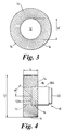
- heat sink 10 comprises a cylindrical core 12 of copper having attached to its outer surface an array of fins 14. Fins 14 lie at an angle ⁇ ° to the longitudinal axis of core 12. Although in principle ⁇ may be any number between 0° and 90°, as indicated above, it is preferred to be from 30° to 75°. The edges of the fins in contact with the core lie in slots (not shown) into which they have been adhered.
- fins 14 extend longitudinally beyond the core 12 and form a recess 16 axially contiguous with the core.
- a lamp 18 has a body portion 18A and a lens 20. Body portion 18A is of size to extend into the recess and closely fill it. The end face of the lamp body portion inside the recess is in contact with end face 12A of the core 12 to ensure good heat transference from the lamp to the core and the fins.
- a core of about 76 mm diameter "d" may have from 50 to 120 fins attached to its outer surface and the overall diameter "D" of the heat sink may be about 150 mm and its length "L” about 55 mm, the copper core being about 25 to 30 mm in length.
- the dimensions and fin numbers and angles can vary widely depending on the specific circumstances and performance requirements.
Landscapes
- Engineering & Computer Science (AREA)
- General Engineering & Computer Science (AREA)
- Physics & Mathematics (AREA)
- Geometry (AREA)
- Thermal Sciences (AREA)
- Mechanical Engineering (AREA)
- Cooling Or The Like Of Semiconductors Or Solid State Devices (AREA)
- Arrangement Of Elements, Cooling, Sealing, Or The Like Of Lighting Devices (AREA)
- Non-Portable Lighting Devices Or Systems Thereof (AREA)
Applications Claiming Priority (3)
| Application Number | Priority Date | Filing Date | Title |
|---|---|---|---|
| GB9705984A GB2323434B (en) | 1997-03-22 | 1997-03-22 | Heat sink |
| GB9705984 | 1997-03-22 | ||
| US09/045,786 US6196298B1 (en) | 1997-03-22 | 1998-03-23 | Heat sink |
Publications (2)
| Publication Number | Publication Date |
|---|---|
| EP0866265A2 true EP0866265A2 (de) | 1998-09-23 |
| EP0866265A3 EP0866265A3 (de) | 2000-08-16 |
Family
ID=26311240
Family Applications (1)
| Application Number | Title | Priority Date | Filing Date |
|---|---|---|---|
| EP98302021A Withdrawn EP0866265A3 (de) | 1997-03-22 | 1998-03-18 | Wärmesenke |
Country Status (3)
| Country | Link |
|---|---|
| US (1) | US6196298B1 (de) |
| EP (1) | EP0866265A3 (de) |
| GB (1) | GB2323434B (de) |
Cited By (4)
| Publication number | Priority date | Publication date | Assignee | Title |
|---|---|---|---|---|
| GB2431041A (en) * | 2005-10-08 | 2007-04-11 | David Horsfield | Lamp heat sink |
| DE10196917B4 (de) * | 2000-11-20 | 2009-11-05 | Intel Corporation, Santa Clara | Hochleistungsrippenaufbau für eine luftgekühlte Wärmeableitvorrichtung |
| EP2086305A3 (de) * | 2008-02-01 | 2010-04-14 | Neng Tyi Precision Industries Co., Ltd. | Wärmeableitendes Element und Kühlkörper damit |
| US20100181889A1 (en) * | 2009-01-16 | 2010-07-22 | Light Prescriptions Innovators, Llc | Heat sink with helical fins and electrostatic augmentation |
Families Citing this family (11)
| Publication number | Priority date | Publication date | Assignee | Title |
|---|---|---|---|---|
| US6360816B1 (en) * | 1999-12-23 | 2002-03-26 | Agilent Technologies, Inc. | Cooling apparatus for electronic devices |
| US6971383B2 (en) * | 2001-01-24 | 2005-12-06 | University Of North Carolina At Chapel Hill | Dry powder inhaler devices, multi-dose dry powder drug packages, control systems, and associated methods |
| JP3686005B2 (ja) * | 2001-03-30 | 2005-08-24 | 山洋電気株式会社 | ヒートシンクを備えた冷却装置 |
| US20030111944A1 (en) * | 2001-12-13 | 2003-06-19 | Vildana Jahic | Bulb attachment for temperature limited environment |
| US6695045B2 (en) * | 2002-03-19 | 2004-02-24 | Mitac Technology Corporation | Bladed heat sink |
| US20040118552A1 (en) * | 2002-12-24 | 2004-06-24 | Wen-Shi Huang | Heat-dissipating device |
| US6937473B2 (en) * | 2003-06-30 | 2005-08-30 | Intel Corporation | Heatsink device and method |
| US20050257912A1 (en) * | 2004-01-12 | 2005-11-24 | Litelaser Llc | Laser cooling system and method |
| TWM257092U (en) * | 2004-05-07 | 2005-02-11 | Liang-Fu Huang | Skived-fin type heat radiator |
| US7972037B2 (en) | 2008-11-26 | 2011-07-05 | Deloren E. Anderson | High intensity replaceable light emitting diode module and array |
| US11056330B2 (en) * | 2018-12-21 | 2021-07-06 | Thermo Finnigan Llc | Apparatus and system for active heat transfer management in ESI ion sources |
Family Cites Families (9)
| Publication number | Priority date | Publication date | Assignee | Title |
|---|---|---|---|---|
| US2289984A (en) * | 1940-07-12 | 1942-07-14 | Westinghouse Electric & Mfg Co | Air cooler for power tubes |
| US2680009A (en) * | 1953-02-25 | 1954-06-01 | Rca Corp | Cooling unit |
| DE3151838A1 (de) * | 1981-12-29 | 1983-07-21 | BBC Aktiengesellschaft Brown, Boveri & Cie., 5401 Baden, Aargau | Kuehlvorrichtung fuer scheibenfoermige halbleiterelemente |
| JPS61189657A (ja) * | 1985-02-18 | 1986-08-23 | Fuji Photo Film Co Ltd | 半導体素子温度制御装置 |
| US4715438A (en) * | 1986-06-30 | 1987-12-29 | Unisys Corporation | Staggered radial-fin heat sink device for integrated circuit package |
| US4785216A (en) * | 1987-05-04 | 1988-11-15 | Ilc Technology, Inc. | High powered water cooled xenon short arc lamp |
| US5561338A (en) * | 1995-04-13 | 1996-10-01 | Ilc Technology, Inc. | Packaged arc lamp and cooling assembly in a plug-in module |
| EP0751339A3 (de) * | 1995-06-30 | 1998-05-06 | CUNNINGHAM, David W. | Beleuchtungseinrichtung mit gegossenem Reflektor |
| US5785116A (en) * | 1996-02-01 | 1998-07-28 | Hewlett-Packard Company | Fan assisted heat sink device |
-
1997
- 1997-03-22 GB GB9705984A patent/GB2323434B/en not_active Expired - Fee Related
-
1998
- 1998-03-18 EP EP98302021A patent/EP0866265A3/de not_active Withdrawn
- 1998-03-23 US US09/045,786 patent/US6196298B1/en not_active Expired - Fee Related
Cited By (5)
| Publication number | Priority date | Publication date | Assignee | Title |
|---|---|---|---|---|
| DE10196917B4 (de) * | 2000-11-20 | 2009-11-05 | Intel Corporation, Santa Clara | Hochleistungsrippenaufbau für eine luftgekühlte Wärmeableitvorrichtung |
| GB2431041A (en) * | 2005-10-08 | 2007-04-11 | David Horsfield | Lamp heat sink |
| EP2086305A3 (de) * | 2008-02-01 | 2010-04-14 | Neng Tyi Precision Industries Co., Ltd. | Wärmeableitendes Element und Kühlkörper damit |
| US20100181889A1 (en) * | 2009-01-16 | 2010-07-22 | Light Prescriptions Innovators, Llc | Heat sink with helical fins and electrostatic augmentation |
| US8354779B2 (en) * | 2009-01-16 | 2013-01-15 | Light Prescriptions Innovators Llc | Heat sink with helical fins and electrostatic augmentation |
Also Published As
| Publication number | Publication date |
|---|---|
| GB2323434A (en) | 1998-09-23 |
| US6196298B1 (en) | 2001-03-06 |
| GB2323434B (en) | 2000-09-20 |
| EP0866265A3 (de) | 2000-08-16 |
| GB9705984D0 (en) | 1997-05-07 |
Similar Documents
| Publication | Publication Date | Title |
|---|---|---|
| US6196298B1 (en) | Heat sink | |
| CA2478802C (en) | Light source with heat transfer arrangement | |
| US9322517B2 (en) | Non-glare reflective LED lighting apparatus with heat sink mounting | |
| US7740380B2 (en) | Solid state lighting apparatus utilizing axial thermal dissipation | |
| EP1774222B1 (de) | Beleuchtungsvorrichtung mit lampeneinheit und reflektor | |
| US9157598B2 (en) | Heat managing device | |
| US20080007954A1 (en) | Heat-Dissipating Structure For LED Lamp | |
| US6145585A (en) | Motor housing with invertedly disposed T-grooves for quick dissipation of heat | |
| WO2004003974A3 (en) | Composite heat sink with metal base and graphite fins | |
| US7837358B2 (en) | Light-emitting diode module with heat dissipating structure | |
| JP5877597B1 (ja) | ヒートパイプ冷却シングル型高輝度led前照灯 | |
| KR101272748B1 (ko) | 차량용 엘이디 헤드램프 | |
| US9234646B2 (en) | Non-glare reflective LED lighting apparatus with heat sink mounting | |
| US10378751B2 (en) | Heat sink, corresponding lighting device and method of use | |
| US9206975B2 (en) | Non-glare reflective LED lighting apparatus with heat sink mounting | |
| US12222095B1 (en) | Lightweight powerful LED light for drones | |
| US6008568A (en) | Heatsinked lamp assembly | |
| KR102247144B1 (ko) | 방열장치 | |
| FI981927A0 (fi) | Lämmönvaihtoyksikkö ja käyttö | |
| JPH088493A (ja) | 半導体レーザ装置における放熱構造 | |
| JP2004037720A (ja) | バンドルファイバ | |
| GB2073483A (en) | Cooling lamps | |
| CN211600278U (zh) | 一种灯具 | |
| JP2542250Y2 (ja) | ヒートシンク | |
| JP5877598B1 (ja) | ヒートパイプ冷却ダブル型高輝度led前照灯 |
Legal Events
| Date | Code | Title | Description |
|---|---|---|---|
| PUAI | Public reference made under article 153(3) epc to a published international application that has entered the european phase |
Free format text: ORIGINAL CODE: 0009012 |
|
| AK | Designated contracting states |
Kind code of ref document: A2 Designated state(s): AT BE CH DE DK ES FI FR GR IE IT LI LU MC NL PT SE |
|
| AX | Request for extension of the european patent |
Free format text: AL;LT;LV;MK;RO;SI |
|
| PUAL | Search report despatched |
Free format text: ORIGINAL CODE: 0009013 |
|
| AK | Designated contracting states |
Kind code of ref document: A3 Designated state(s): AT BE CH DE DK ES FI FR GB GR IE IT LI LU MC NL PT SE |
|
| AX | Request for extension of the european patent |
Free format text: AL;LT;LV;MK;RO;SI |
|
| 17P | Request for examination filed |
Effective date: 20010216 |
|
| AKX | Designation fees paid |
Free format text: AT BE CH DE DK ES FI FR GR IE IT LI LU MC NL PT SE |
|
| RAP1 | Party data changed (applicant data changed or rights of an application transferred) |
Owner name: IMI MARSTON LIMITED |
|
| RAP1 | Party data changed (applicant data changed or rights of an application transferred) |
Owner name: HS MARSTON AEROSPACE LIMITED |
|
| 17Q | First examination report despatched |
Effective date: 20040330 |
|
| GRAP | Despatch of communication of intention to grant a patent |
Free format text: ORIGINAL CODE: EPIDOSNIGR1 |
|
| STAA | Information on the status of an ep patent application or granted ep patent |
Free format text: STATUS: THE APPLICATION IS DEEMED TO BE WITHDRAWN |
|
| 18D | Application deemed to be withdrawn |
Effective date: 20060728 |