EP0866509A2 - Instrument portatif comportant un compartiment de pile à verrouillage de sécurité - Google Patents
Instrument portatif comportant un compartiment de pile à verrouillage de sécurité Download PDFInfo
- Publication number
- EP0866509A2 EP0866509A2 EP98301590A EP98301590A EP0866509A2 EP 0866509 A2 EP0866509 A2 EP 0866509A2 EP 98301590 A EP98301590 A EP 98301590A EP 98301590 A EP98301590 A EP 98301590A EP 0866509 A2 EP0866509 A2 EP 0866509A2
- Authority
- EP
- European Patent Office
- Prior art keywords
- probe
- instrument
- battery
- cover
- connector
- Prior art date
- Legal status (The legal status is an assumption and is not a legal conclusion. Google has not performed a legal analysis and makes no representation as to the accuracy of the status listed.)
- Withdrawn
Links
- 239000000523 sample Substances 0.000 claims abstract description 79
- 238000012360 testing method Methods 0.000 claims abstract description 8
- 238000009434 installation Methods 0.000 description 1
- 239000000463 material Substances 0.000 description 1
- 239000002184 metal Substances 0.000 description 1
- 230000001681 protective effect Effects 0.000 description 1
- 238000005201 scrubbing Methods 0.000 description 1
Images


Classifications
-
- H—ELECTRICITY
- H05—ELECTRIC TECHNIQUES NOT OTHERWISE PROVIDED FOR
- H05K—PRINTED CIRCUITS; CASINGS OR CONSTRUCTIONAL DETAILS OF ELECTRIC APPARATUS; MANUFACTURE OF ASSEMBLAGES OF ELECTRICAL COMPONENTS
- H05K5/00—Casings, cabinets or drawers for electric apparatus
- H05K5/0086—Casings, cabinets or drawers for electric apparatus portable, e.g. battery operated apparatus
-
- G—PHYSICS
- G01—MEASURING; TESTING
- G01D—MEASURING NOT SPECIALLY ADAPTED FOR A SPECIFIC VARIABLE; ARRANGEMENTS FOR MEASURING TWO OR MORE VARIABLES NOT COVERED IN A SINGLE OTHER SUBCLASS; TARIFF METERING APPARATUS; MEASURING OR TESTING NOT OTHERWISE PROVIDED FOR
- G01D11/00—Component parts of measuring arrangements not specially adapted for a specific variable
- G01D11/24—Housings ; Casings for instruments
-
- G—PHYSICS
- G01—MEASURING; TESTING
- G01R—MEASURING ELECTRIC VARIABLES; MEASURING MAGNETIC VARIABLES
- G01R1/00—Details of instruments or arrangements of the types included in groups G01R5/00 - G01R13/00 and G01R31/00
- G01R1/02—General constructional details
- G01R1/04—Housings; Supporting members; Arrangements of terminals
-
- H—ELECTRICITY
- H01—ELECTRIC ELEMENTS
- H01M—PROCESSES OR MEANS, e.g. BATTERIES, FOR THE DIRECT CONVERSION OF CHEMICAL ENERGY INTO ELECTRICAL ENERGY
- H01M50/00—Constructional details or processes of manufacture of the non-active parts of electrochemical cells other than fuel cells, e.g. hybrid cells
- H01M50/20—Mountings; Secondary casings or frames; Racks, modules or packs; Suspension devices; Shock absorbers; Transport or carrying devices; Holders
- H01M50/204—Racks, modules or packs for multiple batteries or multiple cells
- H01M50/207—Racks, modules or packs for multiple batteries or multiple cells characterised by their shape
- H01M50/213—Racks, modules or packs for multiple batteries or multiple cells characterised by their shape adapted for cells having curved cross-section, e.g. round or elliptic
-
- G—PHYSICS
- G01—MEASURING; TESTING
- G01R—MEASURING ELECTRIC VARIABLES; MEASURING MAGNETIC VARIABLES
- G01R15/00—Details of measuring arrangements of the types provided for in groups G01R17/00 - G01R29/00, G01R33/00 - G01R33/26 or G01R35/00
- G01R15/12—Circuits for multi-testers, i.e. multimeters, e.g. for measuring voltage, current, or impedance at will
-
- Y—GENERAL TAGGING OF NEW TECHNOLOGICAL DEVELOPMENTS; GENERAL TAGGING OF CROSS-SECTIONAL TECHNOLOGIES SPANNING OVER SEVERAL SECTIONS OF THE IPC; TECHNICAL SUBJECTS COVERED BY FORMER USPC CROSS-REFERENCE ART COLLECTIONS [XRACs] AND DIGESTS
- Y02—TECHNOLOGIES OR APPLICATIONS FOR MITIGATION OR ADAPTATION AGAINST CLIMATE CHANGE
- Y02E—REDUCTION OF GREENHOUSE GAS [GHG] EMISSIONS, RELATED TO ENERGY GENERATION, TRANSMISSION OR DISTRIBUTION
- Y02E60/00—Enabling technologies; Technologies with a potential or indirect contribution to GHG emissions mitigation
- Y02E60/10—Energy storage using batteries
Definitions
- This invention relates to hand held electronic instruments, and more particularly to instruments having replaceable batteries and removable electrical leads.
- DMMs digital multimeters
- DMMs may have on-board power supplied by conventional replaceable batteries.
- a set of removable probes is plugged into receptacles in the DMM, and is extended to contact electrical nodes on the device.
- DMMs may be used for testing high voltage devices that may pose a safety hazard to a user.
- circuitry in the DMM may also be "hot," or at a high voltage.
- earlier DMMs have provided battery covers that resist removal when probes are connected.
- a flat battery cover overlays the probe receptacles, and has holes registered with the receptacles.
- the probes are normally removed before the lid is removed, preventing any exposed circuitry in the DMM from being at a high voltage potential when the batteries are replaced.
- Such configurations are limited in their effectiveness.
- an electronic instrument with a housing having a battery compartment.
- the housing has a probe connector oriented on a probe axis, so that a probe may be connected to the instrument via the connector for interfacing with a device under test.
- a removable battery cover encloses the battery compartment, and has a probe aperture registered with the probe connector, so that a probe may be connected when the battery cover is installed.
- the battery cover is constrained against movement along the probe axis.
- the battery cover may contain a conductive safety element necessary to complete a circuit between the battery and other components in the instrument, so that the batteries are capable of delivering power only when the cover is properly installed.
- Figure 1 is perspective view of an instrument according to a preferred embodiment of the invention.
- Figure 2 is an exploded view of the instrument of Figure 1 with the battery cover and probes removed.
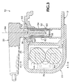
- Figure 3 is a sectional lateral view taken along line 3-3 of Figure 1.
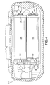
- Figure 4 is a sectional end view taken along line 4-4 of Figure 1.
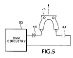
- Figure 5 shows, partly in schematic form and partly in pictorial form, the electrical circuit connection/disconnection feature of the invention.
- FIG. 1 shows a hand held digital multi meter (DMM) 10 having a housing 12 with a display screen 14 on a front surface 16 of the housing near an upper end 20, and a box-shaped battery cover 22 encompassing a lower end 24 of the housing.
- the housing defines three probe connector apertures 26, each of which includes an electrical contact connected to internal instrument circuitry (not shown), and is configured for interfacing with a conventional electrical probe 30.
- the battery cover 22 has the shape of an open ended box, with the open end facing and receiving the lower end 24 of the housing.
- the cover has a bottom panel 32 and a flange or sleeve portion 34 extending from the bottom panel.
- the sleeve portion encompasses a lower end of the housing.
- the sleeve portion includes a front panel 35 defining three probe holes 36 that register with the housing's connector apertures 26 when the cover is installed. Because the cover holes 36 are spaced apart from the rim 40 of the cover, a rigid web 42 of cover material will encounter a probe inserted deeply into the aperture 26, to prevent removal of the cover.
- a pair of batteries 44 are received in a battery receptacle 46 at the lower end 20 of the housing. Access for battery replacement is permitted only when the cover 22 is removed.
- the flange portion 34 of the battery cover 22 closely encompasses the lower end of the housing 12, so that an interior surface 50 ofthe front panel 35 is in direct sliding contact with a front surface of the housing.
- the close fit constrains the cover's relative motion to one degree of freedom: sliding along the long axis 51 of the instrument. Neither lateral translation nor rotation about any axis is permitted by the close fit.
- a probe connector 52 is positioned within the hole 26, and includes an elongated cylindrical outer plastic sleeve 54 and a conductive inner sleeve 56.
- an elongated conductive mandrel 60 makes ohmic contact with sleeve 56, and a protective plastic shield 62 extending longer than the mandrel encompasses the connector sleeve 54.
- the rigid body of the probe extends along a connector axis 64 coaxial with the connector, beyond the front surface of the housing and cover. This ensures that the cover is locked in place as long as the probe is installed.
- the connector axes are perpendicular to the long axis of the instrument.
- the pair of conventional AA size batteries is contained within the receptacle 46 in side-by-side relation, with their positive terminals pointing in opposite directions.
- a positive contact 66 and negative contact 70 are mounted to the housing to contact the adjacent end terminals of the respective batteries.
- the contacts are mounted side-by-side.
- a frame 71 restrains the battery ends, and provides openings for electrical connections.
- a circular hole 72 receives the positive terminal of the battery nearer the front surface, and a wider V-shaped opening 74 exposes the negative terminal of the other battery for electrical contact.
- a conductive bridge 76 is mounted to the interior of the cover 22.
- the bridge is a metal leaf spring having two flexible arms, each contacting a terminal of a respective one of the batteries when the cover is installed on the housing.
- the hole 72 and opening 74 permit the arms to make direct electrical contact.
- the arms are curved away from the batteries at their free ends to present a smooth, convex surface, facilitating the repeated installation and removal of the cover, with the arms sliding freely across the housing and battery surfaces.
- the constrained axial motion of the cover relative to the housing is along an axis parallel to the long axis of the instrument and to the planar surfaces of contact between the bridge arms and the battery terminals.
- the bridge is mounted securely to a boss 80 in the interior of the cover.
- the conductive bridge may be mounted to the housing adjacent to but spaced apart from the battery terminals, with a non-conductive actuator element on the cover deflecting the bridge into contact with the batteries only when the cover is fully installed.
- FIG. 5 illustrates an electrical circuit employing safety device 76.
- DMM circuitry 85 is coupled in series with a pair of batteries 44 and safety device 76.
- safety device 76 is mounted to the interior of cover 22. When cover 22 is removed, safety device 76 moves in the direction of the dotted arrow, disconnects the batteries from the DMM circuitry, and thereby prevents operation of the DMM with the cover removed.
Landscapes
- Physics & Mathematics (AREA)
- General Physics & Mathematics (AREA)
- Engineering & Computer Science (AREA)
- Microelectronics & Electronic Packaging (AREA)
- Chemical & Material Sciences (AREA)
- Chemical Kinetics & Catalysis (AREA)
- Electrochemistry (AREA)
- General Chemical & Material Sciences (AREA)
- Battery Mounting, Suspending (AREA)
Applications Claiming Priority (2)
| Application Number | Priority Date | Filing Date | Title |
|---|---|---|---|
| US820300 | 1997-03-18 | ||
| US08/820,300 US5834935A (en) | 1997-03-18 | 1997-03-18 | Hand held instrument with safety locked battery compartment |
Publications (2)
| Publication Number | Publication Date |
|---|---|
| EP0866509A2 true EP0866509A2 (fr) | 1998-09-23 |
| EP0866509A3 EP0866509A3 (fr) | 1999-07-14 |
Family
ID=25230421
Family Applications (1)
| Application Number | Title | Priority Date | Filing Date |
|---|---|---|---|
| EP98301590A Withdrawn EP0866509A3 (fr) | 1997-03-18 | 1998-03-04 | Instrument portatif comportant un compartiment de pile à verrouillage de sécurité |
Country Status (5)
| Country | Link |
|---|---|
| US (1) | US5834935A (fr) |
| EP (1) | EP0866509A3 (fr) |
| JP (1) | JPH10282139A (fr) |
| KR (1) | KR19980080132A (fr) |
| CN (1) | CN1209541A (fr) |
Cited By (5)
| Publication number | Priority date | Publication date | Assignee | Title |
|---|---|---|---|---|
| GB2451918A (en) * | 2007-08-14 | 2009-02-18 | Fluke Corp | Multimeter front panel and case top |
| EP2023704A3 (fr) * | 2007-08-09 | 2010-05-05 | Fujitsu Limited | Appareil électronique |
| EP2293085A1 (fr) * | 2009-09-07 | 2011-03-09 | Conrad Electronic SE | Appareil de mesure |
| CN104569556A (zh) * | 2015-02-05 | 2015-04-29 | 马宁 | 一种便携式电压表 |
| EP3486616A1 (fr) * | 2017-11-16 | 2019-05-22 | Yokogawa Electric Corporation | Appareil de mesure |
Families Citing this family (14)
| Publication number | Priority date | Publication date | Assignee | Title |
|---|---|---|---|---|
| USD418437S (en) * | 1998-11-16 | 2000-01-04 | Tektronix, Inc. | Hand held test and measurement device |
| USD442101S1 (en) | 2000-05-17 | 2001-05-15 | Spx Corporation | Digital automobile tester |
| US20040253997A1 (en) * | 2003-06-16 | 2004-12-16 | Spx Corporation | Wireless test data transmission apparatus and method |
| US6980417B2 (en) * | 2003-11-13 | 2005-12-27 | Ken-Chao Chang | Meter with concealed probe receiving deck |
| US7802318B2 (en) * | 2006-10-24 | 2010-09-28 | Chun-Nan Chen | Helmet having cooling fan device |
| JP2008111733A (ja) * | 2006-10-31 | 2008-05-15 | Hioki Ee Corp | 電気計測機器 |
| USD723401S1 (en) | 2013-06-19 | 2015-03-03 | Danaher (Shanghai) Industrial Instrumentation Technologies R&D Co., Ltd. | Digital multimeter |
| EP3181306A1 (fr) * | 2015-12-17 | 2017-06-21 | HILTI Aktiengesellschaft | Machine-outil iii sur batterie |
| CN105572431A (zh) * | 2016-01-29 | 2016-05-11 | 苏州莱测检测科技有限公司 | 一种防护性好的电子电压表测量杆 |
| CN107769292A (zh) * | 2016-08-23 | 2018-03-06 | 錞镱科技股份有限公司 | 具有充电切换保护机制的量表 |
| CN108700626B (zh) * | 2017-11-28 | 2021-09-10 | 深圳市隐秀科技有限公司 | 一种检测装置及具有该检测装置的便携式电子设备 |
| CN110514887A (zh) * | 2018-05-22 | 2019-11-29 | 日置电机株式会社 | 携带式测量器 |
| USD946430S1 (en) * | 2020-07-28 | 2022-03-22 | Chauvin Arnoux | Power energy logger |
| USD1054889S1 (en) | 2023-02-10 | 2024-12-24 | Chauvin Arnoux | Insulation resistance tester |
Family Cites Families (7)
| Publication number | Priority date | Publication date | Assignee | Title |
|---|---|---|---|---|
| US3881961A (en) * | 1973-08-02 | 1975-05-06 | Motorola Inc | Battery housing |
| US4176315A (en) * | 1978-05-11 | 1979-11-27 | Sunnarborg Earl D | Miniature electrical voltage and continuity tester with circuit compartment and test lead compartment casing |
| ZA832204B (en) * | 1982-04-05 | 1983-12-28 | Y S Securities Ltd | Electrical switchgear |
| FR2637153B1 (fr) * | 1988-09-27 | 1993-03-26 | Itt Composants Instr | Appareil electrique a compartiment de pile perfectionne |
| DE4104884A1 (de) * | 1991-02-18 | 1992-08-20 | Braun Ag | Elektrogeraet |
| US5287013A (en) * | 1992-02-03 | 1994-02-15 | Motorola, Inc. | Battery compartment safety interlock |
| DE4438239C1 (de) * | 1994-10-26 | 1996-06-05 | Mueller & Weigert | Batteriebetriebenes Meßgerät, insbesondere Zangenanlegegerät |
-
1997
- 1997-03-18 US US08/820,300 patent/US5834935A/en not_active Expired - Fee Related
-
1998
- 1998-03-04 EP EP98301590A patent/EP0866509A3/fr not_active Withdrawn
- 1998-03-11 KR KR1019980008097A patent/KR19980080132A/ko not_active Withdrawn
- 1998-03-16 JP JP10065584A patent/JPH10282139A/ja active Pending
- 1998-03-18 CN CN98108766A patent/CN1209541A/zh active Pending
Cited By (12)
| Publication number | Priority date | Publication date | Assignee | Title |
|---|---|---|---|---|
| EP2023704A3 (fr) * | 2007-08-09 | 2010-05-05 | Fujitsu Limited | Appareil électronique |
| US7817407B2 (en) | 2007-08-09 | 2010-10-19 | Fujitsu Limited | Electronic apparatus |
| GB2451918A (en) * | 2007-08-14 | 2009-02-18 | Fluke Corp | Multimeter front panel and case top |
| US7911200B2 (en) | 2007-08-14 | 2011-03-22 | Fluke Corporation | Digital multimeter having case panel structure |
| GB2451918B (en) * | 2007-08-14 | 2012-04-18 | Fluke Corp | Digital multimeter having case panel structure |
| GB2485501A (en) * | 2007-08-14 | 2012-05-16 | Fluke Corp | Digital Multimeter Case Panel |
| GB2485501B (en) * | 2007-08-14 | 2012-07-11 | Fluke Corp | Digital multimeter having case panel structure |
| US8466671B2 (en) | 2007-08-14 | 2013-06-18 | Fluke Corporation | Digital multimeter having a case and a separate panel structure |
| EP2293085A1 (fr) * | 2009-09-07 | 2011-03-09 | Conrad Electronic SE | Appareil de mesure |
| CN104569556A (zh) * | 2015-02-05 | 2015-04-29 | 马宁 | 一种便携式电压表 |
| EP3486616A1 (fr) * | 2017-11-16 | 2019-05-22 | Yokogawa Electric Corporation | Appareil de mesure |
| US11009377B2 (en) | 2017-11-16 | 2021-05-18 | Yokogawa Electric Corporation | Measuring apparatus |
Also Published As
| Publication number | Publication date |
|---|---|
| JPH10282139A (ja) | 1998-10-23 |
| KR19980080132A (ko) | 1998-11-25 |
| CN1209541A (zh) | 1999-03-03 |
| US5834935A (en) | 1998-11-10 |
| EP0866509A3 (fr) | 1999-07-14 |
Similar Documents
| Publication | Publication Date | Title |
|---|---|---|
| US5834935A (en) | Hand held instrument with safety locked battery compartment | |
| US6042400A (en) | Power supply housing with foldable blades | |
| JPH0617356Y2 (ja) | 静電気防止コネクター | |
| US7056134B2 (en) | Attachable/detachable probing tip system for a measurement probing system | |
| US4211456A (en) | Magnetic electrical connectors | |
| US7753732B2 (en) | Shield connector structure | |
| US5540596A (en) | Electric plug for supplying current to electric appliances | |
| JP2012502277A (ja) | ローブブロックアセンブリ | |
| US9935402B2 (en) | Electrical connector assembly having connector bodies and removable caps | |
| JP2002304934A (ja) | 静電除去機構を有するダイアル装置及び該ダイアル装置を備えた電子機器 | |
| US20210075133A1 (en) | Automotive booster cable system | |
| GB2248973A (en) | Portable type memory device | |
| US6280258B1 (en) | Arrangements relating to electrical connections between apparatuses containing electrical circuitry | |
| US6078184A (en) | Measuring tip unit | |
| JP3789415B2 (ja) | 着脱式アンテナ装置 | |
| US4297635A (en) | Watthour meter and battery retaining apparatus therefor | |
| US7114956B2 (en) | Isolated BNC connector with replaceable bayonet shell | |
| US20050263317A1 (en) | Inverted strain relief | |
| CN212392702U (zh) | 一种充电盒及充电系统 | |
| CN218940160U (zh) | 气溶胶生成装置及设有其的气溶胶生成系统 | |
| US4300113A (en) | Fused electric plug | |
| JP2005286851A (ja) | 電子機器 | |
| JP2024079129A (ja) | 液面レベルセンサ | |
| JPH0973955A (ja) | メタルシールドカバーおよびシールド構造 | |
| JP2006310041A (ja) | コンセント用プレート、及びコンセント |
Legal Events
| Date | Code | Title | Description |
|---|---|---|---|
| PUAI | Public reference made under article 153(3) epc to a published international application that has entered the european phase |
Free format text: ORIGINAL CODE: 0009012 |
|
| AK | Designated contracting states |
Kind code of ref document: A2 Designated state(s): AT BE CH DE DK ES FI FR GB GR IE IT LI LU MC NL PT SE |
|
| AX | Request for extension of the european patent |
Free format text: AL;LT;LV;MK;RO;SI |
|
| PUAL | Search report despatched |
Free format text: ORIGINAL CODE: 0009013 |
|
| AK | Designated contracting states |
Kind code of ref document: A3 Designated state(s): AT BE CH DE DK ES FI FR GB GR IE IT LI LU MC NL PT SE |
|
| AX | Request for extension of the european patent |
Free format text: AL;LT;LV;MK;RO;SI |
|
| AKX | Designation fees paid | ||
| REG | Reference to a national code |
Ref country code: DE Ref legal event code: 8566 |
|
| STAA | Information on the status of an ep patent application or granted ep patent |
Free format text: STATUS: THE APPLICATION IS DEEMED TO BE WITHDRAWN |
|
| 18D | Application deemed to be withdrawn |
Effective date: 20000115 |