EP0866536A2 - Disjoncteur à courant de défaut pour tous-courants - Google Patents
Disjoncteur à courant de défaut pour tous-courants Download PDFInfo
- Publication number
- EP0866536A2 EP0866536A2 EP98104716A EP98104716A EP0866536A2 EP 0866536 A2 EP0866536 A2 EP 0866536A2 EP 98104716 A EP98104716 A EP 98104716A EP 98104716 A EP98104716 A EP 98104716A EP 0866536 A2 EP0866536 A2 EP 0866536A2
- Authority
- EP
- European Patent Office
- Prior art keywords
- current
- signal branch
- circuit breaker
- direct current
- signal
- Prior art date
- Legal status (The legal status is an assumption and is not a legal conclusion. Google has not performed a legal analysis and makes no representation as to the accuracy of the status listed.)
- Withdrawn
Links
Images


Classifications
-
- H—ELECTRICITY
- H02—GENERATION; CONVERSION OR DISTRIBUTION OF ELECTRIC POWER
- H02H—EMERGENCY PROTECTIVE CIRCUIT ARRANGEMENTS
- H02H3/00—Emergency protective circuit arrangements for automatic disconnection directly responsive to an undesired change from normal electric working condition with or without subsequent reconnection ; integrated protection
- H02H3/26—Emergency protective circuit arrangements for automatic disconnection directly responsive to an undesired change from normal electric working condition with or without subsequent reconnection ; integrated protection responsive to difference between voltages or between currents; responsive to phase angle between voltages or between currents
- H02H3/32—Emergency protective circuit arrangements for automatic disconnection directly responsive to an undesired change from normal electric working condition with or without subsequent reconnection ; integrated protection responsive to difference between voltages or between currents; responsive to phase angle between voltages or between currents involving comparison of the voltage or current values at corresponding points in different conductors of a single system, e.g. of currents in go and return conductors
- H02H3/33—Emergency protective circuit arrangements for automatic disconnection directly responsive to an undesired change from normal electric working condition with or without subsequent reconnection ; integrated protection responsive to difference between voltages or between currents; responsive to phase angle between voltages or between currents involving comparison of the voltage or current values at corresponding points in different conductors of a single system, e.g. of currents in go and return conductors using summation current transformers
- H02H3/332—Emergency protective circuit arrangements for automatic disconnection directly responsive to an undesired change from normal electric working condition with or without subsequent reconnection ; integrated protection responsive to difference between voltages or between currents; responsive to phase angle between voltages or between currents involving comparison of the voltage or current values at corresponding points in different conductors of a single system, e.g. of currents in go and return conductors using summation current transformers with means responsive to DC component in the fault current
Definitions
- the invention relates to a residual current circuit breaker for universal current with at least one summation current transformer and a downstream evaluation circuit for one signal branch suitable for pulse current and / or direct current.
- Residual current circuit breakers for so-called all-current, i.e. For AC, pulse current from rectifier circuits and for Direct current, for example from DE 3 543 985 A1 and known from DE 3 543 948 B1. They usually have two Total current transformer.
- the first summation current transformer transforms Pulse currents and alternating currents for further processing in the pulse current branch. If a limit is exceeded a trigger coil is energized and the shutdown is triggered.
- the direct current can be detected with the second summation current transformer be because its secondary winding has an inductive resistance represents. This resistance is with direct current or a DC component in the primary circuit through the Saturation effect in the core material reduced.
- AC voltage therefore leads to a changed AC in the winding, which in the DC signal branch is processed and possibly to excite one second trigger coil leads.
- the known arrangements are comparatively complex.
- the object of the invention is therefore a simpler residual current circuit breaker to propose for all-current.
- the object is achieved in that a single Total current transformer with a toroid alike as Pulse current converter for the pulse current signal branch and as a direct current signal generator serves for the direct current signal branch and that Means for the selective feeding of pulse current and / or DC current available in the respective evaluation signal branch are.
- the means for selective feeding can be a clock, preferably a square wave generator, or a filter be.
- a summation current transformer in Alternating timing as a pulse current converter and as a DC signal generator is working.
- the clock generator controls each the time blocking and release of the signals for the Pulse current signal branch and the direct current signal branch.
- the release of the signal path to the pulse current signal branch is Infeed of the rectangular generator on the second secondary winding of the total current transformer blocked and thus equally no signal transfer to the DC signal branch possible.
- Pulse current signal branch feeding the square wave generator to the second secondary winding of the summation current transformer and released the signal to the DC signal branch.
- a method in which, by means of signal separation with selective filters, a summation current transformer works simultaneously as a pulse current transformer and as a direct current signal generator.
- the DC signal generator is operated with a sine generator of predetermined frequency f osz .
- the signal of the sine wave generator is superimposed in the sum current transformer with the transformed pulse currents of the sum current transformer.
- the signal of the sine wave generator is masked out by a bandstop and only the signal of the transformed pulse currents is processed further.
- the signal of the sine wave generator is filtered out with a bandpass filter and processed in the direct current signal branch.
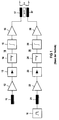
- first signal branch 10 first total current transformer 11 pulse currents and alternating currents for Further processing in a pulse current signal branch 10.
- an amplifier 12 a rectifier 13, an RC element 14, a switching stage 15 and a further amplifier 16 connected in series, from which the signal to a first Tripping coil 17 arrives.
- a second is quite appropriate Total current transformer 21 is present, corresponding to the first Signal branch 10 - in a direct current signal branch 20
- Amplifier 22, a rectifier diode 23, an RC element 24, a switching stage 25 and an amplifier 26 are connected downstream and from which the signal reaches a second trigger coil 27.
- the summation current transformer 21 is in the DC signal branch 20 driven by a clock generator 18, so that itself due to the inductive resistance of the secondary winding in the total current transformer 21 gives a signal. From the trip coils 17 or 27 is via a common actuating magnet controlled a key switch or the like.
- Figure 2 the two branches are on one Sum current transformer 11 connected, accordingly Figure 1 is a clock generator 18 is connected upstream.
- Essential is there that switching units 9, 19 and 29, which one Common clock generator 8 is assigned, alternately the blocking and release of the signals for the Pulse current signal branch 10 on the one hand and the direct current signal branch 20 on the other hand.
- the pulse current signal branch 10 is the feed of the Rectangle generator 18 on the second secondary winding of the Total current transformer 11 blocked.
- the supply of the square wave generator 9 on the second secondary winding of the summation current transformer and the signal transmission to the direct current signal branch 20 released.
- the frequency of the clock generator 8 is advantageously chosen with about 100 Hz, so that response times of 10 ms is possible.
- the frequency of the square wave generator 18 for the DC signal generator is at 0.5 to 3 kHz.
- FIG. 3 the system according to FIG. 2 is modified in such a way that that the same secondary winding of the summation current transformer 11 in time for the pulse current transformation and DC signaling is used.
- the processing company Signal branch with the switching elements 13 to 16 only available once. This is also only one trigger coil 17th necessary.
- FIGS. 4 and 5 Such systems are shown in FIGS. 4 and 5, in which the pulse current signal branch 10 and the direct current signal branch 20 are constructed essentially in accordance with FIGS. 2 and 3, but the amplifier 12 in the pulse current signal branch is preceded by a bandstopper 41 and the direct current signal branch is preceded by a bandpass filter 42.
- Band-stop filter 41 and band-pass filter 42 each work with the selective frequency f OSZ , the second secondary winding of the summation current converter 11 being controlled by an oscillator as a clock generator 18 with this frequency f OSZ .
- Figure 5 differs from Figure 4 in a corresponding manner like Figure 3 of Figure 2 in that the signal processing is carried out together in one signal branch and the pulse current signal branch 10 on the bandstop 41 and subsequent amplifier 12 and the DC signal branch 20 limited to the bandpass 42 and subsequent amplifier 22.
- the total current transformer 11 only needs a secondary winding and is still only a trip coil 17 available.
- the generator frequency f OSZ is preferably approximately 1 to 10 kHz.
- a sine generator 18 is specifically operated as a clock generator.
- the signal of the sine generator is superimposed with the transformed pulse currents of the sum current transformer 11.
- the signal of the sine generator is masked out by the band-stop filter 41 and only the signal of the transformed pulse currents is processed further.
- the signal of the sine generator is filtered out with the bandpass 42 and processed further for the direct current signal branch.
- a square wave generator 18 is used as a signal generator for the direct current signal branch 10 with the frequency f osz .
- the harmonics of the square wave generator 18, which pass the bandstop of the pulse signal branch 20, are calibrated as a constant in the subsequent amplifier. Further processing after the amplifiers then takes place in the common signal branch with the switching elements 13 to 17.
- a saturation converter 110 is present as a direct current sensor.
- the winding W1 consisting of the network circuit lines forms with the winding W2 a transformer for the pulse and AC residual currents, which processes in the pulse signal branch 10 will.
- the windings W3 and W4 form the saturation transformer.
- the clock generator 8 alternately Oscillator voltage and the amplified output signal of the saturation transformer on the one hand or the amplified output signal the pulse transmitter on the other hand. In order to becomes a mutual interference and influencing of the two Signal branches prevented.
- FIG 7 is the same arrangement using an oscillator sensor shown as a DC sensor.
- the windings W3 and W4 of the summation current transformer Resonant circuit inductances of the oscillator 18, its voltage by the DC error in frequency and the Amplitude is changed.
- the oscillator voltage is in the DC signal branch 10 processed.
- Through the clock generator 8 become the oscillator voltage or the amplified output signal of the pulse current transformer switched through alternately, which in turn eliminates the mutual interference becomes.
- FIGS. 8 and 9 The same applies to FIGS. 8 and 9, with a band-stop filter 41 on the one hand and a band-pass filter 42 on the other hand for the frequency f OSZ in each of the two figures corresponding to FIG.
- the bandstop in the pulse signal branch 10 prevents the signal branch from being influenced by the oscillator signal.
- the direct current signal branch 20 is protected by the bandpass 42 from being influenced by alternating and pulse fault currents. Otherwise, the procedure is essentially the same as in the other examples.
Landscapes
- Engineering & Computer Science (AREA)
- Power Engineering (AREA)
- Testing Of Short-Circuits, Discontinuities, Leakage, Or Incorrect Line Connections (AREA)
- Protection Of Transformers (AREA)
- Driving Mechanisms And Operating Circuits Of Arc-Extinguishing High-Tension Switches (AREA)
- Keying Circuit Devices (AREA)
Applications Claiming Priority (2)
| Application Number | Priority Date | Filing Date | Title |
|---|---|---|---|
| DE29705030U | 1997-03-19 | ||
| DE29705030U DE29705030U1 (de) | 1997-03-19 | 1997-03-19 | Fehlerstromschutzschalter für Allstrom |
Publications (2)
| Publication Number | Publication Date |
|---|---|
| EP0866536A2 true EP0866536A2 (fr) | 1998-09-23 |
| EP0866536A3 EP0866536A3 (fr) | 1998-12-09 |
Family
ID=8037760
Family Applications (1)
| Application Number | Title | Priority Date | Filing Date |
|---|---|---|---|
| EP98104716A Withdrawn EP0866536A3 (fr) | 1997-03-19 | 1998-03-16 | Disjoncteur à courant de défaut pour tous-courants |
Country Status (2)
| Country | Link |
|---|---|
| EP (1) | EP0866536A3 (fr) |
| DE (1) | DE29705030U1 (fr) |
Cited By (8)
| Publication number | Priority date | Publication date | Assignee | Title |
|---|---|---|---|---|
| EP1478068A1 (fr) | 2003-05-15 | 2004-11-17 | Siemens Aktiengesellschaft | Dispositif de protection sensible à tout courant de défaut |
| EP1478069A1 (fr) | 2003-05-15 | 2004-11-17 | Siemens Aktiengesellschaft | Dispositif de protection sensible à tout courant de défaut |
| EP1478070A1 (fr) | 2003-05-15 | 2004-11-17 | Siemens Aktiengesellschaft | Dispositif de protection sensible à tout courant de défaut |
| FR2862423A1 (fr) * | 2003-11-18 | 2005-05-20 | Schneider Electric Ind Sas | Dispositif et procede de protection differentielle et appareil electrique comportant un tel dispositif |
| WO2010063043A1 (fr) * | 2008-12-02 | 2010-06-10 | Moeller Gebäudeautomation GmbH | Disjoncteur différentiel |
| WO2012130846A1 (fr) * | 2011-04-01 | 2012-10-04 | Eaton Industries (Austria) Gmbh | Disjoncteur à courant de défaut |
| CN103337830A (zh) * | 2013-03-21 | 2013-10-02 | 刘圣平 | 一种防故障失效的安全漏电保护器 |
| DE102014217928A1 (de) | 2014-09-08 | 2016-03-10 | Robert Bosch Gmbh | Verfahren und Vorrichtung zum Erkennen eines Gleichstrom-Fehlerstroms |
Families Citing this family (8)
| Publication number | Priority date | Publication date | Assignee | Title |
|---|---|---|---|---|
| DE19943802A1 (de) * | 1999-09-13 | 2001-03-15 | Siemens Ag | Allstromsensitive Fehlerstrom-Schutzeinrichtung und Verfahren zur Erfassung eines Fehlerstroms |
| DE102008037830A1 (de) * | 2008-08-14 | 2010-02-25 | Siemens Aktiengesellschaft | Fehlerstromerfassungsgerät |
| US8908338B2 (en) * | 2009-06-03 | 2014-12-09 | Siemens Industry, Inc. | Methods and apparatus for multi-frequency ground fault circuit interrupt grounded neutral fault detection |
| DE102011107721B4 (de) | 2011-07-14 | 2014-02-13 | Ean Elektroschaltanlagen Gmbh | Verfahren und Vorrichtung zur Messung elektrischer Ströme mit Hilfe eines Stromwandlers |
| EP2936640A1 (fr) * | 2012-12-24 | 2015-10-28 | Razvojni Center eNem Novi Materiali d.o.o. | Dispositif électronique pour des disjoncteurs à courant résiduel de type b et ses dérivés |
| CN104659742B (zh) * | 2013-11-15 | 2018-04-17 | 西门子公司 | 一种剩余电流装置 |
| DE102014221658B4 (de) * | 2014-07-04 | 2016-12-15 | Siemens Aktiengesellschaft | Fehlerstromschutzvorrichtung mit rein netzspannungsabhängiger Erfassung |
| DE102014221720A1 (de) * | 2014-07-04 | 2016-01-07 | Siemens Aktiengesellschaft | Fehlerstromschutzvorrichtung mit netzspannungsabhängiger und netzspannungsunabhängiger Erfassung |
Family Cites Families (6)
| Publication number | Priority date | Publication date | Assignee | Title |
|---|---|---|---|---|
| JPS55127826A (en) * | 1979-03-26 | 1980-10-03 | Fuji Electric Co Ltd | Leakage breaker |
| DE3205429A1 (de) * | 1982-02-16 | 1983-08-25 | VEB Elektroschaltgeräte Dresden, 8030 Dresden | Fehlerstromausloeser fuer gleich-, impuls- und wechselfehlerstroeme |
| AT383906B (de) * | 1985-04-16 | 1987-09-10 | Cti Ges Zur Pruefung Elektrote | Fehlerstromschutzschalter fuer fehlerwechselund fehlergleichstroeme |
| DE3823098A1 (de) * | 1988-07-07 | 1990-01-11 | Siemens Ag | Einrichtung zum schutz vor fehlerstroemen |
| DE3823099C2 (de) * | 1988-07-07 | 1996-09-26 | Siemens Ag | Einrichtung zum Schutz vor Fehlerströmen |
| DE4439072C2 (de) * | 1994-11-02 | 1996-09-26 | Kopp Heinrich Ag | Schutzschalter für die Abschaltung von Fehlerströmen beliebiger Stromart |
-
1997
- 1997-03-19 DE DE29705030U patent/DE29705030U1/de not_active Expired - Lifetime
-
1998
- 1998-03-16 EP EP98104716A patent/EP0866536A3/fr not_active Withdrawn
Cited By (17)
| Publication number | Priority date | Publication date | Assignee | Title |
|---|---|---|---|---|
| EP1478069A1 (fr) | 2003-05-15 | 2004-11-17 | Siemens Aktiengesellschaft | Dispositif de protection sensible à tout courant de défaut |
| EP1478070A1 (fr) | 2003-05-15 | 2004-11-17 | Siemens Aktiengesellschaft | Dispositif de protection sensible à tout courant de défaut |
| CN100367593C (zh) * | 2003-05-15 | 2008-02-06 | 西门子公司 | 交直流敏感的故障电流保护装置 |
| CN100375359C (zh) * | 2003-05-15 | 2008-03-12 | 西门子公司 | 交直流敏感的故障电流保护装置 |
| EP1478068A1 (fr) | 2003-05-15 | 2004-11-17 | Siemens Aktiengesellschaft | Dispositif de protection sensible à tout courant de défaut |
| FR2862423A1 (fr) * | 2003-11-18 | 2005-05-20 | Schneider Electric Ind Sas | Dispositif et procede de protection differentielle et appareil electrique comportant un tel dispositif |
| EP1533880A1 (fr) * | 2003-11-18 | 2005-05-25 | Schneider Electric Industries SAS | Dispositif et procédé de protection différentielle et appareil électrique comportant un tel dispositif |
| US8315023B2 (en) | 2008-12-02 | 2012-11-20 | Moeller Gebäudeautomation GmbH | Residual-current circuit breaker |
| WO2010063043A1 (fr) * | 2008-12-02 | 2010-06-10 | Moeller Gebäudeautomation GmbH | Disjoncteur différentiel |
| WO2012130846A1 (fr) * | 2011-04-01 | 2012-10-04 | Eaton Industries (Austria) Gmbh | Disjoncteur à courant de défaut |
| CN103563200A (zh) * | 2011-04-01 | 2014-02-05 | 伊顿工业(奥地利)有限公司 | 漏电断路器 |
| US9136074B2 (en) | 2011-04-01 | 2015-09-15 | Eaton Industries (Austria) Gmbh | Residual-current circuit breaker |
| CN103563200B (zh) * | 2011-04-01 | 2016-05-25 | 伊顿工业(奥地利)有限公司 | 漏电断路器 |
| CN103337830A (zh) * | 2013-03-21 | 2013-10-02 | 刘圣平 | 一种防故障失效的安全漏电保护器 |
| CN103337830B (zh) * | 2013-03-21 | 2016-02-10 | 刘圣平 | 一种防故障失效的安全漏电保护器 |
| DE102014217928A1 (de) | 2014-09-08 | 2016-03-10 | Robert Bosch Gmbh | Verfahren und Vorrichtung zum Erkennen eines Gleichstrom-Fehlerstroms |
| US10640000B2 (en) | 2014-09-08 | 2020-05-05 | Robert Bosch Gmbh | Method and device for detecting a direct-current fault current |
Also Published As
| Publication number | Publication date |
|---|---|
| DE29705030U1 (de) | 1998-07-23 |
| EP0866536A3 (fr) | 1998-12-09 |
Similar Documents
| Publication | Publication Date | Title |
|---|---|---|
| EP0866536A2 (fr) | Disjoncteur à courant de défaut pour tous-courants | |
| DE69024975T2 (de) | Spektrumerfassung von lichtbögen und radiofrequenzen | |
| DE3856334T2 (de) | Gerät zur Bewertung des Isolationszustandes | |
| DE69414605T2 (de) | Differentialschutzeinrichtung für einen leistungstransformator | |
| EP0267500B1 (fr) | Méthode et dispositif pour localiser un défaut de terre dans un réseau électrique triphasé | |
| DE69412938T2 (de) | Erdschlussschalter | |
| EP3226013B1 (fr) | Capteur de courant différentiel | |
| WO2014206651A1 (fr) | Procédé et dispositif de détection d'arc électrique | |
| DE112005001167T5 (de) | Differenzstromdetektion | |
| EP1267467B1 (fr) | Dispositif pour la détection des courants différentiels | |
| EP0273255B1 (fr) | Interrupteur de protection à courant différentiel | |
| DE4428118C2 (de) | Erdschlußortung in elektrischen Netzen mit einer Erdschlußspule | |
| DE2502322C2 (de) | Erdschluß-Schutzeinrichtung | |
| DE2731453C3 (de) | Erdschlußdetektor | |
| EP1478070B1 (fr) | Dispositif de protection sensible à tout courant de défaut | |
| EP1478069B1 (fr) | Dispositif de protection sensible à tout courant de défaut | |
| DE3543985A1 (de) | Anordnung zum erfassen von fehlerstroemen | |
| DE4128961C1 (en) | Detecting short circuit to earth in pulse inverter - using square wave HF voltage source in evaluation circuit to operate protection circuit when toroidal transformer saturates | |
| DE3119925A1 (de) | Verfahren und geraet zur erdschluss-fernortung an starkstrom-freileitungen | |
| DE102008037830A1 (de) | Fehlerstromerfassungsgerät | |
| DE2124178B2 (de) | Schutzeinrichtung zum feststellen von erdschluss-leckstroemen | |
| DE4429310C2 (de) | Verfahren und Vorrichtung zur Ortung von Erdschlüssen in Drehstromnetzen | |
| DE950737C (de) | Staffelschutz zur selektiven Erdschlussabschaltung in induktiv geerdeten Hochspannungs-Maschennetzen | |
| DE763216C (de) | Gestellschlussschutzvorrichtung fuer Wechselstrommaschinen unter Anwendung einer Gleichstromverspannung | |
| DE10128311C2 (de) | Vorrichtung zum Erfassen von elektrischen Differenzströmen |
Legal Events
| Date | Code | Title | Description |
|---|---|---|---|
| PUAI | Public reference made under article 153(3) epc to a published international application that has entered the european phase |
Free format text: ORIGINAL CODE: 0009012 |
|
| AK | Designated contracting states |
Kind code of ref document: A2 Designated state(s): AT BE CH DE DK ES FI FR GB GR IE IT LI LU MC NL PT SE |
|
| AX | Request for extension of the european patent |
Free format text: AL;LT;LV;MK;RO;SI |
|
| PUAL | Search report despatched |
Free format text: ORIGINAL CODE: 0009013 |
|
| AK | Designated contracting states |
Kind code of ref document: A3 Designated state(s): AT BE CH DE DK ES FI FR GB GR IE IT LI LU MC NL PT SE |
|
| AX | Request for extension of the european patent |
Free format text: AL;LT;LV;MK;RO;SI |
|
| AKX | Designation fees paid | ||
| STAA | Information on the status of an ep patent application or granted ep patent |
Free format text: STATUS: THE APPLICATION IS DEEMED TO BE WITHDRAWN |
|
| 18D | Application deemed to be withdrawn |
Effective date: 19990610 |