EP0866568B1 - Procédé et dispositif de réception pour la détection des données - Google Patents
Procédé et dispositif de réception pour la détection des données Download PDFInfo
- Publication number
- EP0866568B1 EP0866568B1 EP19970104786 EP97104786A EP0866568B1 EP 0866568 B1 EP0866568 B1 EP 0866568B1 EP 19970104786 EP19970104786 EP 19970104786 EP 97104786 A EP97104786 A EP 97104786A EP 0866568 B1 EP0866568 B1 EP 0866568B1
- Authority
- EP
- European Patent Office
- Prior art keywords
- arrival
- impulse responses
- data
- channel impulse
- signals
- Prior art date
- Legal status (The legal status is an assumption and is not a legal conclusion. Google has not performed a legal analysis and makes no representation as to the accuracy of the status listed.)
- Expired - Lifetime
Links
- 238000000034 method Methods 0.000 title claims description 52
- 238000001514 detection method Methods 0.000 title claims description 29
- 230000004044 response Effects 0.000 claims description 54
- 230000036961 partial effect Effects 0.000 claims description 19
- 238000012549 training Methods 0.000 claims description 12
- 239000011159 matrix material Substances 0.000 claims description 9
- 230000008859 change Effects 0.000 claims description 4
- 230000008569 process Effects 0.000 claims description 4
- 238000001228 spectrum Methods 0.000 claims description 4
- 238000010295 mobile communication Methods 0.000 claims description 3
- 230000001629 suppression Effects 0.000 claims 1
- 230000005540 biological transmission Effects 0.000 description 11
- 230000001413 cellular effect Effects 0.000 description 6
- 238000007476 Maximum Likelihood Methods 0.000 description 5
- 238000010586 diagram Methods 0.000 description 5
- 230000002452 interceptive effect Effects 0.000 description 5
- 238000012935 Averaging Methods 0.000 description 4
- 238000004891 communication Methods 0.000 description 4
- 238000012545 processing Methods 0.000 description 3
- 230000005855 radiation Effects 0.000 description 3
- 238000011161 development Methods 0.000 description 2
- 230000018109 developmental process Effects 0.000 description 2
- 238000000926 separation method Methods 0.000 description 2
- 230000036962 time dependent Effects 0.000 description 2
- 230000008901 benefit Effects 0.000 description 1
- 239000000969 carrier Substances 0.000 description 1
- 238000006243 chemical reaction Methods 0.000 description 1
- 230000001427 coherent effect Effects 0.000 description 1
- 238000005034 decoration Methods 0.000 description 1
- 239000006185 dispersion Substances 0.000 description 1
- 238000005516 engineering process Methods 0.000 description 1
- 238000011156 evaluation Methods 0.000 description 1
- 230000006872 improvement Effects 0.000 description 1
- 238000012423 maintenance Methods 0.000 description 1
- 238000005070 sampling Methods 0.000 description 1
- 230000002123 temporal effect Effects 0.000 description 1
- 238000012546 transfer Methods 0.000 description 1
Images



Classifications
-
- H—ELECTRICITY
- H04—ELECTRIC COMMUNICATION TECHNIQUE
- H04L—TRANSMISSION OF DIGITAL INFORMATION, e.g. TELEGRAPHIC COMMUNICATION
- H04L25/00—Baseband systems
- H04L25/02—Details ; arrangements for supplying electrical power along data transmission lines
- H04L25/0202—Channel estimation
- H04L25/0204—Channel estimation of multiple channels
-
- H—ELECTRICITY
- H04—ELECTRIC COMMUNICATION TECHNIQUE
- H04B—TRANSMISSION
- H04B1/00—Details of transmission systems, not covered by a single one of groups H04B3/00 - H04B13/00; Details of transmission systems not characterised by the medium used for transmission
- H04B1/69—Spread spectrum techniques
- H04B1/707—Spread spectrum techniques using direct sequence modulation
- H04B1/7097—Interference-related aspects
- H04B1/7103—Interference-related aspects the interference being multiple access interference
- H04B1/7105—Joint detection techniques, e.g. linear detectors
-
- H—ELECTRICITY
- H04—ELECTRIC COMMUNICATION TECHNIQUE
- H04B—TRANSMISSION
- H04B7/00—Radio transmission systems, i.e. using radiation field
- H04B7/02—Diversity systems; Multi-antenna system, i.e. transmission or reception using multiple antennas
- H04B7/04—Diversity systems; Multi-antenna system, i.e. transmission or reception using multiple antennas using two or more spaced independent antennas
- H04B7/08—Diversity systems; Multi-antenna system, i.e. transmission or reception using multiple antennas using two or more spaced independent antennas at the receiving station
- H04B7/0837—Diversity systems; Multi-antenna system, i.e. transmission or reception using multiple antennas using two or more spaced independent antennas at the receiving station using pre-detection combining
- H04B7/0842—Weighted combining
- H04B7/0845—Weighted combining per branch equalization, e.g. by an FIR-filter or RAKE receiver per antenna branch
-
- H—ELECTRICITY
- H04—ELECTRIC COMMUNICATION TECHNIQUE
- H04L—TRANSMISSION OF DIGITAL INFORMATION, e.g. TELEGRAPHIC COMMUNICATION
- H04L1/00—Arrangements for detecting or preventing errors in the information received
- H04L1/02—Arrangements for detecting or preventing errors in the information received by diversity reception
- H04L1/06—Arrangements for detecting or preventing errors in the information received by diversity reception using space diversity
-
- H—ELECTRICITY
- H04—ELECTRIC COMMUNICATION TECHNIQUE
- H04L—TRANSMISSION OF DIGITAL INFORMATION, e.g. TELEGRAPHIC COMMUNICATION
- H04L25/00—Baseband systems
- H04L25/02—Details ; arrangements for supplying electrical power along data transmission lines
- H04L25/03—Shaping networks in transmitter or receiver, e.g. adaptive shaping networks
- H04L25/03006—Arrangements for removing intersymbol interference
- H04L2025/0335—Arrangements for removing intersymbol interference characterised by the type of transmission
- H04L2025/03426—Arrangements for removing intersymbol interference characterised by the type of transmission transmission using multiple-input and multiple-output channels
-
- H—ELECTRICITY
- H04—ELECTRIC COMMUNICATION TECHNIQUE
- H04L—TRANSMISSION OF DIGITAL INFORMATION, e.g. TELEGRAPHIC COMMUNICATION
- H04L25/00—Baseband systems
- H04L25/02—Details ; arrangements for supplying electrical power along data transmission lines
- H04L25/0202—Channel estimation
- H04L25/0224—Channel estimation using sounding signals
- H04L25/0228—Channel estimation using sounding signals with direct estimation from sounding signals
-
- H—ELECTRICITY
- H04—ELECTRIC COMMUNICATION TECHNIQUE
- H04L—TRANSMISSION OF DIGITAL INFORMATION, e.g. TELEGRAPHIC COMMUNICATION
- H04L25/00—Baseband systems
- H04L25/02—Details ; arrangements for supplying electrical power along data transmission lines
- H04L25/03—Shaping networks in transmitter or receiver, e.g. adaptive shaping networks
- H04L25/03006—Arrangements for removing intersymbol interference
- H04L25/03178—Arrangements involving sequence estimation techniques
- H04L25/03331—Arrangements for the joint estimation of multiple sequences
Definitions
- the invention relates to a method and a receiving device for detecting data from via a radio interface transmitted subscriber signals, for example for Base stations in cellular networks.
- K denotes the number of mobile stations supplied by a base station simultaneously in the same frequency channel.
- Ka denotes the number of reception sensors that are assigned to a reception device, for example the base station.
- K * Ka radio channels in the uplink between the K mobile stations and the Ka reception sensors of the base station.
- the impulse responses g (k) (ka) of the radio channels are determined in the signal processing on the receiver side and, with knowledge of the impulse responses g (k) (ka), the data detection is carried out without the knowledge of spatial relationships.
- the influence of interferers cannot be sufficiently suppressed by this method of detection.
- the invention is therefore based on the object, an improved Method and an improved receiving device to indicate data detection. This task is accomplished by the method with the features of claim 1 and the Receiving device with the features of claim 13 solved. Developments of the invention are the subclaims refer to.
- the method according to the invention takes into account knowledge of by the directional inhomogeneity of the wave propagation caused interdependencies between the different Channel impulse responses that are known in the art as independent of each other.
- Under directional inhomogeneity is understood to be that of a participant emitted waves due to the properties of terrestrial Radio channels, e.g. through reflection, scattering and diffraction generally not evenly from all directions, but - in the form of individual partial waves - from a number of different ones Arrive directions of arrival at the receiving location.
- the method according to the invention it is now possible to Knowledge of the inhomogeneity of the direction Wave propagation caused mutual dependencies of interference signals that refer to interference sources or the transmission signals from others not assigned to the base station under consideration Mobile stations go back, take advantage of.
- the number of directions of incidence for each of the K subscriber signals is different. Without restriction the general public is assumed below that this number is the same for all K subscriber signals and has the value Kd.
- a first method step the direction of incidence of at least one partial wave is determined.
- a (k) (ka) (kd) are complex evaluation factors for superimposing the directionally selective channel impulse responses h (k) (ka) to the non-directionally selective channel impulse responses g (k) (ka) .
- h directionally selective channel impulse responses
- g non-directionally selective channel impulse responses g (k) (ka) .
- knowledge of directions of incidence or correlation matrices of interfering partial waves can also be used, if necessary.
- the computing effort when estimating the parameters according to the inventive method can thus be reduced.
- This matrix G is given by the geometrical arrangement and the complex characteristics of the Ka reception sensors, by the transmitted training sequences and the Kd directions of incidence.
- the vector h contains the discrete-time baseband equivalent of the K * Kd directionally selective channel impulse responses h (K) (Kd) .
- n m denotes an unknown (L * Ka) column vector of a discrete-time interference signal.
- Equation (1) G and em are known from equation (1), so that the directionally selective Channel impulse responses h can be determined.
- A is an (M * Ka) x (N * K) matrix, where M is the number of discrete sampling times of the received signal and N is the number of data symbols transmitted per subscriber.
- n is in turn an unknown (M * Ka) column vector of a discrete-time interference signal.
- equation (3) A - by the K * Kd directions of incidence, the directionally selective channel impulse responses h, the geometric Arrangement and complex characteristics of the reception sensors and when using CDMA subscriber separation by the used participant code - and e known so that the data d can be detected.
- the method according to the invention enables an improvement the reception quality, as additional knowledge for the Data detection the relationship between non-directionally selective Channel impulse responses g and directional selective Channel impulse responses h is used. All not directional Channel impulse responses g of the individual Ka reception sensors can respond to the same directionally selective channel impulse h can be returned.
- the directions of incidence are not directionally selective Channel impulse responses g from K * Ka channels and out these non-directionally selective channel impulse responses g die Direction of incidence determined by at least one partial wave.
- the non-directional channel impulse responses g form a good basis for the directional estimate, since in the receiving device the training sequences of the subscriber signals are known and a more accurate estimate than with unknown, data still to be detected is possible.
- a further development of the method according to the invention provides before, to determine the directions of incidence of the partial waves to use high-resolution direction estimation methods.
- high-resolution direction estimation methods such as MUSIC (Multiple Signal Classification) or ESPRIT (Estimation of Signal Parameters via Rotational Invariance Techniques) procedures, use knowledge of complex radiation characteristics the reception sensors or certain geometrical ones Requirements for the arrangement of the reception sensors, to be accurate and with little signal processing effort make directional estimate.
- the direction-selective channel impulse responses h are advantageously determined using the Gauss-Markov estimation method, an estimate h and for the direction-selective channel impulse responses h from: can be calculated.
- This method corresponds to the maximum likelihood estimate of the directionally selective channel impulse responses h and can be implemented at low cost by recursively solving (4).
- the method relates to the detection of the data, advantageously a method of maximum likelihood estimation or the zero-forcing process or the MMSE (Minimum Mean Square Error) method is selected.
- the channel impulse responses may change the direction of incidence little.
- Averaging improves the Direction estimation because random errors are reduced.
- the averaging for one radio block or a variety of radio blocks be performed.
- the number of radio blocks for an averaging, i.e. the time interval can be set be, with changes in directions of incidence a change of the time interval.
- the channel conditions change fast, for example when accelerating the movement of a mobile station, then the directional estimate limited to a shorter time interval.
- relationships are between determining the directionally selective Channel impulse responses and data detection exploited.
- the K subscriber signals exist from data-carrying sections and training sequences, whereby from the training sequences of the K subscriber signals originating reception signals the directionally selective channel impulse responses be determined and the data from those of the received portions originating from the data-carrying sections become.
- Determining the directionally selective channel impulse responses and the data detection can be made from subscriber signals of a radio block. So that lies for the Data detection provides a channel estimate that is as current as possible.
- determining the directionally selective Channel impulse responses and data detection from subscriber signals different radio blocks. This can be used for parallel processing, for example Channel estimation and data detection can be initiated or the This can reduce the computing effort for channel estimation be that the latter are repeated only at larger intervals becomes.
- the directions of incidence and / or the directionally selective Channel impulse responses using a tracking method a period longer than a radio frame related frame structure is determined again or there may be information about the directions of incidence and / or the directionally selective Channel impulse responses in the receiving device be saved permanently, if not or not at all are time-dependent.
- An update of this information about the directions of incidence, the directionally selective channel impulse responses and / or interferers can advantageously be arranged by an operations and maintenance center.
- the mobile communication system shown in FIG. 1 corresponds in its structure a well-known GSM cellular network, which consists of a multitude of mobile switching centers MSC, who are networked with each other or have access to establish a fixed network PSTN. Furthermore, these are mobile switching centers MSC with at least one base station controller each Connected to BSC. Any base station controller BSC in turn enables a connection to at least a base station BS.
- a base station is BS a radio station that uses a radio interface to establish a communication link to build mobile stations MS.
- FIG 1 are exemplary three radio connections between three Mobile stations MS and a base station BS shown.
- On Operations and maintenance center OMC realizes control and Maintenance functions for the cellular network or for parts thereof. This structure is transferable to other cellular networks, in which the invention can be used.
- the communication links between the base station BS and the mobile stations MS is subject to multipath propagation, by reflections on buildings, for example or plantings in addition to the direct propagation path are caused. If you assume a movement of the mobile stations MS then the multipath propagation together with other disturbances that the receiving Base station BS the signal components of the different Propagation paths of a subscriber signal are time-dependent overlap. It is also assumed that the Subscriber signals from different mobile stations MS at the receiving location superimposed on a reception signal e, em. task the receiving base station BS is in the subscriber signals to transmit transmitted data d and individual assign subscriber-specific communication connections.
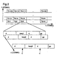
- the radio interface has it a frequency division multiplex (FDMA), a time division multiplex (TDMA) and a code division multiplex (CDMA) component.
- FDMA frequency division multiplex
- TDMA time division multiplex
- CDMA code division multiplex
- Multiple frequency bands along the frequency axis f are for the cellular network intended.
- the time axis t is such a Time grid consisting of several time slots per time frame divides that transmission into radio blocks he follows.
- the subscriber signals of several mobile stations MS are assigned to a group of participants Tln1, Tln2 .. Tln120, i.e. during the radio block of a group of participants, for example Tln3 for the three mobile stations MS of FIG 1, the subscriber signals overlap to form a received signal e, em by a receiving device in the base station BS is to be evaluated.
- a subscriber signal Within a radio block, a subscriber signal consists of two data-carrying sections with data d, in the middle of which a subscriber-specific training sequence tseq1 to tseqK is introduced.
- the radio block is completed by a protection time gp.
- FIG. 3 shows a receiving device with assigned receiving sensors A shown.
- This receiving device is Part of the base station BS and receives from the sending mobile stations MS of the cellular network receive signals e, em. in the the reception case for base station BS is also shown, nevertheless, there is usually a two-sided one Communication link, i.e. the base station BS also has a transmitter.
- the receiving device comprises several channel estimators JCE, several DOAE direction estimators, one directionally selective Channel estimator JDCE and a detection device JDD. additionally to the received signals e, em lies in the receiving device a priori information about the number K of the Participants whose training sequences tseq1, .., tseqK and their Participant code c before, if necessary, can also about information Interference signals are available.
- the channel estimators JCE receive the - already digitized - receive signals em from the receive sensors A.
- the channel estimators JCE determine the non-directionally selective channel impulse responses g by means of a Gauss-Markov or a maximum likelihood estimate.
- the reception signal of a reception sensor A is evaluated for each channel estimator JCE, K non-directionally selective channel impulse responses g being provided at the outputs of the channel estimators JCE.
- the non-directionally selective channel impulse responses g each fed to the K direction estimators DOAE, which are participant-related a directional estimate based on these Carry out directionally selective channel impulse responses g.
- the number of directions of incidence determined per subscriber signal is called Kd. This number Kd can vary Distinguish subscriber signal to subscriber signal.
- DOA Direction Of Arrival comes the one- or multi-dimensional UNITARY-ESPRIT algorithm used.
- the reception signals em (ka) of the reception sensors A originating from the training sequences tseq1 to tseqK, and the determined directions of incidence DOA of the partial waves are processed and directionally selective channel impulse responses h are determined therefrom.
- This channel estimation is based on the maximum likelihood estimation method.
- the Ka received signals e (ka) , ka 1..Ka
- the determined directionally selective channel impulse responses h and the determined directions of incidence DOA are fed to the detection device JDD, which also contains the subscriber codes c and additional knowledge a-priori-info about the direction of incidence of interference signals processed in the form of R n or the geographical position of mobile stations MS with respect to the base station BS.
- the detection of the data d takes place in this detection device JDD on the basis of the received signals e (ka) , which originate from the data-carrying sections. A zero-forcing process is used for this. Alternative advantageous methods are maximum likelihood estimation or an MMSE method.
- the detected data d of the K subscriber signals for a radio block are applied to outputs of the detection device JDD.
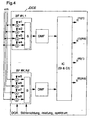
- a directionally selective channel estimator JDCE which contains beamformers BF, each of which is weighted for the Ka received signals em (ka) by weighting factors w1 to w4 or w5 to w8, which are individual to the beamformer, and a summation of the signal components in a summing device S to form a signal the signal-to-noise ratio is maximized, which signal is then fed to a decorrelating signal-matched filter DMF.
- the intrinsic SI and cross interferences CI are compensated and directionally selective channel impulse responses h are obtained.
- the information is also shown in the beam formers BF about the directions of incidence DOA of the partial waves and the directions and relative powers of the disturbing partial waves processed. These directions influence the weighting factors w1 to w4 or w5 to w8 for each beamformer BF individually.
- the BF beamformers and the decorrelating ones matched filter DMF act like a spatially resolving decorrelating signal-adapted filter, the each applied to a partial wave - thus K * Kd.
- This Detection device JDD processes the data carriers Sections of the received signals e, corresponding to the described procedure for the directionally selective channel estimator JDCE is a spatially dissolving decoration matched filter the K * Kd partial waves of the received signals e to maximize the signal-to-noise ratio superimposed.
- This maximizing the signal-to-noise ratio is DOA of each subscriber signal for each direction of incidence performed, the Kd signal components of each Partial waves of a subscriber signal using the maximum ratio combining method in summing devices S1 to SK be overlaid.
- the subscriber signals are then fed to a device IC for interference cancellation, which compensates for the intersymbol ISI and multiple access (MAI) interferences.
- the information about the subscriber codes c, the directions of incidence DOA, the directionally selective channel impulse responses h and possibly prior knowledge about the interferers are also processed in the form of R n .
- the detected data d of the subscriber signals are present separately at an output of the device IC for interference cancellation.
- a so-called JD (Joint Detection) procedure is used for interference cancellation.
- the temporal Dispersion and variance of the received signals reduced. Furthermore, the spatial resolution allows a larger one Number of mobile stations MS in a radio area Base station BS can be supplied or the radio area can be designed by the directivity in such a way that the Transmission power of the mobile stations MS significantly reduced become.
Landscapes
- Engineering & Computer Science (AREA)
- Computer Networks & Wireless Communication (AREA)
- Signal Processing (AREA)
- Power Engineering (AREA)
- Mobile Radio Communication Systems (AREA)
Claims (20)
- Procédé pour la détection de données (d) à partir de signaux d'abonnés transmis par une interface radio, dans lequelun nombre Ka de capteurs de réception (A) est attribué à un dispositif de réception,un k-ième signal d'abonnés, k = 1 .. K, est transmis par Kd ondes partielles qui se différencient dans leur direction d'incidence (DOA) sur le lieu de réception,la direction d'incidence (DOA) est déterminée par au moins une onde partielle,des réponses d'impulsion de canal (h(k)(kd)) sélectives en direction, c'est-à-dire pouvant être attribuées à différentes directions d'incidence (DOA), sont déterminées, etles données (d(k)) sont détectées à partir des signaux de réception (e (ka)) provenant de K signaux d'abonnés en utilisant les directions d'incidence (DOA) déterminées auparavant et les réponses d'impulsion de canal (h(k)(kd)) sélectives en direction.
- Procédé selon la revendication 1, dans lequelles K signaux d'abonnés se composent de parties supportant des données et de séquences d'entraínement (tseq1, tseq2, tseqK),les réponses d'impulsion de canal (h (k) (kd)) sélectives en direction sont déterminées à partir des signaux de réception (em(ka)) provenant des séquences d'entraínement (tseq1, tseq2, tseqK) des K signaux d'abonnés, etles données (d(k)) sont détectées à partir des signaux de réception (e(ka)) provenant des parties supportant des données.
- Procédé selon la revendication 1 ou 2, dans lequel
la détermination des réponses d'impulsion de canal (h(k)(kd)) sélectives en direction et la détection de données sont effectuées à partir de signaux d'abonnés d'un bloc radio. - Procédé selon la revendication 1 ou 2, dans lequel
la détermination des réponses d'impulsion de canal (h(k)(kd)) sélectives en direction et la détection de données sont effectuées à partir de signaux d'abonnés de différents blocs radio. - Procédé selon la revendication 4, dans lequel
les directions d'incidence (DOA) et/ou les réponses d'impulsion de canal (h(k)(kd)) sélectives en direction sont déterminées de nouveau avec une procédure d'asservissement selon une période qui est plus longue qu'une structure de cadre spécifique au bloc radio. - Procédé selon la revendication 4, dans lequel
des informations (info a priori) sur les directions d'incidence (DOA) et/ou sur les réponses d'impulsion de canal (h(k)(kd)) sélectives en direction sont mémorisées de façon permanente dans le dispositif de réception. - Procédé selon la revendication 6, dans lequel
les informations (info a priori) sur les directions d'incidence (DOA), les réponses d'impulsion de canal (h(k)(kd)) sélectives en direction et/ou sur des sources parasites peuvent être réglées par un centre opérationnel et de maintenance (OMC). - Procédé selon l'une quelconque des revendications précédentes, pour lequel, pour la détermination des directions d'incidence (DOA),des réponses d'impulsion de canal (g) non sélectives en direction sont déterminées, etla direction d'incidence (DOA) d'au moins une onde partielle est déterminée à partir des réponses d'impulsion du canal (g) non sélectives en direction.
- Procédé selon l'une quelconque des revendications précédentes, dans
lequel des procédés d'estimation de direction à haute résolution sont utilisés pour la détermination des directions d'incidence (DOA) des ondes partielles. - Procédé selon l'une quelconque des revendications précédentes, dans
lequel des méthodes pour la réaction de décision sont appliquées pour la détection des données (d). - Procédé selon l'une quelconque des revendications précédentes, dans
lequel on effectue un calcul de moyenne des valeurs déterminées par rapport à un intervalle de temps pour la détermination des directions d'incidence (DOA). - Procédé selon la revendication 11, dans lequel
l'intervalle de temps peut être réglé, des variations des directions d'incidence (DOA) provoquant une variation de l'intervalle de temps. - Dispositif de réception pour la détection des données (d) à partir de
signaux d'abonnés transmis au moyen d'une interface radio, moyennant quoi un k-ième signal d'abonné, k = 1 .. K, est transmis par Kd ondes partielles qui se différencient dans leur direction d'incidence (DOA) sur le lieu de réception,avec Ka capteurs de réception (A) attribués,avec au moins un estimateur de direction (DOAE) pour la détermination de directions d'incidence (DOA) d'au moins une onde partielle,avec un estimateur de canal (JDCE) sélectif en direction pour la détermination de réponses d'impulsion de canal (h(k)(kd)) sélectives en direction, c'est-à-dire pouvant être attribuées à différentes directions d'incidence (DOA),avec un dispositif de détection (JDD) pour la détection des données (d) de signaux de réception (e(ka)) provenant de parties supportant des données des K signaux d'abonnés, en utilisant les directions d'incidence (DOA) déterminées auparavant et les réponses d'impulsion de canal (h(k)(kd)) sélectives en direction. - Dispositif de réception selon la revendication 13,
avec au moins un estimateur de canal (JCE) pour l'estimation de réponses d'impulsion de canal (g) non sélectives en direction. - Dispositif de réception selon la revendication 13 ou 14,
dans lequel un procédé AMRC est utilisé pour une séparation d'abonnés et le dispositif de détection (JDD) effectue la détection de données à l'aide de codes (c) spécifiques à chaque abonné. - Dispositif de réception selon la revendication 15,
dans lequel le dispositif de détection (JDD) tient compte des influences des autres signaux d'abonnés pour la détection des données. - Dispositif de réception selon l'une quelconque des revendications 13 à 16,
dans lequel une séparation d'abonnés est utilisée selon une procédure AMRT et/ou une procédure AMRF. - Dispositif de réception selon l'une quelconque des revendications 13 à 17, dans lequel le dispositif de détection (JDD) effectue une suppression des interférences en utilisant la connaissance sur les directions d'incidence, les puissances, le spectre ou une matrice de corrélation de signaux parasites.
- Dispositif de réception selon l'une quelconque des revendications 13 à 18, dans lequel le dispositif de détection (JDD) effectue une estimation de canal améliorée et une suppression des interférences d'après l'estimation des directions d'incidence (DOA) de signaux parasites dans le sens d'une itération.
- Dispositif de réception selon l'une quelconque des revendications 13 à 19, qui est conçu comme une partie d'une station de base (BS) d'un système de communication mobile.
Priority Applications (3)
| Application Number | Priority Date | Filing Date | Title |
|---|---|---|---|
| DE59711749T DE59711749D1 (de) | 1997-03-20 | 1997-03-20 | Verfahren und Empfangseinrichtung zum Detektieren von Daten |
| ES97104786T ES2224192T3 (es) | 1997-03-20 | 1997-03-20 | Procedimiento y equipo receptor para detectar datos. |
| EP19970104786 EP0866568B1 (fr) | 1997-03-20 | 1997-03-20 | Procédé et dispositif de réception pour la détection des données |
Applications Claiming Priority (1)
| Application Number | Priority Date | Filing Date | Title |
|---|---|---|---|
| EP19970104786 EP0866568B1 (fr) | 1997-03-20 | 1997-03-20 | Procédé et dispositif de réception pour la détection des données |
Publications (2)
| Publication Number | Publication Date |
|---|---|
| EP0866568A1 EP0866568A1 (fr) | 1998-09-23 |
| EP0866568B1 true EP0866568B1 (fr) | 2004-06-30 |
Family
ID=8226625
Family Applications (1)
| Application Number | Title | Priority Date | Filing Date |
|---|---|---|---|
| EP19970104786 Expired - Lifetime EP0866568B1 (fr) | 1997-03-20 | 1997-03-20 | Procédé et dispositif de réception pour la détection des données |
Country Status (3)
| Country | Link |
|---|---|
| EP (1) | EP0866568B1 (fr) |
| DE (1) | DE59711749D1 (fr) |
| ES (1) | ES2224192T3 (fr) |
Families Citing this family (8)
| Publication number | Priority date | Publication date | Assignee | Title |
|---|---|---|---|---|
| DE19916912A1 (de) * | 1999-04-14 | 2000-11-09 | Siemens Ag | Strahlformungsverfahren der Abwärtsstrecke für Basisstationen in Funk-Kommunikationssystemen |
| DE19923407C1 (de) * | 1999-05-21 | 2000-08-24 | Siemens Ag | Empfangsverfahren und Empfangseinrichtung für Mobilfunkanwendungen |
| EP1128575B1 (fr) * | 2000-02-22 | 2006-04-26 | Telefonaktiebolaget LM Ericsson (publ) | Evaluation de canal dans un récepteur en diversité utilisant des séquences d'apprentisssage simultanément transmises |
| DE10025287B4 (de) | 2000-05-22 | 2006-06-08 | Siemens Ag | Verfahren und Kommunikationssystem zur Schätzung einer Störungs-Kovarianzmatrix für die Abwärtsverbindung in zellularen Mobilfunknetzen mit adaptiven Antennen |
| US6907270B1 (en) * | 2000-10-23 | 2005-06-14 | Qualcomm Inc. | Method and apparatus for reduced rank channel estimation in a communications system |
| FR2829241B1 (fr) * | 2001-09-05 | 2006-07-21 | Thales Sa | Procede et dispositif de radiogoniometrie cooperative en transmission |
| US7724851B2 (en) * | 2004-03-04 | 2010-05-25 | Bae Systems Information And Electronic Systems Integration Inc. | Receiver with multiple collectors in a multiple user detection system |
| CN103607219B (zh) * | 2013-11-07 | 2016-02-03 | 电子科技大学 | 一种电力线通信系统的噪声预测方法 |
Family Cites Families (2)
| Publication number | Priority date | Publication date | Assignee | Title |
|---|---|---|---|---|
| US5515378A (en) * | 1991-12-12 | 1996-05-07 | Arraycomm, Inc. | Spatial division multiple access wireless communication systems |
| TW351886B (en) * | 1993-09-27 | 1999-02-01 | Ericsson Telefon Ab L M | Using two classes of channels with different capacity |
-
1997
- 1997-03-20 EP EP19970104786 patent/EP0866568B1/fr not_active Expired - Lifetime
- 1997-03-20 DE DE59711749T patent/DE59711749D1/de not_active Expired - Fee Related
- 1997-03-20 ES ES97104786T patent/ES2224192T3/es not_active Expired - Lifetime
Also Published As
| Publication number | Publication date |
|---|---|
| DE59711749D1 (de) | 2004-08-05 |
| ES2224192T3 (es) | 2005-03-01 |
| EP0866568A1 (fr) | 1998-09-23 |
Similar Documents
| Publication | Publication Date | Title |
|---|---|---|
| DE69604595T2 (de) | Verfahren und anordnung zur räumlichen multiplexierung/demultiplexierung von funksignalen in einem sdma-mobilfunksystem | |
| DE69434616T2 (de) | Mehrwegeempfang unter Verwendung von Matrizenberechnungen und adaptiver Strahlbildung | |
| DE69521050T2 (de) | Verfahren und vorrichtung zur interferenzunterdrückung in einem digitalen zellularen mehrfachantennenkommunikationssystem | |
| EP1013003B1 (fr) | Procede d'evaluation de canal a partir de signaux de reception transmis via un canal radio | |
| DE60110039T2 (de) | Lineare signaltrennung durch polarisations-diversität | |
| DE69727476T2 (de) | Verfahren und vorrichtung zur interferenzunterdrückung mit verschiedenen strahlen, polarisationen und phasenreferenzen | |
| DE60128874T2 (de) | Spread-spektrum-empfänger | |
| DE69233707T2 (de) | Schnurloses Kommunikationssystem mit Vielfachzugriff durch Raummultiplexierung | |
| EP1166393B1 (fr) | Procede et dispositif de mise en forme de faisceau | |
| DE69329893T2 (de) | Verfahren und Einrichtung zur Kompensation von Mehrwegeschwund und von Gleichwellenstörungen in einem Funksignal | |
| DE19511751C2 (de) | Verfahren zur Rekonstruktion von durch Mehrwegeausbreitung gestörten Signalen | |
| DE19803188B4 (de) | Verfahren und Basisstation zur Datenübertragung in einem Funk-Kommunikationssystem | |
| DE69803454T2 (de) | Verfahren zur funkpeilung und zusammenwirkendes übertragungsgerät | |
| DE102011004257B4 (de) | Vorrichtung und Verfahren zum Antennendiversitätsempfang | |
| EP0899896A1 (fr) | Procédé et dispositif d'estimation de paramètres spatiaux de canaux de transmission | |
| EP0970388B1 (fr) | Procede d'evaluation de la direction | |
| DE19741872C1 (de) | Adaptiver Empfänger für CDMA Basisstationen | |
| DE102011004259B4 (de) | Vorrichtung und Verfahren zum Antennendiversitätsempfang | |
| AT407933B (de) | Verfahren zur trennung und zur detektion von gleichkanal-signalen | |
| EP1224749B1 (fr) | Formation d'un faisceau dans un systeme de communication radio | |
| EP0866568A1 (fr) | Procédé et dispositif de réception pour la détection des données | |
| US6225948B1 (en) | Method for direction estimation | |
| DE10350362B4 (de) | Verfahren zum Vorhersagen eines Kanalkoeffizienten | |
| DE69732335T2 (de) | Sende-Kalibrierverfahren für eine mit einer Mehrelementantenne ausgestattete Basisstation | |
| DE10026076C2 (de) | Verfahren und Vorrichtung zum Auswerten eines Uplink-Funksignals |
Legal Events
| Date | Code | Title | Description |
|---|---|---|---|
| PUAI | Public reference made under article 153(3) epc to a published international application that has entered the european phase |
Free format text: ORIGINAL CODE: 0009012 |
|
| AK | Designated contracting states |
Kind code of ref document: A1 Designated state(s): DE ES FR GB IT |
|
| 17P | Request for examination filed |
Effective date: 19990205 |
|
| AKX | Designation fees paid |
Free format text: DE ES FR GB IT |
|
| RBV | Designated contracting states (corrected) |
Designated state(s): DE ES FR GB IT |
|
| GRAP | Despatch of communication of intention to grant a patent |
Free format text: ORIGINAL CODE: EPIDOSNIGR1 |
|
| GRAS | Grant fee paid |
Free format text: ORIGINAL CODE: EPIDOSNIGR3 |
|
| GRAA | (expected) grant |
Free format text: ORIGINAL CODE: 0009210 |
|
| AK | Designated contracting states |
Kind code of ref document: B1 Designated state(s): DE ES FR GB IT |
|
| REG | Reference to a national code |
Ref country code: GB Ref legal event code: FG4D Free format text: NOT ENGLISH |
|
| GBT | Gb: translation of ep patent filed (gb section 77(6)(a)/1977) |
Effective date: 20040630 |
|
| REF | Corresponds to: |
Ref document number: 59711749 Country of ref document: DE Date of ref document: 20040805 Kind code of ref document: P |
|
| REG | Reference to a national code |
Ref country code: ES Ref legal event code: FG2A Ref document number: 2224192 Country of ref document: ES Kind code of ref document: T3 |
|
| ET | Fr: translation filed | ||
| PLBE | No opposition filed within time limit |
Free format text: ORIGINAL CODE: 0009261 |
|
| STAA | Information on the status of an ep patent application or granted ep patent |
Free format text: STATUS: NO OPPOSITION FILED WITHIN TIME LIMIT |
|
| 26N | No opposition filed |
Effective date: 20050331 |
|
| PGFP | Annual fee paid to national office [announced via postgrant information from national office to epo] |
Ref country code: ES Payment date: 20070329 Year of fee payment: 11 |
|
| PGFP | Annual fee paid to national office [announced via postgrant information from national office to epo] |
Ref country code: DE Payment date: 20070331 Year of fee payment: 11 |
|
| PGFP | Annual fee paid to national office [announced via postgrant information from national office to epo] |
Ref country code: IT Payment date: 20070625 Year of fee payment: 11 |
|
| REG | Reference to a national code |
Ref country code: GB Ref legal event code: 732E |
|
| PGFP | Annual fee paid to national office [announced via postgrant information from national office to epo] |
Ref country code: FR Payment date: 20070319 Year of fee payment: 11 |
|
| REG | Reference to a national code |
Ref country code: FR Ref legal event code: ST Effective date: 20081125 |
|
| PG25 | Lapsed in a contracting state [announced via postgrant information from national office to epo] |
Ref country code: DE Free format text: LAPSE BECAUSE OF NON-PAYMENT OF DUE FEES Effective date: 20081001 |
|
| PG25 | Lapsed in a contracting state [announced via postgrant information from national office to epo] |
Ref country code: FR Free format text: LAPSE BECAUSE OF NON-PAYMENT OF DUE FEES Effective date: 20080331 |
|
| REG | Reference to a national code |
Ref country code: ES Ref legal event code: FD2A Effective date: 20080322 |
|
| PG25 | Lapsed in a contracting state [announced via postgrant information from national office to epo] |
Ref country code: ES Free format text: LAPSE BECAUSE OF NON-PAYMENT OF DUE FEES Effective date: 20080322 |
|
| PG25 | Lapsed in a contracting state [announced via postgrant information from national office to epo] |
Ref country code: IT Free format text: LAPSE BECAUSE OF NON-PAYMENT OF DUE FEES Effective date: 20080320 |
|
| PGFP | Annual fee paid to national office [announced via postgrant information from national office to epo] |
Ref country code: GB Payment date: 20150319 Year of fee payment: 19 |
|
| GBPC | Gb: european patent ceased through non-payment of renewal fee |
Effective date: 20160320 |
|
| PG25 | Lapsed in a contracting state [announced via postgrant information from national office to epo] |
Ref country code: GB Free format text: LAPSE BECAUSE OF NON-PAYMENT OF DUE FEES Effective date: 20160320 |