EP0866638B1 - Amplificateur audiovisuel - Google Patents
Amplificateur audiovisuel Download PDFInfo
- Publication number
- EP0866638B1 EP0866638B1 EP98104167A EP98104167A EP0866638B1 EP 0866638 B1 EP0866638 B1 EP 0866638B1 EP 98104167 A EP98104167 A EP 98104167A EP 98104167 A EP98104167 A EP 98104167A EP 0866638 B1 EP0866638 B1 EP 0866638B1
- Authority
- EP
- European Patent Office
- Prior art keywords
- channel
- amplifier
- signal
- amplifiers
- wiring
- Prior art date
- Legal status (The legal status is an assumption and is not a legal conclusion. Google has not performed a legal analysis and makes no representation as to the accuracy of the status listed.)
- Expired - Lifetime
Links
Images







Classifications
-
- H—ELECTRICITY
- H03—ELECTRONIC CIRCUITRY
- H03F—AMPLIFIERS
- H03F3/00—Amplifiers with only discharge tubes or only semiconductor devices as amplifying elements
- H03F3/68—Combinations of amplifiers, e.g. multi-channel amplifiers for stereophonics
-
- H—ELECTRICITY
- H04—ELECTRIC COMMUNICATION TECHNIQUE
- H04R—LOUDSPEAKERS, MICROPHONES, GRAMOPHONE PICK-UPS OR LIKE ACOUSTIC ELECTROMECHANICAL TRANSDUCERS; ELECTRIC HEARING AIDS; PUBLIC ADDRESS SYSTEMS
- H04R5/00—Stereophonic arrangements
- H04R5/04—Circuit arrangements, e.g. for selective connection of amplifier inputs/outputs to loudspeakers, for loudspeaker detection, or for adaptation of settings to personal preferences or hearing impairments
-
- H—ELECTRICITY
- H03—ELECTRONIC CIRCUITRY
- H03F—AMPLIFIERS
- H03F2200/00—Indexing scheme relating to amplifiers
- H03F2200/03—Indexing scheme relating to amplifiers the amplifier being designed for audio applications
-
- H—ELECTRICITY
- H03—ELECTRONIC CIRCUITRY
- H03F—AMPLIFIERS
- H03F2200/00—Indexing scheme relating to amplifiers
- H03F2200/321—Use of a microprocessor in an amplifier circuit or its control circuit
-
- H—ELECTRICITY
- H04—ELECTRIC COMMUNICATION TECHNIQUE
- H04R—LOUDSPEAKERS, MICROPHONES, GRAMOPHONE PICK-UPS OR LIKE ACOUSTIC ELECTROMECHANICAL TRANSDUCERS; ELECTRIC HEARING AIDS; PUBLIC ADDRESS SYSTEMS
- H04R2420/00—Details of connection covered by H04R, not provided for in its groups
- H04R2420/03—Connection circuits to selectively connect loudspeakers or headphones to amplifiers
-
- H—ELECTRICITY
- H04—ELECTRIC COMMUNICATION TECHNIQUE
- H04S—STEREOPHONIC SYSTEMS
- H04S3/00—Systems employing more than two channels, e.g. quadraphonic
Definitions
- the present invention relates to AV amplifiers, and more particularly, to an AV amplifier capable of selectively switching between a multichannel reproducing mode and a two-channel stereo reproducing mode.
- AV amplifier which performs multichannel reproduction of images and sounds rapidly becomes widespread due to penetration of home theaters.
- This kind of AV amplifier performs the multichannel reproduction by decoding audio information (which is multichannel audio information encoded as two-channel audio information) obtained from various sources (a DVD, digital broadcast and so forth).
- audio information which is multichannel audio information encoded as two-channel audio information
- sources a DVD, digital broadcast and so forth.
- a bi-wiring speaker demands for stereo reproduction with a single high-class speaker compatible with bi-amp and bi-wiring (hereinafter referred to as a bi-wiring speaker), in which sound quality is valued, are still great. It is a great burden in terms of price and space to buy and set an amplifier for a home theater and an amplifier for stereo reproduction separately. Therefore, it is requested to use one AV amplifiers to perform multichannel reproduction and also drive bi-wiring speakers in stereo.
- Fig. 14 is a block diagram showing a state in which the bi-wiring speakers are connected to the conventional AV amplifier.
- two-channel signals in which multichannel (here, four-channel) information is encoded
- a source which is not shown in the figure (a DVD, digital broadcast and so forth) are inputted from input terminals 1 L and 1 R and decoded as original four-channel signals by a decoder 2.
- a signal 3L for a L channel outputted from the decoder 2 is amplified by an amplifiers 4A for the L channel and then inputted to a terminal HF for high-frequency and a terminal LF for low-frequency of a bi-wiring speaker 6L for the L channel in parallel.
- a signal 3R for a R channel outputted from the decoder 2 is amplified by an amplifier 4C for the R channel and then inputted to a terminal HF for high-frequency and a terminal LF for low-frequency of a bi-wiring speaker 6R for the R channel in parallel.
- a signal 3C for a C channel (a center channel) outputted from the decoder 2 is amplified by an amplifier 4B for the C channel and then inputted to a center speaker 11.
- a signal 3S for a S channel (a surround channel) outputted from the decoder 2 is amplified by an amplifier 4D for the S channel and then inputted to a surround speaker 12.
- the conventional AV amplifier has a problem that in the case where the bi-wiring speakers 6L and 6R are driven in a two-channel stereo reproducing mode with using the conventional AV amplifier as described in the above, only two amplifiers which are the amplifier 4A for the L channel and the amplifier 4C for the R channel are used as an amplifying circuit, therefore the bi-wiring speaker is substantially used in a normal mode in which the terminals HF for high-frequency and the terminals LF for low-frequency are short circuited as shown in Fig. 14 , thereby high-quality sound reproduction with the bi-wiring connection can not be realized.
- a power amplifier device comprised of at least two amplifying circuits, each including an input, at least one voltage amplifier stage, at least one power amplifier stage adapted for signal impedance conversion, and an output, all connected in series, and further including a signal input terminal and a signal output terminal.
- Plural switch means are provided for selectively interconnecting the voltage amplifier stages and the power amplifier stages of the amplifying circuits for selectively establishing a parallel connected amplifying circuit, individual amplifying circuits and a balanced transformerless connection across the signal output terminals.
- an object of the present invention is to provide an AV amplifier capable of performing multichannel reproduction and driving a bi-wiring speaker with high-quality sound using bi-wiring connection at a two-channel stereo reproducing time as well.
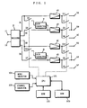
- Fig. 1 is a block diagram showing a structure of an AV amplifiers according to a first embodiment of the present invention.
- two-channel signals in which multichannel (here, four-channel) information is encoded
- a source which is not shown in the figure (a DVD, digital broadcast and so forth)
- a signal 3L for a L channel outputted from the decoder 2 is amplified by an amplifiers 4A for the L channel to be given to an output terminal 5A through a switch S11 and given to an output terminal 5B through a switch S1 as well.
- a signal 3C for a C channel (a center channel) outputted from the decoder 2 is amplified by an amplifier 4B for the C channel through a switch S2 to be given to the output terminal 5B through a switch S3 and given to an output terminal 5C through a switch S4 as well.
- a signal 3R for a R channel outputted from the decoder 2 is amplified by an amplifiers 4C for the R channel to be given to an output terminal 5D through a switch S12 and given to an output terminal 5E through a switch S6 as well.
- a signal 3S for a S channel (a surround channel) outputted from the decoder 2 is amplified by an amplifier 4D for the S channel through a switch S7 to be given to the output terminal 5E through a switch S8 and given to an output terminal 5F through a switch S9 as well.
- the signal 3L for the L channel outputted from the decoder 2 is also given to the amplifiers 4B for the C channel through a switch S5 and a gain corrector 7.
- the signal 3R for the R channel outputted from the decoder 2 is also given to the amplifier 4D for the S channel through a switch S10 and a gain corrector 8.
- a CPU 101 controls on/off of the switches S1-S12 in accordance with selection information given by a mode selector 104 and a channel selector 105.
- the mode selector 104 and the channel selector 105 are provided on a control panel of the AV amplifiers and controlled by an user.
- the mode selector 104 selects a speaker to be used.
- the channel selector 105 selects either a two-channel stereo reproducing mode or a four-channel reproducing mode.
- a ROM 102 stores an operation program for the CPU 101.
- the CPU 101 operates according to the operation program.
- a RAM 103 functions as a working memory for storing various work data generating when the CPU 101 operates in accordance with the program.
- Fig. 2 is a block diagram showing a first example of connection of a speaker unit with respect to the AV amplifier in Fig. 1 .
- a first speaker 9L for the L channel is connected to the output terminal 5A
- a second speaker 10L for the L channel is connected to the output terminal 5B
- a center speaker 11 is connected to the output terminal 5C
- a first speaker 9R for the R channel is connected to the output terminal 5D
- a second speaker 10R for the R channel is connected to the output terminal 5E
- a surround speaker 12 is connected to the output terminal 5F.
- the first speaker set of 9L and 9R and the second speaker set of 10L and 10R can be simultaneously driven or only either of the two speaker sets can be driven.
- the both speaker sets are simultaneously driven in many cases.
- the first speaker set of 9L and 9R and the second speaker set of 10L and 10R are placed in separate rooms, each of the speaker sets is driven individually in many cases.
- pacing the speaker sets in the separate rooms a situation where one of the speaker sets is placed in a living room with the center speaker 11 and the surround speaker 12 and the other speaker set is placed in a bedroom is assumed.
- Fig. 3 is a block diagram showing a second example of connection of the speaker unit with respect to the AV amplifiers in Fig. 1 .
- a terminal HF for high-frequency of a bi-wiring speaker 6L for the L channel is connected to the output terminal 5A
- a terminal LF for low-frequency of the bi-wiring speaker 6L for the L channel is connected to the output terminal 5B
- the center speaker 11 is connected to the output terminal 5C
- a terminal HF for high-frequency of a bi-wiring speaker 6R for the R channel is connected to the output terminal 5D
- a terminal LF for low-frequency of the bi-wiring speaker 6R for the R channel is connected to the output terminal 5E
- the surround speaker 12 is connected to the output terminal 5F.
- the bi-wiring speaker set of 6L and 6R can be driven for the two-channel stereo reproduction which is an original usage manner and can also be driven for the four-channel reproduction which is mainly a mode for reproducing sounds accompanying images.
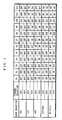
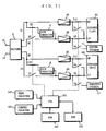
- Fig. 4 is a diagram showing combinations of an on/off state of each of the switches S1-12 controlled by the CPU 101 in Fig. 1 .
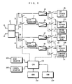
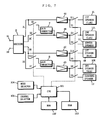
- Fig. 5-Fig. 12 are diagrams showing operating states of the AV amplifier in Fig. 1 corresponding to each of the on/off states shown in Fig. 4 . Operation of the first embodiment will be described below with referring to Fig. 4-Fig. 12 .
- the decoder 2 At the four-channel reproducing time, signals in which multichannel signals are encoded such as a film are inputted from the input terminals 1 L and 1 R. In this case, the decoder 2 separates the inputted signals into four signals and output the four signals as the signal 3L for the L channel, the signal 3C for the C channel, the signal 3R for the R channel and the signal 3S for the S channel. While, at the two-channel stereo reproducing time, two-channel signals in which multichannel signals are not encoded are inputted from the input terminal 1 L and 1 R. In this case, the decoder 2 outputs only the signal 3L for the L channel and the signal 3R for the R channel.
- the above-mentioned state is set up, for example, when the sound is listened with a headphones, not with speakers.
- the CPU 101 sets all of the switches S1-S12 in off states (open states). Accordingly, at this time, the signals outputted from the decoder 2 are not given to any of the speakers but to the headphones which are not shown.
- the mode selector 104 selects a mode for driving the first speaker set of 9L and 9R.
- the CPU 101 sets only the switches S11 and S12 in on states (close states) and sets the other switches in off states.
- the signal 3L for the L channel outputted from the decoder 2 is amplified by the amplifier 4A for the L channel to be given to the first speaker 9L for the L channel.
- the signal 3R for the R channel outputted from the decoder 2 is amplified by the amplifier 4C for the R channel to be given to the first speaker 9R for the R channel.
- the stereo reproduction is performed with the first speaker set of 9L and 9R.
- the channel selector 105 selects the four-channel reproduction, as shown in Fig. 4 , the CPU 101 sets the switches S2, S4, S7, S9, S11 and S12 in on states and sets the other switches in off states.
- the signal 3L for the L channel outputted from the decoder 2 is amplified by the amplifier 4A for the L channel to be given to the first speaker 9L for the L channel.
- the signal 3C for the C channel outputted from the decoder 2 is amplified by the amplifier 4B for the C channel to be given to the center speaker 11.
- the signal 3R for the R channel outputted form the decoder 2 is amplified by the amplifiers 4C for the R channel to be given to the first speaker 9R for the R channel.
- the signal 3S for the S channel outputted from the decoder 2 is amplified by the amplifier 4D for the S channel to be given to the surround speaker 12. Therefore, at this time, the four-channel reproduction is performed with the first speaker set of 9L and 9R, the center speaker 11 and the surround speaker 12.
- the mode selector 104 selects a mode for driving the second speaker set of 10L and 10R.
- the CPU 101 sets only the switches S1 and S6 in on states and sets the other switches in off states.
- the signal 3L for the L channel outputted form the decoder 2 is amplified by the amplifier 4A for the L channel to be given to the second speaker 10L for the L channel.
- the signal 3R for the R channel outputted form the decoder 2 is amplified by the amplifiers 4C for the R channel to be given to the second speaker 10R for the R channel.
- the stereo reproduction is performed with using the second speaker set of 10L and 10R.
- the channel selector 105 selects the four-channel reproduction, as shown in Fig. 4 , the CPU 101 sets the switches S1, S2, S4, S6, S7 and S9 in on states and sets the other switches in off states.
- the signal 3L for the L channel outputted from the decoder 2 is amplified by the amplifier 4A for the L channel to be given to the second speaker 10L for the L channel.
- the signal 3C for the C channel outputted from the decoder 2 is amplified by the amplifier 4B for the C channel to be given to the center speaker 11.
- the signal 3R for the R channel outputted from the decoder 2 is amplified by the amplifier 4C for the R channel to be given to the second speaker 10R for the R channel.
- the signal 3S for the S channel outputted from the decoder 2 is amplified by the amplifier 4D for the S channel to be given to the surround speaker 12. Accordingly, at this time, the four-channel reproduction is performed with using the second speaker set of 10L and 10R, the center speaker 11 and the surround speaker 12.
- the mode selector 104 selects a mode for driving both of the first speaker set of 9L and 9R and the second speaker set of 10L and 10R
- the CPU 101 sets the switches S1, S6, S11 and S12 in on states and sets the other switches in off states.
- the signal 3L for the L channel outputted from the decoder 2 is amplified by the amplifier 4A for the L channel to be given to the first and second speakers 9L and 10L for the L channel in parallel.
- the signal 3R for the R channel outputted from the decoder 2 is amplified by the amplifiers 4C for the R channel to be given to the first and second speakers 9R and 10R for the R channel in parallel. Therefore, at this time, the stereo reproduction is performed with using both of the first and second speaker sets of 9L and 9R and 10L and 10R.
- the channel selector 105 selects the four-channel reproduction, as shown in Fig. 4 , the CPU 101 sets the switches S1, S2, S4, S6, S7, S9, S11 and S12 in on states and sets the other switches in off states. In this case, as shown in Fig.
- the signal 3L for the L channel outputted from then decoder 2 is amplified by the amplifier 4A for the L channel to be given to the first and second speakers 9L and 10L for the L channel.
- the signal 3C for the C channel outputted form the decoder 2 is amplified by the amplifier 4B for the C channel to be given to the center speaker 11.
- the signal 3R for the R channel outputted form the decoder 2 is amplified by the amplifier 4C for the R channel to be given to the first and second speakers 9R and 10R for the R channel.
- the signal 3S for the S channel outputted from the decoder 2 is amplified by the amplifier 4D for the S channel to be given to the surround speaker 12. Accordingly, at this time, the four-channel reproduction is performed with using the first and second speaker sets of 9L and 9R and 10L and 10R, the center speaker 11 and the surround speaker 12.
- the CPU 101 sets the switches S3, S5, S8, S10, S11 and S12 in on states and sets the other switches in off states.
- the signal 3L for the L channel outputted form the decoder 2 is amplified by the amplifier 4A for the L channel to be given to the terminal HF for high-frequency of the bi-wiring speaker 6L for the L channel.
- the signal 3L for the L channel outputted from the decoder 2 is adjusted in level by the gain corrector 7 and amplified by the amplifier 4B for the C channel to be given to the terminal LF for low-frequency of the bi-wiring speaker 6L for the L channel.
- the signal 3R for the R channel outputted from the decoder 2 is amplified by the amplifier 4C for the R channel to be given to the terminal HF for high-frequency of the bi-wiring speaker 6R for the R channel.
- the signal 3R for the R channel outputted from the decoder 2 is adjusted in level by the gain corrector 8 and amplified by the amplifiers 4D for the S channel to be given to the terminal LF for low-frequency of the bi-wiring speaker 6R for the R channel. Accordingly, the bi-wiring speaker set of 6L and 6R can be driven in a high-quality sound stereo mode with the bi-wiring connection using the four amplifiers 4A-4D.
- the gains of the amplifier 4A and 4C are higher than the gains of the amplifiers 4B and 4D, thereby the gain correctors 7 and 8 have positive gains (that is, the gain correctors increase levels of the input signals), however, when the amplifiers 4B and 4D have higher gains, the gain correctors 7 and 8 need to have negative gains, that is, need to decrease the levels of the input signals.
- the CPU 101 sets the switches S1, S2, S4, S6, S7, S9, S11 and S12 in on states and sets the other switches in off states.
- the signal 3L for the L channel outputted from, the decoder 2 is amplified by the amplifier 4A for the L channel to be given to the terminal HF for high-frequency and the terminal LF for low-frequency of the bi-wiring speaker 6L for the L channel in parallel.
- the signal 3C for the C channel outputted from the decoder 2 is amplified by the amplifier 4B for the C channel to be given to the center speaker 11.
- the signal 3R for the R channel outputted from the decoder 2 is amplified by the amplifier 4C for the R channel to be given to the terminal HF for high-frequency and the terminal LF for low-frequency of the bi-wiring speaker 6R for the R channel in parallel.
- the signal 3S for the S channel outputted from the decoder 2 is amplified by the amplifier 4D for the S channel to be given to the surround speaker 12. Accordingly, at this time, the four-channel reproduction is performed with using the bi-wiring speakers 6L and 6R, the center speaker 11 and the surround speaker 12.
- the gain correctors 7 and 8 are provided to equalize the substantial gains of the amplifiers 4A-4D.
- difference of speaker models to be used and difference of sound characteristics of listening rooms needs to be corrected in addition.
- Fig. 13 is a block diagram showing a structure of an AV amplifier according to a second embodiment of the present invention.
- difference from the first embodiment shown in Fig. 1 is that a first and second variable resistors 13 and 14 are connected in series to input sides of the gain correctors 7 and 8. Since other structure is the same as that of the first embodiment, corresponding parts will be assigned with same reference numerals and the explanation will be omitted.
- Gain correcting amounts of the gain correctors 7 and 8 are set higher in advance to make a sum of the gains of the gain corrector 7 and the amplifier 4B for the C channel and a sum of the gains of the gain corrector 8 and the amplifier 4D for the S channel higher than the gains of the amplifier 4A for the L channel and the amplifier 4C for the R channel, respectively, when decreasing amounts of the first and second variable resistors 13 and 14 are set to be minimum.
- the signal 3L for the L channel is adjusted in level by the gain corrector 7 through the first variable resistor 13 and amplified by the amplifier 4B for the C channel to be given to the terminal LF for low-frequency of the bi-wiring speaker 6L for the L channel.
- switching condition on the R channel side is the same as that in the first embodiment (that is, the switches S8, S10 and S12 are turned on and the switches S6, S9 and S12 are turned off), and also the adjustment of the second variable resistor 14 is made as that of the first variable resistor 13.
- the switches S1, S2, S4, S6, S7, S9, S11 and S12 are in on states and the other switches are in off states. Therefore, the gain correctors 7 and 8 are isolated.
- variable resistors 13 and 14 are connected in series to the input sides of the gain correctors 7 and 8 in the above-mentioned second embodiment, the variable resistors may be connected to output sides or provided inside of circuits of the gain correctors 7 and 8. Further, the variable resistors may be taken the place by any methods capable of adjusting the gains of the gain correctors 7 and 8.
- the on/off switches are used in each of the above-described embodiments, it is possible to reduce the number of switches by changing the switches S3 and S4, and S8 and S9 into selector switches and removing the switches S2, S5, S7 and S10 to provide input selection switches for the amplifiers 4B and 4D.
- the switches naturally include electrically connected switches as well as mechanically connected switches.
- the outputs of the amplifiers 4A and 4C are given to the terminals HF for high-frequency of the bi-wiring speakers 6L and 6R, respectively and the outputs of the amplifiers 4B and 4D are given to the terminals LF for low-frequency of the bi-wiring speakers 6L and 6R, respectively in each of the above-described embodiments, however, in a reverse way, the outputs of the amplifiers 4B and 4D may be given to the terminals HF for high-frequency of the bi-wiring speakers 6L and 6R, respectively and the outputs of the amplifiers 4A and 4C may be given to the terminals LF for low-frequency of the bi-wiring speakers 6L and 6R, respectively.
- the first and second variable resistors 13 and 14 can make fine adjustment to the gains at the two-channel stereo reproducing time as necessary, thereby it is possible to correct the deterioration of the frequency characteristics caused by the dispersion in constants of the gain correctors, the difference of the speaker models to be used and the difference of the sound characteristics of the listening rooms.
Landscapes
- Engineering & Computer Science (AREA)
- Power Engineering (AREA)
- Physics & Mathematics (AREA)
- Acoustics & Sound (AREA)
- Signal Processing (AREA)
- Stereophonic System (AREA)
Claims (4)
- Un amplificateur AV capable de commuter sélectivement entre un mode de reproduction multicanal et un mode de reproduction stéréo à deux canaux, comprenant :un décodeur (2) décodant des signaux d'entrée dans lesquels des signaux multicanal sont codés pour délivrer en sortie des signaux multicanal dans le mode de reproduction multicanal, et délivrer un sortie des signaux stéréo sur deux canaux appliqués en entrée lorsqu'ils sont dans le mode de reproduction stéréo sur deux canaux ;des premier à quatrième amplificateurs (4A, 4B, 4C, 4D) pour amplifier des signaux de sortie dudit décodeur ;des première à sixième bornes de sortie (5A, 5B, 5C, 5D, 5E, 5F) pour une connexion à des haut-parleurs ;un sélecteur de mode (104) pour sélectionner soit un mode en bicâblage,dans lequel un premier haut-parleur à bicâblage (6L) doit être connecté à la première et à la seconde bornes de sortie (5A, 5B) dans un mode de connexion à bi-câblage ou biamplification et un second haut-parleur (6R) doit être connecté à la quatrième et à la cinquième bornes de sortie (5D, 5E) dans un mode de connexion à bicâblage ou biamplification, ouun mode qui n'est pas en bi-câblage, dans lequel aucun haut-parleur à bicâblage ne doit être relié à aucune des première à sixième bornes de sortie dans un mode de connexion à biamplification ;un sélecteur de canal (105) pour sélectionner soit ledit mode de reproduction multicanal soit ledit mode de reproduction stéréo sur deux canaux ; etun circuit de commutation (S1, S2 ... S12) pour commuter un schéma de connexion entre ledit décodeur et lesdits premier à quatrième amplificateurs (4A, 4B, 4C, 4D) et entre lesdits premier et quatrième amplificateurs et lesdites première à sixième bornes de sortie conformément à une sélection de mode par ledit sélecteur de mode etledit sélecteur de canal, dans lequelledit circuit de commutation :(a) lorsque le mode non en bicâblage et le mode de reproduction multicanal sont sélectionnés, commute ledit schéma de connexion de sorte qu'un signal pour le canal G soit amplifié par le premier amplificateur (4A) et un signal pour le canal D soit amplifié par le troisième amplificateur (4C), d'autres signaux multicanal soient respectivement amplifiés par les second et quatrième amplificateurs (4B, 4D), et le signal produit en sortie par le premier amplificateur (4A) soit délivré au moins à l'une de la première et de la seconde bornes (5A, 58), le signal produit en sortie du troisième amplificateur (4C) vers au moins l'une de la quatrième et cinquième bornes (5D, 5E), et les signaux délivrés en sortie des second et quatrième amplificateurs (4B, 4D) vers la troisième et sixième bornes de sortie (5C, 5F), respectivement (Figures 6, 8 et 10) ;(b) lorsque le mode en bicâblage et le mode de reproduction stéréo sur deux canaux sont sélectionnés, commute ledit schéma de connexion de sorte que parmi les signaux stéréo sur deux canaux, un signal pour le canal G soit amplifié en parallèle par les premier et second amplificateurs (4A, 4B), et un signal pour le canal D soit amplifié en parallèle par le troisième et quatrième amplificateurs (4C, 4D), et les signaux de sortie des premier et second amplificateurs (4A, 4B) soient respectivement délivrés à la première et seconde bornes de sortie (5A, 58) et les signaux de sortie du troisième et quatrième amplificateurs (4C, 4D) soient respectivement délivrés à la quatrième et cinquième bornes de sortie (5D, 5E) (Figure 11) ; et(c) lorsque le mode en bicâblage et le mode de reproduction multicanal sont sélectionnés, commute ledit schéma de connexion de sorte qu'un signal pour le canal G soit amplifié par le premier amplificateur (4A) et un signal pour le canal D soit amplifié par le troisième amplificateur (4C), les autres signaux multicanal étant respectivement amplifiés par les second et quatrième amplificateurs (4B, 4D) et le signal produit en sortie par chacun des premier et troisième amplificateurs (4A, 4C) soit respectivement délivré à la première et à la seconde bornes (5A, 5B) et à la quatrième et cinquième bornes de sortie (5D, 5E), et la sortie des second et quatrième amplificateurs (4B, 4D) soit respectivement délivrée à la troisième (5C) et à la sixième (5F) bornes (Figure 12).
- L'amplificateur (av) selon la revendication 1, comprenant en outre :un premier correcteur de gain (7) pour corriger une différence entre les gains desdits premier et second amplificateurs (4A, 4B) ; etun second correcteur de gain pour corriger une différence entre les gains desdits troisième et quatrième amplificateurs (4C, 4D), dans lequel ledit circuit de commutation commute ledit schéma de connexion de sorte que lesdits premier et second correcteurs de gain (7, 8) soient activés lorsque le mode en bicâblage et le mode de reproduction stéréo sur deux canaux sont sélectionnés.
- L'amplificateur (av) selon la revendication 2, dans lequel ledit premier correcteur de gain (7) corrige les gains de sorte qu'un gain que présente un signal de sortie dudit premier amplificateur (4A) par rapport audit signal pour le canal G soit presque égal à un gain que présente un signal de sortie dudit second amplificateur (4B) par rapport audit signal pour le canal G, et
ledit second correcteur de gain (8) corrige les gains de sorte qu'un gain que présente un signal de sortie dudit troisième amplificateur (4C) par rapport auxdits signaux pour le canal D soit presque égal à un gain que présente un signal de sortie dudit quatrième amplificateur (4D) par rapport audit signal pour le canal D. - L'amplificateur AV selon la revendication 3, dans lequel lesdits premier et second correcteurs de gain (7, 8) comprennent des moyens d'ajustement fin pour l'ajustement fin des quantités de correction de gain.
Applications Claiming Priority (3)
| Application Number | Priority Date | Filing Date | Title |
|---|---|---|---|
| JP5452797 | 1997-03-10 | ||
| JP5452797 | 1997-03-10 | ||
| JP54527/97 | 1997-03-10 |
Publications (3)
| Publication Number | Publication Date |
|---|---|
| EP0866638A2 EP0866638A2 (fr) | 1998-09-23 |
| EP0866638A3 EP0866638A3 (fr) | 2004-11-03 |
| EP0866638B1 true EP0866638B1 (fr) | 2011-06-15 |
Family
ID=12973143
Family Applications (1)
| Application Number | Title | Priority Date | Filing Date |
|---|---|---|---|
| EP98104167A Expired - Lifetime EP0866638B1 (fr) | 1997-03-10 | 1998-03-09 | Amplificateur audiovisuel |
Country Status (3)
| Country | Link |
|---|---|
| US (1) | US6167140A (fr) |
| EP (1) | EP0866638B1 (fr) |
| CN (1) | CN1110986C (fr) |
Cited By (1)
| Publication number | Priority date | Publication date | Assignee | Title |
|---|---|---|---|---|
| EP4618593A4 (fr) * | 2022-12-29 | 2026-02-25 | Honor Device Co Ltd | Circuit audio et équipement terminal |
Families Citing this family (28)
| Publication number | Priority date | Publication date | Assignee | Title |
|---|---|---|---|---|
| JP3573981B2 (ja) * | 1998-11-17 | 2004-10-06 | パイオニア株式会社 | オーディオ信号処理用集積回路 |
| CN2382187Y (zh) * | 1999-05-21 | 2000-06-07 | 朱望文 | 模式效果可调校式多用途扬声器装置 |
| US6690431B1 (en) * | 1999-08-02 | 2004-02-10 | Mg International (Zhong Shan) Co., Ltd. | Audio/video amplifier with the function of automatic turning on/off |
| JP2002064900A (ja) * | 2000-08-18 | 2002-02-28 | Sony Corp | 多チャンネル音響信号再生装置 |
| US20020131611A1 (en) * | 2001-03-13 | 2002-09-19 | Hoover Alan Anderson | `Audio surround sound power management switching |
| US7668317B2 (en) * | 2001-05-30 | 2010-02-23 | Sony Corporation | Audio post processing in DVD, DTV and other audio visual products |
| KR20040091110A (ko) * | 2002-03-07 | 2004-10-27 | 코닌클리케 필립스 일렉트로닉스 엔.브이. | 사용자 제어 다중-채널 오디오 변환 시스템 |
| US7305097B2 (en) * | 2003-02-14 | 2007-12-04 | Bose Corporation | Controlling fading and surround signal level |
| US20050185806A1 (en) * | 2003-02-14 | 2005-08-25 | Salvador Eduardo T. | Controlling fading and surround signal level |
| JP4264037B2 (ja) * | 2004-06-30 | 2009-05-13 | 株式会社ケンウッド | 音響装置および再生モード設定方法 |
| JP4674474B2 (ja) * | 2005-02-24 | 2011-04-20 | パナソニック株式会社 | パラレル駆動バイアンプ切換回路 |
| JP4720405B2 (ja) * | 2005-09-27 | 2011-07-13 | 船井電機株式会社 | 音声信号処理装置 |
| JPWO2007052625A1 (ja) * | 2005-10-31 | 2009-04-30 | パナソニック株式会社 | 映像音声視聴システム |
| JP4197040B2 (ja) * | 2007-05-11 | 2008-12-17 | オンキヨー株式会社 | マルチチャンネル増幅器 |
| US8649527B2 (en) | 2007-12-14 | 2014-02-11 | Freescale Semiconductor, Inc. | Amplifier circuit, electronic device, method for configuring an amplifier circuit |
| TWI403187B (zh) * | 2008-07-04 | 2013-07-21 | Acer Inc | 擴音系統、裝置以及方法 |
| CN101394154B (zh) * | 2008-10-10 | 2010-09-29 | 南通大学 | 自动增益双通道音频前置放大器 |
| US8494183B2 (en) * | 2009-02-03 | 2013-07-23 | Onkyo Corporation | Audio processing apparatus |
| JP4471030B1 (ja) * | 2009-02-03 | 2010-06-02 | オンキヨー株式会社 | 音声処理装置 |
| GB2477295B (en) * | 2010-01-28 | 2013-10-02 | Gp Acoustics Uk Ltd | Loudspeaker system |
| US9426574B2 (en) * | 2010-03-19 | 2016-08-23 | Bose Corporation | Automatic audio source switching |
| JP4997659B2 (ja) | 2010-04-02 | 2012-08-08 | オンキヨー株式会社 | 音声処理装置 |
| JP5245186B2 (ja) * | 2011-02-02 | 2013-07-24 | オンキヨー株式会社 | 音声処理装置 |
| JP5477397B2 (ja) * | 2012-01-25 | 2014-04-23 | オンキヨー株式会社 | 音声処理装置 |
| JP5477404B2 (ja) * | 2012-02-10 | 2014-04-23 | オンキヨー株式会社 | 音声処理装置 |
| US20160337755A1 (en) * | 2015-05-13 | 2016-11-17 | Paradigm Electronics Inc. | Surround speaker |
| KR102534861B1 (ko) * | 2016-12-23 | 2023-05-22 | 삼성전자주식회사 | 앰프 모듈 및 그 제어 방법 |
| EP3606101B1 (fr) * | 2017-03-22 | 2025-02-19 | Yamaha Corporation | Dispositif de traitement de signal |
Family Cites Families (8)
| Publication number | Priority date | Publication date | Assignee | Title |
|---|---|---|---|---|
| GB1416631A (en) * | 1972-05-30 | 1975-12-03 | Nippon Columbia | Discrete 4-channel stereo recording and/or reproducing system |
| JPS5325481Y2 (fr) * | 1972-09-21 | 1978-06-29 | ||
| JPS5320224Y2 (fr) * | 1973-08-01 | 1978-05-27 | ||
| US4468806A (en) * | 1983-05-13 | 1984-08-28 | Gaulden Joe L | Stero speaker mixer |
| US5199075A (en) * | 1991-11-14 | 1993-03-30 | Fosgate James W | Surround sound loudspeakers and processor |
| DE4328620C1 (de) * | 1993-08-26 | 1995-01-19 | Akg Akustische Kino Geraete | Verfahren zur Simulation eines Raum- und/oder Klangeindrucks |
| US5399986A (en) * | 1993-12-20 | 1995-03-21 | Yen; Wailit | Isolated multi-output power amplifier |
| DE19539034A1 (de) * | 1995-10-19 | 1997-04-24 | Nokia Deutschland Gmbh | Audioverstärkeranordnung für mehr als zwei Wiedergabekanäle |
-
1998
- 1998-03-09 US US09/036,689 patent/US6167140A/en not_active Expired - Lifetime
- 1998-03-09 EP EP98104167A patent/EP0866638B1/fr not_active Expired - Lifetime
- 1998-03-10 CN CN98105481A patent/CN1110986C/zh not_active Expired - Fee Related
Cited By (1)
| Publication number | Priority date | Publication date | Assignee | Title |
|---|---|---|---|---|
| EP4618593A4 (fr) * | 2022-12-29 | 2026-02-25 | Honor Device Co Ltd | Circuit audio et équipement terminal |
Also Published As
| Publication number | Publication date |
|---|---|
| EP0866638A3 (fr) | 2004-11-03 |
| US6167140A (en) | 2000-12-26 |
| CN1194533A (zh) | 1998-09-30 |
| CN1110986C (zh) | 2003-06-04 |
| EP0866638A2 (fr) | 1998-09-23 |
Similar Documents
| Publication | Publication Date | Title |
|---|---|---|
| EP0866638B1 (fr) | Amplificateur audiovisuel | |
| CN1227951C (zh) | 用于环绕声环境的音频增强系统和方法 | |
| EP1219140B1 (fr) | Dispositif de correction acoustique | |
| US5333201A (en) | Multi dimensional sound circuit | |
| US5319713A (en) | Multi dimensional sound circuit | |
| CN1284415C (zh) | 音频再现设备和方法 | |
| US5708719A (en) | In-home theater surround sound speaker system | |
| US4612663A (en) | Multichannel audio reproduction system | |
| US5265166A (en) | Multi-channel sound simulation system | |
| US6281749B1 (en) | Sound enhancement system | |
| NL9002174A (nl) | Meerkanaalsaudioreproduktie-apparaat. | |
| JP3436681B2 (ja) | Avアンプ | |
| WO1999026454A1 (fr) | Systeme de simulation audio pour basses frequences | |
| AU748414B2 (en) | Post-amplification stereophonic to surround sound decoding circuit | |
| US5123051A (en) | Sound field reproducing apparatus | |
| JP2000197182A (ja) | ラウドネス制御方法および装置 | |
| EP1471771A2 (fr) | Appareil de reproduction audio et récepteur vidéo | |
| JP2003158800A (ja) | 多チャンネルオーディオ再生装置 | |
| JP2002112382A (ja) | 音響再生装置 | |
| JPH0937381A (ja) | 出力レベル切り換え回路 | |
| JP3508591B2 (ja) | オーディオ用電力増幅装置 | |
| JP2005045533A (ja) | 音声再生装置 | |
| JPH04273800A (ja) | 音像定位装置及び音像定位信号処理方法 | |
| JPH08186891A (ja) | スピ−カユニットの駆動方法 | |
| JP2599438Y2 (ja) | 音声信号処理装置 |
Legal Events
| Date | Code | Title | Description |
|---|---|---|---|
| PUAI | Public reference made under article 153(3) epc to a published international application that has entered the european phase |
Free format text: ORIGINAL CODE: 0009012 |
|
| AK | Designated contracting states |
Kind code of ref document: A2 Designated state(s): AT BE CH DE DK ES FI FR GB GR IE IT LI LU MC NL PT SE |
|
| AX | Request for extension of the european patent |
Free format text: AL;LT;LV;MK;RO;SI |
|
| PUAL | Search report despatched |
Free format text: ORIGINAL CODE: 0009013 |
|
| AK | Designated contracting states |
Kind code of ref document: A3 Designated state(s): AT BE CH DE DK ES FI FR GB GR IE IT LI LU MC NL PT SE |
|
| AX | Request for extension of the european patent |
Extension state: AL LT LV MK RO SI |
|
| RIC1 | Information provided on ipc code assigned before grant |
Ipc: 7H 03F 3/68 B Ipc: 7H 04S 3/02 B Ipc: 7H 04R 5/04 A |
|
| 17P | Request for examination filed |
Effective date: 20050316 |
|
| AKX | Designation fees paid |
Designated state(s): DE GB |
|
| RAP1 | Party data changed (applicant data changed or rights of an application transferred) |
Owner name: PANASONIC CORPORATION |
|
| GRAP | Despatch of communication of intention to grant a patent |
Free format text: ORIGINAL CODE: EPIDOSNIGR1 |
|
| GRAS | Grant fee paid |
Free format text: ORIGINAL CODE: EPIDOSNIGR3 |
|
| GRAA | (expected) grant |
Free format text: ORIGINAL CODE: 0009210 |
|
| AK | Designated contracting states |
Kind code of ref document: B1 Designated state(s): DE GB |
|
| REG | Reference to a national code |
Ref country code: GB Ref legal event code: FG4D |
|
| REG | Reference to a national code |
Ref country code: DE Ref legal event code: R096 Ref document number: 69842307 Country of ref document: DE Effective date: 20110721 |
|
| PLBE | No opposition filed within time limit |
Free format text: ORIGINAL CODE: 0009261 |
|
| STAA | Information on the status of an ep patent application or granted ep patent |
Free format text: STATUS: NO OPPOSITION FILED WITHIN TIME LIMIT |
|
| 26N | No opposition filed |
Effective date: 20120316 |
|
| REG | Reference to a national code |
Ref country code: DE Ref legal event code: R097 Ref document number: 69842307 Country of ref document: DE Effective date: 20120316 |
|
| PGFP | Annual fee paid to national office [announced via postgrant information from national office to epo] |
Ref country code: GB Payment date: 20130306 Year of fee payment: 16 Ref country code: DE Payment date: 20130306 Year of fee payment: 16 |
|
| REG | Reference to a national code |
Ref country code: DE Ref legal event code: R084 Ref document number: 69842307 Country of ref document: DE |
|
| REG | Reference to a national code |
Ref country code: GB Ref legal event code: 746 Effective date: 20130617 |
|
| REG | Reference to a national code |
Ref country code: DE Ref legal event code: R084 Ref document number: 69842307 Country of ref document: DE Effective date: 20130701 |
|
| REG | Reference to a national code |
Ref country code: DE Ref legal event code: R119 Ref document number: 69842307 Country of ref document: DE |
|
| GBPC | Gb: european patent ceased through non-payment of renewal fee |
Effective date: 20140309 |
|
| REG | Reference to a national code |
Ref country code: DE Ref legal event code: R119 Ref document number: 69842307 Country of ref document: DE Effective date: 20141001 |
|
| PG25 | Lapsed in a contracting state [announced via postgrant information from national office to epo] |
Ref country code: DE Free format text: LAPSE BECAUSE OF NON-PAYMENT OF DUE FEES Effective date: 20141001 Ref country code: GB Free format text: LAPSE BECAUSE OF NON-PAYMENT OF DUE FEES Effective date: 20140309 |