EP0866938B1 - Deckenradiator - Google Patents
Deckenradiator Download PDFInfo
- Publication number
- EP0866938B1 EP0866938B1 EP97921720A EP97921720A EP0866938B1 EP 0866938 B1 EP0866938 B1 EP 0866938B1 EP 97921720 A EP97921720 A EP 97921720A EP 97921720 A EP97921720 A EP 97921720A EP 0866938 B1 EP0866938 B1 EP 0866938B1
- Authority
- EP
- European Patent Office
- Prior art keywords
- pipe
- ceiling
- heating
- radiant
- holder
- Prior art date
- Legal status (The legal status is an assumption and is not a legal conclusion. Google has not performed a legal analysis and makes no representation as to the accuracy of the status listed.)
- Expired - Lifetime
Links
- 238000010438 heat treatment Methods 0.000 claims abstract description 15
- 229910052782 aluminium Inorganic materials 0.000 claims abstract description 3
- XAGFODPZIPBFFR-UHFFFAOYSA-N aluminium Chemical compound [Al] XAGFODPZIPBFFR-UHFFFAOYSA-N 0.000 claims abstract description 3
- 238000001816 cooling Methods 0.000 claims abstract description 3
- 238000007654 immersion Methods 0.000 claims description 5
- 239000002826 coolant Substances 0.000 claims description 3
- 229910052751 metal Inorganic materials 0.000 claims description 3
- 239000002184 metal Substances 0.000 claims description 3
- 239000004411 aluminium Substances 0.000 claims 1
- 238000001125 extrusion Methods 0.000 claims 1
- 239000000463 material Substances 0.000 claims 1
- 239000004033 plastic Substances 0.000 claims 1
- 229920003023 plastic Polymers 0.000 claims 1
- 230000005855 radiation Effects 0.000 abstract description 4
- 239000000843 powder Substances 0.000 abstract 1
- 241000047428 Halter Species 0.000 description 5
- 239000007789 gas Substances 0.000 description 5
- 238000009413 insulation Methods 0.000 description 3
- 229910000831 Steel Inorganic materials 0.000 description 2
- 239000010959 steel Substances 0.000 description 2
- XLYOFNOQVPJJNP-UHFFFAOYSA-N water Substances O XLYOFNOQVPJJNP-UHFFFAOYSA-N 0.000 description 2
- 241001156002 Anthonomus pomorum Species 0.000 description 1
- 101100293261 Mus musculus Naa15 gene Proteins 0.000 description 1
- 239000011324 bead Substances 0.000 description 1
- 238000005422 blasting Methods 0.000 description 1
- 238000009826 distribution Methods 0.000 description 1
- 238000004519 manufacturing process Methods 0.000 description 1
- 230000002787 reinforcement Effects 0.000 description 1
Images


Classifications
-
- F—MECHANICAL ENGINEERING; LIGHTING; HEATING; WEAPONS; BLASTING
- F24—HEATING; RANGES; VENTILATING
- F24D—DOMESTIC- OR SPACE-HEATING SYSTEMS, e.g. CENTRAL HEATING SYSTEMS; DOMESTIC HOT-WATER SUPPLY SYSTEMS; ELEMENTS OR COMPONENTS THEREFOR
- F24D5/00—Hot-air central heating systems; Exhaust gas central heating systems
- F24D5/06—Hot-air central heating systems; Exhaust gas central heating systems operating without discharge of hot air into the space or area to be heated
- F24D5/08—Hot-air central heating systems; Exhaust gas central heating systems operating without discharge of hot air into the space or area to be heated with hot air led through radiators
-
- F—MECHANICAL ENGINEERING; LIGHTING; HEATING; WEAPONS; BLASTING
- F24—HEATING; RANGES; VENTILATING
- F24D—DOMESTIC- OR SPACE-HEATING SYSTEMS, e.g. CENTRAL HEATING SYSTEMS; DOMESTIC HOT-WATER SUPPLY SYSTEMS; ELEMENTS OR COMPONENTS THEREFOR
- F24D3/00—Hot-water central heating systems
- F24D3/12—Tube and panel arrangements for ceiling, wall, or underfloor heating
- F24D3/16—Tube and panel arrangements for ceiling, wall, or underfloor heating mounted on, or adjacent to, a ceiling, wall or floor
- F24D3/165—Suspended radiant heating ceiling
-
- F—MECHANICAL ENGINEERING; LIGHTING; HEATING; WEAPONS; BLASTING
- F24—HEATING; RANGES; VENTILATING
- F24F—AIR-CONDITIONING; AIR-HUMIDIFICATION; VENTILATION; USE OF AIR CURRENTS FOR SCREENING
- F24F5/00—Air-conditioning systems or apparatus not covered by F24F1/00 or F24F3/00, e.g. using solar heat or combined with household units such as an oven or water heater
- F24F5/0089—Systems using radiation from walls or panels
-
- F—MECHANICAL ENGINEERING; LIGHTING; HEATING; WEAPONS; BLASTING
- F24—HEATING; RANGES; VENTILATING
- F24F—AIR-CONDITIONING; AIR-HUMIDIFICATION; VENTILATION; USE OF AIR CURRENTS FOR SCREENING
- F24F5/00—Air-conditioning systems or apparatus not covered by F24F1/00 or F24F3/00, e.g. using solar heat or combined with household units such as an oven or water heater
- F24F5/0089—Systems using radiation from walls or panels
- F24F5/0092—Systems using radiation from walls or panels ceilings, e.g. cool ceilings
-
- Y—GENERAL TAGGING OF NEW TECHNOLOGICAL DEVELOPMENTS; GENERAL TAGGING OF CROSS-SECTIONAL TECHNOLOGIES SPANNING OVER SEVERAL SECTIONS OF THE IPC; TECHNICAL SUBJECTS COVERED BY FORMER USPC CROSS-REFERENCE ART COLLECTIONS [XRACs] AND DIGESTS
- Y02—TECHNOLOGIES OR APPLICATIONS FOR MITIGATION OR ADAPTATION AGAINST CLIMATE CHANGE
- Y02B—CLIMATE CHANGE MITIGATION TECHNOLOGIES RELATED TO BUILDINGS, e.g. HOUSING, HOUSE APPLIANCES OR RELATED END-USER APPLICATIONS
- Y02B30/00—Energy efficient heating, ventilation or air conditioning [HVAC]
Definitions
- the usual radiant ceiling heaters consist of one wide, corrugated radiant panel belt made of sheet steel, in the a pipe register through which water flows is welded in. Often one is used to limit the heat emission Thermal insulation applied.
- the usual directly heated radiation pipes consist of a reflector shining towards the floor, below arranged heating tube is illuminated by what hot exhaust gases from an oil or gas forced draft burner flow, and a suction fan.
- Both versions have the disadvantage that the Illuminated floor area in relation to the hot one Beam area of the ceiling radiators is very small, which is at higher heating temperatures very disadvantageous to the Affects comfort.
- the manufacturing method is out many welded components, such as beads Sheet metal plates with side bends, flow tubes and pipe distributors, reinforcement profiles with Mounting holes and face plates, very complex.
- GB 2 262 548 A Ceiling radiator of the type mentioned above, in which one through which the heating or cooling medium flows Flow tube down from a radiation area is shadowed. The side surfaces are too shadowed.
- a wall radiator is known from FR - A - 1 553 142, which is installed vertically in a recess in a wall is. It also has only one outside radiation surface, all other areas are shaded.
- a flow tube is also in Components installed, the most diverse configurations for blasting.
- the present invention is based on the object Because of the good thermal insulation that is common today new ceiling radiators adapted to the times much smaller dimensions and a smaller one Dead weight and a much better heat distribution to create with fewer drafts.
- the at least three Radial plates protrude radially.
- the new hot water ceiling radiator is mainly used as X-shaped extruded profile made of aluminum. Due to the diagonal arrangement of eight arched Radiant areas on a central heating pipe are essential smaller designs with great sag resistance and low weight possible. In addition, a U-shaped Air duct profile can be pushed on.
- FIG. 1 are in a room below a ceiling two suspended ceiling radiators 1 are provided, which are X-shaped are designed and radiate heat or cold.
- FIG. 2 there is an X-shaped ceiling radiator on one Holder 19 attached and via this holder 19 with the Room ceiling 18 connected. Is between two radiant panels thermal insulation inserted. Furthermore, the ceiling radiator covered by a reflector 17.
- FIG. 3 it can be seen that the ceiling radiator 1 a heater flow 13 and a heater return 14 adjoined.
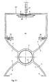
- FIG 4 is an extruded X-shaped Ceiling radiator shown in original size with a Heating tube 2 3.2 cm (1 1/4 ") and four radiant panels 3, which are domed are trained. In this way there are eight domed ones Beam surfaces formed. At the end, each radiant panel points a stacking and fastening strip 5. The Fastening strips 5 of two adjacent radiant panels 3 are each in a groove of a holding profile 19th inserted.
- the inner surface of the heating tube 2 (flow tube) is with a corrugation 12 provided.
- the radiant panels are flat. End ⁇ rtig these radiant panels each have a fastening profile 20 for fixing to a holder 19.
- the flow tube consists of several Tubes 2 ', which together form a tube register 9.
- the Pipes 2 ' are connected to one another by transverse bores 10.
- the radiant panels also can be curved in the same direction. Furthermore is an immersion tube 21 is inserted into the flow tube 2.
- the ceiling radiator 1 according to FIG. 9 has a large one Heating pipe 2 for hot air or hot exhaust gases to which Connect twelve beam shadow-free beam surfaces.
- Four the radiant panels also have fastening strips 5, two mounting strips 5 overlap the holder.
- a ceiling radiator forms accordingly Figure 4 together with a U-shaped profile 23 Air duct 24 off.
- This has a mounting groove 25 for the holder 19.
- the U-shaped profile has two further fastening grooves 25 for receiving the Fastening strips 5 on the radiant panels 3. These Fastening strips 5 are inserted into the grooves 25.
- the ceiling radiators shown in Figures 1 to 11 have the common feature that with the smallest dimensions and low weight an optimal deflection strength is achieved.
- an optimal deflection strength is achieved.
Landscapes
- Engineering & Computer Science (AREA)
- General Engineering & Computer Science (AREA)
- Mechanical Engineering (AREA)
- Chemical & Material Sciences (AREA)
- Combustion & Propulsion (AREA)
- Sustainable Development (AREA)
- Physics & Mathematics (AREA)
- Life Sciences & Earth Sciences (AREA)
- Thermal Sciences (AREA)
- Domestic Hot-Water Supply Systems And Details Of Heating Systems (AREA)
- Vehicle Interior And Exterior Ornaments, Soundproofing, And Insulation (AREA)
- Central Heating Systems (AREA)
- Devices For Blowing Cold Air, Devices For Blowing Warm Air, And Means For Preventing Water Condensation In Air Conditioning Units (AREA)
- Buildings Adapted To Withstand Abnormal External Influences (AREA)
- Air-Conditioning For Vehicles (AREA)
Description
- wobei das Durchflussrohr mittels des Halters unterhalb einer Raumdecke aufhängbar ist,
- wobei von dem Durchflussrohr zumindest drei bogenartige oder flache Strahlplatten strahlenförmig abstehen,
- wobei die Strahlplatten profilierte oder glatte Oberflächen aufweisen,
- wobei die Strahlplatten mit Befestigungsleisten oder Befestigungsprofilen für den Halter versehen sind,
- und wobei zumindest eine der drei Strahlplatten mittels einer der Befestigungsleisten oder eines der Befestigungsprofile an dem Halter befestigt ist.
Claims (9)
- Deckenradiator für die Beheizung bzw. Kühlung von Räumen aller Art aus zumindest einem Durchflussrohr (2) für ein Heiz- oder Kühlmedium und einem Halter (19, 23),dadurch gekennzeichnet,wobei das Durchflussrohr (2) mittels des Halters (19, 23) unterhalb einer Raumdecke aufhängbar ist,wobei von dem Durchflussrohr (2) zumindest drei bogenartige oder flache Strahlplatten strahlenförmig abstehen,wobei die Strahlplatten profilierte oder glatte Oberflächen aufweisen,wobei die Strahlplatten mit Befestigungsleisten (5) oder Befestigungsprofilen (20) für den Halter versehen sind,und wobei zumindest eine der drei Strahlplatten mittels einer der Befestigungsleisten (5) oder eines der Befestigungsprofile (20) an dem Halter (19, 23) befestigt ist,dass die zumindest drei Strahlplatten radial abstehen.
- Deckenradiator nach Anspruch 1, dadurch gekennzeichnet, dass in dem Durchflussrohr (2) ein Tauchrohr (21) angeordnet ist.
- Deckenradiator nach Anspruch 2, dadurch gekennzeichnet, dass das Tauchrohr (21) mit einem Gas- oder Ölbrenner (15) in Verbindung steht.
- Deckenradiator nach wenigstens einem der Ansprüche 1 bis 3, dadurch gekennzeichnet, dass das Durchflussrohr (2) zusammen mit den Strahlplatten (3) im Strangpressverfahren aus Aluminium oder Kunststoff hergestellt ist.
- Deckenradiator nach wenigstens einem der Ansprüche 1 bis 3, dadurch gekennzeichnet, dass das Durchflussrohr (2) mit aus abgewinkelten und gesickten Blechplatten (8) hergestellten Strahlplatten (3) verbunden ist.
- Deckenradiator nach wenigsten einem der Ansprüche 1 bis 5, dadurch gekennzeichnet, dass an zumindest einer Strahlfläche (4) zumindest ein elektrisches Heizband (11) angeordnet ist.
- Deckenradiator nach wenigstens einem der Ansprüche 1 bis 6, dadurch gekennzeichnet, dass das Durchflussrohr (2) innenseitig eine Riffelung (12) aufweist.
- Deckenradiator nach wenigstens einem der Ansprüche 1 bis 7, dadurch gekennzeichnet, dass in das Durchflussrohr (2) Profilstäbe oder Spiralen als Turbulatoren (22) eingelegt sind.
- Deckenradiator nach wenigstens einem der Ansprüche 1 bis 8, dadurch gekennzeichnet, dass zwei Strahlplatten (3) zusammen mit dem Halter (19, 23), welcher ein U-Profil (23) umfasst, einen Luftkanal (24) ausbilden.
Applications Claiming Priority (3)
| Application Number | Priority Date | Filing Date | Title |
|---|---|---|---|
| DE19617718A DE19617718A1 (de) | 1996-04-24 | 1996-04-24 | Deckenradiator |
| DE19617718 | 1996-04-24 | ||
| PCT/EP1997/002069 WO1997040321A1 (de) | 1996-04-24 | 1997-04-23 | Deckenradiator |
Publications (2)
| Publication Number | Publication Date |
|---|---|
| EP0866938A1 EP0866938A1 (de) | 1998-09-30 |
| EP0866938B1 true EP0866938B1 (de) | 2003-04-09 |
Family
ID=7793192
Family Applications (1)
| Application Number | Title | Priority Date | Filing Date |
|---|---|---|---|
| EP97921720A Expired - Lifetime EP0866938B1 (de) | 1996-04-24 | 1997-04-23 | Deckenradiator |
Country Status (9)
| Country | Link |
|---|---|
| US (1) | US5950720A (de) |
| EP (1) | EP0866938B1 (de) |
| AT (1) | ATE237104T1 (de) |
| AU (1) | AU2768997A (de) |
| CA (1) | CA2203202A1 (de) |
| DE (2) | DE19617718A1 (de) |
| DK (1) | DK0866938T3 (de) |
| ES (1) | ES2196330T3 (de) |
| WO (1) | WO1997040321A1 (de) |
Cited By (4)
| Publication number | Priority date | Publication date | Assignee | Title |
|---|---|---|---|---|
| DE102005061069B3 (de) * | 2005-12-21 | 2007-08-09 | Klapka, Hans | Deckenradiator |
| WO2013030356A2 (de) | 2011-09-02 | 2013-03-07 | Uwe Klix | Deckenradiator |
| WO2016097066A1 (de) | 2014-12-19 | 2016-06-23 | Uwe Klix | Deckenradiatorprofil |
| DE102008020422B4 (de) * | 2008-04-24 | 2018-02-15 | Phoenix Metall Gmbh | Heiz- oder Kühlelement mit einer Anschlussverrohrung |
Families Citing this family (17)
| Publication number | Priority date | Publication date | Assignee | Title |
|---|---|---|---|---|
| NL1008380C2 (nl) * | 1998-02-20 | 1999-08-24 | Stork Installatietechniek Ensc | Plaatsruimte voor een toeschouwer van een evenement, verwarmingsmiddelen voor een dergelijke plaatsruimte, en tribune voorzien van dergelijke plaatsruimten. |
| DK79298A (da) * | 1998-06-08 | 1999-12-09 | Norsk Hydro As | Profil for køling af brændstof, en brændstofledning samt en fremgangsmåde til fremstilling heraf |
| US6889911B2 (en) * | 2000-05-31 | 2005-05-10 | Vent-Rite Valve Corp. | Radiator with cover and mounting board and method of installation |
| US6550688B1 (en) * | 2000-05-31 | 2003-04-22 | Smiths Environmental Products Ltd. | Radiator with cover and mounting board and method of installation |
| DE10328288A1 (de) * | 2003-06-23 | 2005-01-20 | Vasco Bvba | Profilkörper mit Längsrippen und Teilrippen |
| DE102009004785B4 (de) * | 2009-01-13 | 2019-05-29 | Frenger Systemen BV Heiz- und Kühltechnik GmbH | Strahlflächenaufbau |
| US8756857B2 (en) | 2011-01-14 | 2014-06-24 | Technologies Holdings Corp. | Hydronic heating system and method for pest control |
| US8720109B2 (en) | 2011-01-25 | 2014-05-13 | Technologies Holdings Corp. | Portable heating system for pest control |
| US10082300B2 (en) * | 2013-08-30 | 2018-09-25 | Barcol-Air, Ltd. | Radiant heating and cooling system |
| US20150338112A1 (en) * | 2014-05-26 | 2015-11-26 | Infosys Ltd | Monolithic radiant panel and system thereof |
| US10745216B2 (en) * | 2015-04-01 | 2020-08-18 | Pacific Western Timbers, Inc. | Stickers for drying and/or curing materials |
| CN105020821B (zh) * | 2015-07-30 | 2018-02-23 | 浙江大学 | 反射式辐射供冷系统 |
| DE102016005263A1 (de) * | 2016-04-29 | 2017-11-02 | Kübler Gmbh | Infrarot-Heizeinrichtung zum Beheizen eines Gebäudes sowie Verfahren zum Beheizen eines Gebäudes mit einer solchen Infrarot-Heizeinrichtung |
| DE102016111759A1 (de) * | 2016-06-27 | 2017-12-28 | Lukas Jaworek | Aufsatz zur Wärmeabfuhr für einen Heizkörper |
| DE102020204727A1 (de) * | 2020-04-15 | 2021-10-21 | Kermi Gmbh | Deckenstrahlelemente |
| EP4089335B1 (de) * | 2021-05-14 | 2023-11-29 | Allfest GmbH | Deckenradiator mit einer sternförmigen querschnittsform |
| US20240175585A1 (en) * | 2021-08-27 | 2024-05-30 | Kübler Gmbh | Stationary infrared radiator |
Family Cites Families (10)
| Publication number | Priority date | Publication date | Assignee | Title |
|---|---|---|---|---|
| FR1553142A (de) * | 1967-12-01 | 1969-01-10 | ||
| US4301862A (en) * | 1979-01-24 | 1981-11-24 | Mcalister Roy E | Multiple fluid medium system and improved heat exchanger utilized therein |
| US4341346A (en) * | 1980-07-30 | 1982-07-27 | Alcan Aluminium (U.K.) Ltd. | Radiators for use in hot water central heating systems |
| FR2615932A1 (fr) * | 1987-05-27 | 1988-12-02 | Air Tech Franco Suisse | Procede et dispositif de chauffage par rayonnement |
| US5363908A (en) * | 1990-02-24 | 1994-11-15 | Koester Helmut | Heating and cooling arrangement in particular of a structure suspended from a room ceiling |
| GB2262548A (en) * | 1991-12-16 | 1993-06-23 | Hunter Douglas Ind Bv | Ceiling structure with heat transfer panel |
| US5292065A (en) * | 1992-06-30 | 1994-03-08 | Joachim Fiedrich | Radiant floor and wall hydronic heating systems |
| US5460415A (en) * | 1993-04-23 | 1995-10-24 | Thomas & Betts Corporation | Integrated suspension and connection apparatus for tubular members |
| GB2280257B (en) * | 1993-07-20 | 1996-09-25 | Ambi Rad Ltd | Space heating appliances |
| US5690167A (en) * | 1994-12-05 | 1997-11-25 | High Performance Tube, Inc. | Inner ribbed tube of hard metal and method |
-
1996
- 1996-04-24 DE DE19617718A patent/DE19617718A1/de not_active Withdrawn
-
1997
- 1997-04-21 CA CA002203202A patent/CA2203202A1/en not_active Abandoned
- 1997-04-21 US US08/840,951 patent/US5950720A/en not_active Expired - Lifetime
- 1997-04-23 ES ES97921720T patent/ES2196330T3/es not_active Expired - Lifetime
- 1997-04-23 EP EP97921720A patent/EP0866938B1/de not_active Expired - Lifetime
- 1997-04-23 DK DK97921720T patent/DK0866938T3/da active
- 1997-04-23 WO PCT/EP1997/002069 patent/WO1997040321A1/de not_active Ceased
- 1997-04-23 AT AT97921720T patent/ATE237104T1/de active
- 1997-04-23 AU AU27689/97A patent/AU2768997A/en not_active Abandoned
- 1997-04-23 DE DE59709783T patent/DE59709783D1/de not_active Expired - Lifetime
Cited By (6)
| Publication number | Priority date | Publication date | Assignee | Title |
|---|---|---|---|---|
| DE102005061069B3 (de) * | 2005-12-21 | 2007-08-09 | Klapka, Hans | Deckenradiator |
| DE102008020422B4 (de) * | 2008-04-24 | 2018-02-15 | Phoenix Metall Gmbh | Heiz- oder Kühlelement mit einer Anschlussverrohrung |
| WO2013030356A2 (de) | 2011-09-02 | 2013-03-07 | Uwe Klix | Deckenradiator |
| DE102011053206A1 (de) | 2011-09-02 | 2013-03-07 | Uwe Klix | Deckenradiator |
| WO2016097066A1 (de) | 2014-12-19 | 2016-06-23 | Uwe Klix | Deckenradiatorprofil |
| DE102014226713A1 (de) | 2014-12-19 | 2016-06-23 | Uwe Klix | Deckenradiatorprofil |
Also Published As
| Publication number | Publication date |
|---|---|
| CA2203202A1 (en) | 1997-10-21 |
| DE19617718A1 (de) | 1997-10-30 |
| US5950720A (en) | 1999-09-14 |
| ES2196330T3 (es) | 2003-12-16 |
| EP0866938A1 (de) | 1998-09-30 |
| DE59709783D1 (de) | 2003-05-15 |
| DK0866938T3 (da) | 2003-07-28 |
| AU2768997A (en) | 1997-11-12 |
| WO1997040321A1 (de) | 1997-10-30 |
| ATE237104T1 (de) | 2003-04-15 |
Similar Documents
| Publication | Publication Date | Title |
|---|---|---|
| EP0866938B1 (de) | Deckenradiator | |
| EP2808638A1 (de) | Wärmetauscher und Verfahren zum Befestigen | |
| EP2295871B1 (de) | Deckenheiz- und/oder Kühleinheit | |
| DE29803166U1 (de) | Heiz- bzw. Kühlkörper | |
| DE2603706B2 (de) | Elektrisches Konvektionsheizgerät | |
| DE4440790C1 (de) | Verfahren zur Herstellung von Kühldecken | |
| DE3012588A1 (de) | Brenner, insbesondere mit gasfoermigem brennstoff betriebender infrarotstrahler | |
| CH685645A5 (de) | Deckenstrahlkörper. | |
| EP0555494A1 (de) | Luftkanal-Radiator | |
| DE29621241U1 (de) | Wärmeübertragungselement | |
| AT414073B (de) | Heizgerät | |
| DE2853234A1 (de) | Heizrohr | |
| EP1606557B1 (de) | Strahlflächenaufbau | |
| DE69001197T2 (de) | Kesselglied fuer niedertemperatur-heizkessel. | |
| DE4209963A1 (de) | Konvektor für die Beheizung von Omnibussen | |
| DE2821090A1 (de) | Absorberbauteil fuer einen sonnenkollektor | |
| DE19504242B4 (de) | Gliederwärmetauscher, insbesondere für Raumheizkörper mit Profilrohrgliedern | |
| DE202011050169U1 (de) | Wärmeübertragungsanordnung | |
| AT205717B (de) | Wand- und Deckenheizungsanlage | |
| EP1162409A1 (de) | Flächentemperiersystem | |
| AT13655U1 (de) | Kühldeckenelement | |
| DE69013592T2 (de) | Träger für abstrahlrohr und reflektor. | |
| EP1888992B1 (de) | Heizkörper | |
| DE3800880C1 (en) | Prefabricated damper register composed of tubes to which fluid can be admitted for a floor-, wall- or ceiling-heating system | |
| CH409297A (de) | Radiator und Verfahren zur Herstellung desselben |
Legal Events
| Date | Code | Title | Description |
|---|---|---|---|
| PUAI | Public reference made under article 153(3) epc to a published international application that has entered the european phase |
Free format text: ORIGINAL CODE: 0009012 |
|
| 17P | Request for examination filed |
Effective date: 19980702 |
|
| AK | Designated contracting states |
Kind code of ref document: A1 Designated state(s): AT BE CH DE DK ES FI FR GB GR IE IT LI LU MC NL PT SE |
|
| AX | Request for extension of the european patent |
Free format text: LT PAYMENT 980702;LV PAYMENT 980702;RO PAYMENT 980702;SI PAYMENT 980702 |
|
| 17Q | First examination report despatched |
Effective date: 20000403 |
|
| RAP1 | Party data changed (applicant data changed or rights of an application transferred) |
Owner name: KLIX, UWE |
|
| RIN1 | Information on inventor provided before grant (corrected) |
Inventor name: KLIX, UWE |
|
| GRAH | Despatch of communication of intention to grant a patent |
Free format text: ORIGINAL CODE: EPIDOS IGRA |
|
| GRAH | Despatch of communication of intention to grant a patent |
Free format text: ORIGINAL CODE: EPIDOS IGRA |
|
| GRAA | (expected) grant |
Free format text: ORIGINAL CODE: 0009210 |
|
| AK | Designated contracting states |
Designated state(s): AT BE CH DE DK ES FI FR GB GR IE IT LI LU MC NL PT SE |
|
| AX | Request for extension of the european patent |
Extension state: LT LV RO SI |
|
| PG25 | Lapsed in a contracting state [announced via postgrant information from national office to epo] |
Ref country code: IE Free format text: LAPSE BECAUSE OF NON-PAYMENT OF DUE FEES Effective date: 20030409 Ref country code: FI Free format text: LAPSE BECAUSE OF FAILURE TO SUBMIT A TRANSLATION OF THE DESCRIPTION OR TO PAY THE FEE WITHIN THE PRESCRIBED TIME-LIMIT Effective date: 20030409 |
|
| REG | Reference to a national code |
Ref country code: GB Ref legal event code: FG4D Free format text: NOT ENGLISH |
|
| REG | Reference to a national code |
Ref country code: CH Ref legal event code: EP |
|
| PG25 | Lapsed in a contracting state [announced via postgrant information from national office to epo] |
Ref country code: LU Free format text: LAPSE BECAUSE OF NON-PAYMENT OF DUE FEES Effective date: 20030423 |
|
| PG25 | Lapsed in a contracting state [announced via postgrant information from national office to epo] |
Ref country code: MC Free format text: LAPSE BECAUSE OF NON-PAYMENT OF DUE FEES Effective date: 20030430 |
|
| REG | Reference to a national code |
Ref country code: IE Ref legal event code: FG4D Free format text: GERMAN |
|
| REG | Reference to a national code |
Ref country code: CH Ref legal event code: NV Representative=s name: FIAMMENGHI-FIAMMENGHI |
|
| REG | Reference to a national code |
Ref country code: SE Ref legal event code: TRGR |
|
| PG25 | Lapsed in a contracting state [announced via postgrant information from national office to epo] |
Ref country code: PT Free format text: LAPSE BECAUSE OF FAILURE TO SUBMIT A TRANSLATION OF THE DESCRIPTION OR TO PAY THE FEE WITHIN THE PRESCRIBED TIME-LIMIT Effective date: 20030709 Ref country code: GR Free format text: LAPSE BECAUSE OF FAILURE TO SUBMIT A TRANSLATION OF THE DESCRIPTION OR TO PAY THE FEE WITHIN THE PRESCRIBED TIME-LIMIT Effective date: 20030709 |
|
| REG | Reference to a national code |
Ref country code: DK Ref legal event code: T3 |
|
| GBT | Gb: translation of ep patent filed (gb section 77(6)(a)/1977) |
Effective date: 20030714 |
|
| LTIE | Lt: invalidation of european patent or patent extension |
Effective date: 20030409 |
|
| REG | Reference to a national code |
Ref country code: IE Ref legal event code: FD4D Ref document number: 0866938E Country of ref document: IE |
|
| ET | Fr: translation filed | ||
| REG | Reference to a national code |
Ref country code: ES Ref legal event code: FG2A Ref document number: 2196330 Country of ref document: ES Kind code of ref document: T3 |
|
| PLBE | No opposition filed within time limit |
Free format text: ORIGINAL CODE: 0009261 |
|
| STAA | Information on the status of an ep patent application or granted ep patent |
Free format text: STATUS: NO OPPOSITION FILED WITHIN TIME LIMIT |
|
| 26N | No opposition filed |
Effective date: 20040112 |
|
| PG25 | Lapsed in a contracting state [announced via postgrant information from national office to epo] |
Ref country code: IT Free format text: LAPSE BECAUSE OF NON-PAYMENT OF DUE FEES Effective date: 20100423 |
|
| PGRI | Patent reinstated in contracting state [announced from national office to epo] |
Ref country code: IT Effective date: 20110616 |
|
| PGFP | Annual fee paid to national office [announced via postgrant information from national office to epo] |
Ref country code: DK Payment date: 20120427 Year of fee payment: 16 Ref country code: NL Payment date: 20120503 Year of fee payment: 16 Ref country code: BE Payment date: 20120427 Year of fee payment: 16 |
|
| PGFP | Annual fee paid to national office [announced via postgrant information from national office to epo] |
Ref country code: SE Payment date: 20120427 Year of fee payment: 16 |
|
| PGFP | Annual fee paid to national office [announced via postgrant information from national office to epo] |
Ref country code: IT Payment date: 20120427 Year of fee payment: 16 |
|
| PGFP | Annual fee paid to national office [announced via postgrant information from national office to epo] |
Ref country code: ES Payment date: 20120525 Year of fee payment: 16 |
|
| PGFP | Annual fee paid to national office [announced via postgrant information from national office to epo] |
Ref country code: AT Payment date: 20120511 Year of fee payment: 16 |
|
| BERE | Be: lapsed |
Owner name: *KLIX UWE Effective date: 20130430 |
|
| REG | Reference to a national code |
Ref country code: NL Ref legal event code: V1 Effective date: 20131101 |
|
| REG | Reference to a national code |
Ref country code: SE Ref legal event code: EUG |
|
| REG | Reference to a national code |
Ref country code: DK Ref legal event code: EBP Effective date: 20130430 |
|
| REG | Reference to a national code |
Ref country code: AT Ref legal event code: MM01 Ref document number: 237104 Country of ref document: AT Kind code of ref document: T Effective date: 20130430 |
|
| PG25 | Lapsed in a contracting state [announced via postgrant information from national office to epo] |
Ref country code: SE Free format text: LAPSE BECAUSE OF NON-PAYMENT OF DUE FEES Effective date: 20130424 Ref country code: AT Free format text: LAPSE BECAUSE OF NON-PAYMENT OF DUE FEES Effective date: 20130430 Ref country code: BE Free format text: LAPSE BECAUSE OF NON-PAYMENT OF DUE FEES Effective date: 20130430 |
|
| PGFP | Annual fee paid to national office [announced via postgrant information from national office to epo] |
Ref country code: FR Payment date: 20131030 Year of fee payment: 17 Ref country code: GB Payment date: 20131030 Year of fee payment: 17 |
|
| PG25 | Lapsed in a contracting state [announced via postgrant information from national office to epo] |
Ref country code: IT Free format text: LAPSE BECAUSE OF NON-PAYMENT OF DUE FEES Effective date: 20130423 Ref country code: NL Free format text: LAPSE BECAUSE OF NON-PAYMENT OF DUE FEES Effective date: 20131101 |
|
| PG25 | Lapsed in a contracting state [announced via postgrant information from national office to epo] |
Ref country code: DK Free format text: LAPSE BECAUSE OF NON-PAYMENT OF DUE FEES Effective date: 20130430 |
|
| REG | Reference to a national code |
Ref country code: ES Ref legal event code: FD2A Effective date: 20140606 |
|
| PG25 | Lapsed in a contracting state [announced via postgrant information from national office to epo] |
Ref country code: ES Free format text: LAPSE BECAUSE OF NON-PAYMENT OF DUE FEES Effective date: 20130424 |
|
| PGFP | Annual fee paid to national office [announced via postgrant information from national office to epo] |
Ref country code: CH Payment date: 20140418 Year of fee payment: 18 Ref country code: DE Payment date: 20140627 Year of fee payment: 18 |
|
| GBPC | Gb: european patent ceased through non-payment of renewal fee |
Effective date: 20140423 |
|
| REG | Reference to a national code |
Ref country code: FR Ref legal event code: ST Effective date: 20141231 |
|
| PG25 | Lapsed in a contracting state [announced via postgrant information from national office to epo] |
Ref country code: GB Free format text: LAPSE BECAUSE OF NON-PAYMENT OF DUE FEES Effective date: 20140423 |
|
| PG25 | Lapsed in a contracting state [announced via postgrant information from national office to epo] |
Ref country code: FR Free format text: LAPSE BECAUSE OF NON-PAYMENT OF DUE FEES Effective date: 20140430 |
|
| REG | Reference to a national code |
Ref country code: DE Ref legal event code: R082 Ref document number: 59709783 Country of ref document: DE Representative=s name: PATENTANWAELTE UND RECHTSANWALT WEISS, ARAT & , DE Ref country code: DE Ref legal event code: R082 Ref document number: 59709783 Country of ref document: DE Representative=s name: PATENTANWAELTE UND RECHTSANWALT DR. WEISS, ARA, DE |
|
| REG | Reference to a national code |
Ref country code: DE Ref legal event code: R119 Ref document number: 59709783 Country of ref document: DE |
|
| REG | Reference to a national code |
Ref country code: CH Ref legal event code: PL |
|
| PG25 | Lapsed in a contracting state [announced via postgrant information from national office to epo] |
Ref country code: LI Free format text: LAPSE BECAUSE OF NON-PAYMENT OF DUE FEES Effective date: 20150430 Ref country code: DE Free format text: LAPSE BECAUSE OF NON-PAYMENT OF DUE FEES Effective date: 20151103 Ref country code: CH Free format text: LAPSE BECAUSE OF NON-PAYMENT OF DUE FEES Effective date: 20150430 |