EP0866959B1 - Collecteur a soupapes multiples destine a un dispositif de traitement de mesures de pression - Google Patents
Collecteur a soupapes multiples destine a un dispositif de traitement de mesures de pression Download PDFInfo
- Publication number
- EP0866959B1 EP0866959B1 EP96940969A EP96940969A EP0866959B1 EP 0866959 B1 EP0866959 B1 EP 0866959B1 EP 96940969 A EP96940969 A EP 96940969A EP 96940969 A EP96940969 A EP 96940969A EP 0866959 B1 EP0866959 B1 EP 0866959B1
- Authority
- EP
- European Patent Office
- Prior art keywords
- valve
- vent
- manifold
- section
- port means
- Prior art date
- Legal status (The legal status is an assumption and is not a legal conclusion. Google has not performed a legal analysis and makes no representation as to the accuracy of the status listed.)
- Expired - Lifetime
Links
- 238000012545 processing Methods 0.000 title description 2
- 239000012530 fluid Substances 0.000 claims description 28
- 238000000034 method Methods 0.000 claims description 28
- 230000008569 process Effects 0.000 claims description 28
- 230000002093 peripheral effect Effects 0.000 claims description 18
- 238000004891 communication Methods 0.000 claims description 10
- 238000007789 sealing Methods 0.000 claims description 5
- 230000000295 complement effect Effects 0.000 claims description 3
- 238000003754 machining Methods 0.000 claims description 2
- 230000001419 dependent effect Effects 0.000 claims 1
- 230000001939 inductive effect Effects 0.000 claims 1
- 238000011144 upstream manufacturing Methods 0.000 claims 1
- 238000012856 packing Methods 0.000 description 5
- 230000000903 blocking effect Effects 0.000 description 4
- 210000004907 gland Anatomy 0.000 description 3
- 239000007787 solid Substances 0.000 description 3
- 230000007704 transition Effects 0.000 description 3
- 230000008901 benefit Effects 0.000 description 2
- 238000004140 cleaning Methods 0.000 description 2
- 150000001875 compounds Chemical class 0.000 description 2
- 238000004519 manufacturing process Methods 0.000 description 2
- 229910001220 stainless steel Inorganic materials 0.000 description 2
- 239000010935 stainless steel Substances 0.000 description 2
- 239000004809 Teflon Substances 0.000 description 1
- 229920006362 Teflon® Polymers 0.000 description 1
- 230000001154 acute effect Effects 0.000 description 1
- 230000008878 coupling Effects 0.000 description 1
- 238000010168 coupling process Methods 0.000 description 1
- 238000005859 coupling reaction Methods 0.000 description 1
- 238000013461 design Methods 0.000 description 1
- 238000006073 displacement reaction Methods 0.000 description 1
- 239000000428 dust Substances 0.000 description 1
- 230000000694 effects Effects 0.000 description 1
- 239000013536 elastomeric material Substances 0.000 description 1
- 230000008030 elimination Effects 0.000 description 1
- 238000003379 elimination reaction Methods 0.000 description 1
- 238000009434 installation Methods 0.000 description 1
- 239000000463 material Substances 0.000 description 1
- 238000012544 monitoring process Methods 0.000 description 1
- 230000009467 reduction Effects 0.000 description 1
Images





Definitions
- the present invention relates to valve manifolds as described in the preamble of Claim 1.
- Pressure transmitters serve the purpose of monitoring variables of a process fluid flow in a pipeline.
- a pressure transmitter has a first and a second process fluid inlet. In operation, each of the two inlets communicates, with a separate point in a process fluid pipeline.
- the pressure transmitter typically transmits pressure values or differentials at the two points. The transmitted values are then used in extrapolating various conditions prevailing in the pipeline.
- U.S.P. 4,466,290 (Frick) issued August 21, 1984 and in other prior art referred to hereafter.
- Valve manifolds of this type are solid blocks provided with a number, usually three or five, valves. The valves control the passage through the block from a process or cleaning fluid source to the transmitter and/or to a vent discharge. The block is interposed between the pressure transmitter and the process fluid source.
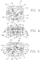
- the manifold has a body of the type of a solid block 120 made - in the embodiment shown - from stainless steel, it being understood that the choice of material is optional and depends on a particular application.
- the block has the shape of a rectangular prism and includes opposed top and bottom walls or first and second face sections 121 , 122 , a first side wall 123 , a second side wall 124 a front wall 125 and a rear wall 126 .
- the walls 123-126 are also referred to as "peripheral walls" as they enclose the periphery of the block 120 and are generally referred to as "a peripheral section.”
- Machined in the second face section 122 is a process fluid first inlet port 127 and a process fluid second inlet port 128 .
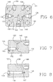
- the first inlet 127 communicates, via an upwardly and inwardly inclined first process passage 129 (Fig. 10) with a short horizontal branch 130 which defines a coaxial, inwards directed extension of a first block valve chamber 131 co-axial with a threaded first block valve opening 132 .
- the threaded opening 132 in effect forms a threaded outer portion of a block valve mounting bore comprised of the valve chamber 131 and the opening 132.
- Each valve chamber of the block defines a valve seat as will be described.
- the second inlet port 128 likewise communicates, via an upwardly and inwardly inclined second process passage 133 with a short horizontal branch 134 which defines a coaxial, inwards directed extension of a valve chamber 135 co-axial with a second block valve bore opening 136 .
- transition between the horizontal branch 130 at its inlet into the valve chamber 131 defines a valve seat co-operating with a valve member (not shown) for selectively blocking the entrance of pressurized process fluid into the valve chamber 131.
- transition between the branch 134 at its inlet into the valve chamber 135 defines a valve seat co-operating with a valve member (not shown) for selectively blocking the entrance of second pressurized process fluid into the valve chamber 135.
- the valve chamber 131 permanently communicates through a short first radial conduit 137 with a first instrument cavity 138 .
- the valve chamber 135 communicates via a short second radial conduit 139 with a second instrument cavity 140 .
- the cavity 138 is also in permanent communication with an inlet of an oblique conduit 141 which slopes in the direction from the top wall toward the bottom wall 122 and obliquely toward the second side wall 124, as best seen from Fig. 10.
- the outlet of the conduit 141 in turn, permanently communicates with a coaxial extension conduit 142 of the equalizer valve chamber 143 which, in turn, is coaxial with the threaded outer part 144 of the equalizer valve bore.
- the cavity 140 permanently communicates, through a vertical conduit 150 and an oblique conduit 145 , with the equalizer valve chamber 143.
- the general structure of the equalizer valve chamber 143 is similar to what has been described above. That is to say, the transition between the valve chamber 143 and the extension conduit 142 defines a valve seat for a valve member of a valve (not shown) normally threadably secured at the bore 144. It will be thus appreciated that with the equalizer valve open, the valve chamber 143 Fig. 6 and the extension conduit 142, and thus the two cavities 138, 140, are in a fluid communication to equalize the pressure in the cavities 138, 140.
- the cavity 138 further communicates, through an oblique conduit 146 which slopes from the top wall 121 to the bottom wall 122 and obliquely in the direction toward the rear wall 126 (Fig. 8), with an extension conduit 147 coaxial with a cylindric first vent valve chamber 148 which, in turn, is coaxial with a threaded valve bore 149 of a first vent valve.
- the conduit 150 connects the cavity 140 with the oblique conduit 145 and thus with the equalizer valve chamber 143.
- Fig. 7 shows that the lower portion of the vertical conduit 150 also connects the cavity 140 with a short extension conduit 151 forming a coaxial extension of a cylindric second vent valve chamber 152 which, in turn, is coaxial with a threaded part 153 of the valve mounting bore 153-152 of a second vent valve.
- vent valve chambers 148 and 152 and their extension conduits 147, 151 are arranged similar to the remaining valve chambers in that there is a valve seat at the inlet of each extension conduit 147, 151 into its associated valve chamber 148, 152.
- the seat is compatible with a closing member the structure of which will be described later.
- the inlet port of the conduit 154 is located in the side wall of the valve chamber 148, near the valve seat of the chamber 148.
- the downstream end of the transverse conduit 154 is in a permanent communication with a first vent outlet 155 (Fig. 11).
- the end of the shorter, second vent valve chamber 152 near its valve seat is similarly in a permanent communication with an inlet port (Fig. 9) of a second transverse conduit 156 and through it with a second vent outlet 157 .
- vent outlets 155, 157 are adapted to become connected to a suitable discharge conduits exterior to the body of the manifold and not forming a part of the invention.
- FIGs. 3, 5 and 6 In particular, apart from the relatively small thickness as measured between the upper and lower faces 121, 122, those figures show that there are four mounting holes 160 - 163 disposed about the periphery of the block 120.
- the axes of the holes 160 - 163 are perpendicular to the first face section 121.
- the axes of the holes 160 - 163 coincide with sides of a reference prism.
- the reference prism is a four-sided prism where the axes actually define each a joinder or corner between two adjacent sides.
- the number of the mounting holes is optional and is usually given by the disposition of mounting holes on a flange of a pressure transmitter or the like instrument to be used with the block 120. However, even if the number of the mounting holes is more than as shown, the arrangement is such that at least some of the axes of the mounting holes define corners of the reference prism.
- Both embodiments of the block described show a block for a five valve manifold. There are provisions made for mounting two block valves, one equalizer valve and two vent valves. Those skilled in the art will readily appreciate, however, that the features of the present invention can be applied in a three valve embodiment which typically has only two block valves and an equalizer valve.
- valve mounting openings namely the threaded bores 132 and 136 for two block valves for selectively blocking the passage of the process fluid and one equalizing valve mounting bore 144.
- valve chambers 131, 135 and the equalizer valve chamber 143 are all disposed with their inner ends (where the respective valve seats are located) located inside the imaginary prismatic surface.
- the remaining two valve chambers 148, 152 meet the same criteria as the "at least three" chambers 131, 135, 143 with respect to their location relative to the mounting bores 160-163.
- valve chambers 148, 1 52 and mounting bores are of a reduced diameter compared with chambers 131, 135, 143 but are relatively long to accommodate the type of a valve, where the valve seal is located on the valve stem and engages not the bonnet of the valve, but the interior of the valve chamber itself.
- This allows the use of an axially reduced length of the bonnet which, combined with a hexagonal head at the outer end of the valve stem, provides space saving feature whereby two valves can be located one to each side of another valve, in the exemplary embodiment, to each side of an equalizer valve.
- valves in which the seal is inside the valve chamber and the stem has a hexagonal head for engagement by a wrench or the like, be vent valves.
- the hexagonal heads provide an additional safety feature as with the distinct appearance they virtually eliminate the possibility of inadvertent opening of the two valves instead of one of the remaining three valves.
- vent valve chambers 148, 152 (and also 248, 253) having a specifically designed length which depends upon the location of the vent valve ports 155, 157 relative to the process inlet ports 127, 128 (and also 255 and 255 vis-a-vis 227, 228 as described hereafter with reference to Figs/ 12, 13.
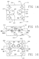
- Figs. 12 - 20 show the second embodiment of the manifold block according to the invention.
- the second embodiment includes features similar to those described with reference to Figs. 1 - 11, as witnessed, for instance, by the comments in the preceding paragraph.
- a solid, preferably, but not exclusively, stainless steel rectangular prism shaped block 220 As in the first embodiment, there is provided a solid, preferably, but not exclusively, stainless steel rectangular prism shaped block 220 .
- the block has top and bottom wall 221 , 222 , a first side wall 223 , a second side wall 224 a front wall 225 and a rear wall 226 .
- Fig. 16 shows first and second inlet ports 227 , 228 machined'in the bottom wall 222, for the process fluid.
- the inlet 227 communicates, via an upwardly and inwardly inclined first passage 229 with an extension 230 of a first block valve chamber 231 co-axial with a threaded first block valve bore 232 .
- the valve chamber 231 in turn, communicates via a short connecting conduit 233 with a first instrument cavity 234 .
- the second inlet 228 communicates in the same fashion, via second passage 235 , extension 236 and valve chamber 237 , coaxial with threaded bore 238 of the second block valve, and then via a short, vertical connecting conduit 239 with the second instrument cavity 240 .
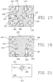
- the first instrument cavity 234 further communicates via a first short, vertical equalizer channel 241 with a horizontal-oblique channel 242 (Fig. 17) the discharge end of which connects with an equalizer valve chamber 243 .
- the second instrument cavity 240 communicates via a downwardly and inwardly sloping channel 244 the outlet of which merges with an inward end of an equalizer valve extension channel 245 (Figs. 17, 20) coaxial with the equalizer valve chamber 243.
- Each of the circular cavities 234, 240 is connected to the respective vent conduit.
- the cavity 234 connects via a vertical conduit 246 (Fig. 14) with a horizontal extension line 247 (Figs. 18, 19) coaxial and in communication with a first vent valve chamber 248 which, in turn, connects through a short vertical line 249 with a threaded vent discharge port 250 .
- the cavity 240 connects via a conduit 251 (Figs. 14, 17), a horizontal extension 252 coaxial with second vent valve chamber 253, the chamber 253 and a short vertical line 254 (Figs. 18, 19) with a threaded vent port 255.
- vent valve chambers 248, 253 are the same, but is greater than that of any of the remaining valve chambers 232, 237 and 243. This is to facilitate the orientation of the passageway sections 249, 254 which can be machined perpendicular to the second face 222 and straight into the vent discharge ports 250, 255 (Fig. 19).
- the threaded bores 256, 257 serve the purpose of securing the block 220 to a suitable support bracket or the like (not shown) and the four mounting holes 258 - 261 serve the purpose of accommodating bolts which hold a pressure transmitter in sealing engagement with the top surface 221 and thus with the cavities 234, 240.
- valve chambers 248, 253 of the vent valve mounting bores are of an even length. This feature accommodates the second preferred embodiment where the pairs of process fluid inlet ports 227, 228 and of the vent outlets 250, 255 are each on a separate reference line parallel with the other reference line, as opposed to the crossing arrangement of the reference lines in the first embodiment.
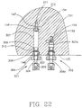
- Fig. 22 the enlarged representation generally corresponds to a partial cross section view on line XXII - XXII of Fig. 4.
- a pair of vent valves 301 , 302 installed in the first embodiment of the manifold block of the invention.
- the long vent valve chamber 148, and the associated coaxial threaded bore 149 and the transverse conduit 154 and the extension conduit 147 are as shown in Fig. 5.
- Threaded in the thread of the first vent valve bore 149 is a bonnet 303 having a wrench compatible outer hexagonal portion 304 .
- the bonnet 303 has a coaxial threaded bore 305 which is threadably engaged by a threaded portion of a vent valve stem 306 .
- the inner part of the stem 306, marked with reference number 307 is freely movable within the valve chamber 148.
- the end of the stem 307 carries a hemispherical tip 311 compatible with a valve seat 312.
- the tip 311 co-operates with the valve seat 312 to selectively block or open the passage of fluid from extension conduit 147 to the transverse conduit 154 and from there to the first vent outlet 155.
- the opposite, outer end of the stem 307 has fixedly secured to it a hexagonal head compatible with a suitable wrench. Accordingly the vent valve can only be open or closed by using a suitable tool.
- the valve mounted in the second vent valve mounting bore comprised (Fig. 7) of the threaded second vent valve bore 153 and the coaxial second vent valve chamber 152 communicating with the short extension conduit 151 and with the transverse conduit 156 (Fig. 11) which terminates at the second vent outlet 157.
- the overall arrangement of the second vent valve 302 is the same as that of the first vent valve described above except for the length of the inner part 307a of the valve stem 306a. Therefore, the parts of the second vent valve 302 and the associated second valve mounting bore are not described in detail.
- Fig. 22 shows the valves 301, 302 in an open state.
- the stem 306 can be turned to cause, an axial displacement of the stem 306 toward the seat 312 until the tip 311 sealingly engages the seat 312 to interrupt the flow of the fluid from extension line 147 to the transverse conduit 154.
- the manifold block is the same as that of Fig. 23, as indicated by reference number 125 designating the front wall of the block.
- the equalizer valve mounting bore comprises the valve chamber 143 (Fig. 6) and a threaded bore 144 at the front wall 125.
- the valve chamber 143 communicates, via an opening at the valve seat 320 with the extension conduit 142 and, via an opening in the side wall of the valve chamber 143, with the oblique conduit 145.
- the threaded bore 144 threadably receives a bonnet 321 of an equalizer valve referred to with reference number 322 .
- the equalizer valve 322 and thus the equalizer valve mounting bore 144, 143 are of the type typically used in valve manifold of this type. That is to say, the valve 322 is of the type wherein a valve stem 323 is threadably received in the bonnet 321.
- the bonnet has an outer thread 325 mounted in the threaded bore 144, as is well known in the art.
- the bonnet defines a packing chamber which receives a packing 326 held in place and compressed by a packing gland 327 threaded in the outer end of the packing chamber and locked in its position by a locking nut 328 .
- the inside and axially outer portion of the gland 327 is threaded by a thread compatible with that on the outside of the stem 323.
- a dust cap 329 protects the threaded connection between the stem 323 and the gland 327.
- the inner end of the stem 323 is provided with a hemispherical closing member 330 compatible with the seat 320 so that the operation of the valve 322 by the handle 331 results in selective closing or opening of the fluid flow from the extension conduit 142, through the valve chamber 143 and into the oblique conduit.
- the valve 322 is one of many commercially available valves of the type with the packing inside the bonnet. It can be readily appreciated that the valve 322 requires substantially more space at the exterior of the manifold (i.e. at the vicinity of the front wall 125) both as to the overall maximum length as a distance from the wall 125, and as regards the overall diameter.
- the vent valve 301 or 302 requires a much shorter outer length and a smaller diameter, not to mention that the selectively designed length of the valve chamber 148 or 152 can be utilized in simplifying the structure of the conduits of the manifold by bringing the respective valve seat and the outlet port to a position where the connecting conduits do not require to be at a complex angle of a double oblique inclination relative to the surface of the block.
Landscapes
- Valve Housings (AREA)
Claims (15)
- Collecteur à soupape à utiliser avec un appareil détectant la pression, comprenant en combinaison:caractérisé en ce que(a) un corps solidaire (120, 220) englobant une première section frontale (121, 221), une deuxième section frontale (122, 222) généralement parallèle à la première section frontale (121, 221) et une section périphérique polygonale (123-126; 223-226) de préférence en forme de quadrilatère s'étendant entre les première et deuxième sections frontales;(b) un moyen d'orifice d'entrée de fluide de traitement (127, 128; 227, 228) dans ladite deuxième section frontale (122, 222) et un moyen d'orifice de sortie de fluide de traitement (138, 140; 234, 240) dans ladite première section frontale (121, 221), ledit moyen d'orifice de sortie de fluide de traitement (138, 140; 234, 240) épousant la forme des orifices d'entrée d'un appareil associé détectant la pression;(c) un système de passages comprenant plusieurs passages établissant une communication de fluide entre lesdits moyens d'orifices d'entrée et de sortie l'un par rapport à l'autre;(d) plusieurs trous de montage d'appareil (160-163; 258-261) prévus dans ladite première section frontale (121, 221) et disposés autour de la périphérie de la première section frontale (121, 221) de préférence à proximité du coin de ladite section périphérique, pour que viennent s'y loger des boulons fixant en entraínement l'appareil détectant la pression à ladite première section frontale (121, 221);(e) lesdits trous de montage d'appareil (160-163; 258-261) possédant des axes généralement perpendiculaires à ladite première section frontale (121, 221), lesdits axes définissant les côtés d'un prisme de référence dont les extrémités sont coplanaires avec lesdites première et deuxième sections frontales, au moins un certain nombre desdits axes coïncidant avec les coins dudit prisme de référence;(f) plusieurs alésages de montage de soupapes (132, 136, 144, 149, 153; 232, 238, 243, 248, 263), chaque alésage s'étendant depuis un endroit sur ladite section périphérique (123-126; 223-226) jusqu'à l'intérieur du corps, chaque alésage de montage de soupape englobant une portion terminale externe filetée à ladite section périphérique (123-126; 223-226) et une chambre de soupape coaxiale généralement cylindrique (131, 135, 143, 148, 152; 231, 237, 243, 248, 253) définissant une portion terminale interne de l'alésage, formant une partie dudit système de passage;(g) chaque chambre de soupape englobant un siège de soupape coïncidant avec une sortie d'une section amont d'un passage respectif, menant à la chambre de soupape respective;(h) chacune desdites chambres de soupapes communiquant en outre via un orifice prévu dans une paroi latérale de la première citée, avec une section aval du passage respectif;
le siège de soupape de chacune desdites chambres de soupapes (131, 135, 143, 148, 152, 231, 237, 243, 248, 253) est situé à l'intérieur d'un espace délimité par ledit prisme de référence. - Collecteur à soupape selon la revendication 1, dans lequel(i) le collecteur comprend une paire de moyens d'orifices de sortie de désaération (155, 157; 250, 255),(ii) lesdits deux moyens d'orifices de sortie de désaération sont disposés dans ladite deuxième section frontale (122, 222);(iii) chaque moyen d'orifice de sortie de désaération (155, 157; 250, 255) communique par fluide avec un orifice de communication prévu dans la paroi latérale de sa chambre de soupape associée (148, 152; 248, 253) à proximité de son siège de soupape de désaération;(iv) lesdites chambres de soupapes de désaération (148, 152; 248, 253) sont toutes deux prévues dans la même paroi périphérique, définissant chacune une partie d'un alésage faisant partie d'une paire d'alésages de montage de soupapes de désaération (149, 153, 248, 253),(v) la longueur de l'une quelconque desdites chambres de soupapes de désaération est supérieure à celle de l'une quelconque des chambres de soupapes restantes (131, 135, 143, 231, 237, 243).
- Collecteur selon la revendication 1, englobant deux, trois, quatre ou cinq desdits alésages de montage de soupapes (132, 136, 144, 149, 153; 232, 238, 243, 248, 253) et comprenant des moyens d'orifices de sortie de désaération (155, 157; 250, 255), dans lequel les moyens d'orifice de sortie de désaération (155, 157; 250, 255) sont disposés dans ladite deuxième section frontale (122, 222).
- Collecteur selon la revendication 3, dans lequel le moyen d'orifice d'entrée de fluide de traitement représente une paire d'orifices d'entrée (127, 128) et les moyens d'orifices de sortie de désaération (155, 157) représentent une paire d'orifices de sortie de désaération, et dans lequel les centres des orifices d'entrée (127, 128) sont disposés sur une première ligne de référence coïncidant avec ladite deuxième section frontale (122), les centres des orifices de sortie de désaération (155, 157) étant disposés sur une seconde ligne de référence coïncidant avec ladite deuxième section frontale (122) et coupant la première ligne de référence en formant en général un angle droit, le point d'intersection des lignes de référence étant disposé généralement au centre de ladite deuxième section frontale (122).
- Collecteur selon la revendication 3, dans lequel les moyens d'orifices d'entrée de fluide de traitement représentent une paire d'orifices d'entrée (227, 228) et les moyens d'orifices de sortie de désaération représentent une paire d'orifices de sortie de désaération (250, 255), et dans lequel les centres des orifices d'entrée (227, 228) sont disposés sur une première ligne de référence coïncidant avec ladite deuxième section frontale (222) et les centres des orifices de sortie de désaération (250, 255) sont disposés sur une seconde ligne de référence coïncidant avec ladite deuxième section frontale (222) et s'étendent généralement parallèlement à ladite première ligne de référence.
- Collecteur à soupape selon l'une quelconque des revendications 2, 3, 4 ou 5, dans lequel la section périphérique (123-126; 223-226) comprend plusieurs parois périphériques généralement planes (123-126; 223-226), une paroi (125, 225) desdites parois périphériques étant munie d'une paire d'alésages de montage de soupapes de désaération parallèles (149, 153; 248, 253); chaque chambre de soupape de désaération (148, 152; 248, 253) des alésages de montage de soupapes de désaération communiquant par fluide, via un orifice de communication, avec une extrémité d'un conduit de désaération (154, 156; 249, 254), l'autre extrémité du conduit de désaération communiquant par fluide avec une sortie de désaération respective (155, 157; 250, 255), et dans lequel les axes des chambres de soupapes de désaération (148, 152; 248, 253) sont équidistants par rapport à ladite première section frontale (121, 221) et dans lequel l'orifice de communication respectif est situé à proximité du siège de soupape de la chambre de soupape de désaération respective (148, 152; 248, 253).
- Collecteur selon la revendication 6 lorsqu'elle dépend de la revendication 4, dans lequel les chambres de soupapes de désaération (148, 152) sont de longueur différente, les orifices de communication étant ainsi respectivement disposés à une distance différente par rapport à ladite paroi (125) desdites parois périphériques.
- Collecteur selon la revendication 2 ou 7, dans lequel chaque alésage de montage de soupape de désaération (149, 153) de ladite paire est muni d'un assemblage de soupape englobant une tige de soupape (306, 306A) vissée dans un chapeau (303) épousant la forme d'une portion externe filetée (149, 153), et possédant un élément de fermeture de soupape (311) à une extrémité libre de la tige (306), destiné à entrer en contact avec le siège de soupape respectif, ainsi qu'un joint étanche (310) destiné à entrer en contact d'étanchéité avec ladite tige (306, 306A), et dans lequel ledit assemblage de soupapes est du type dans lequel le joint étanche (310) est conçu pour entrer en outre en contact d'étanchéité avec la chambre de soupape cylindrique respective, ledit joint étanche (310) étant disposé à un endroit de la tige (306, 306A) situé entre l'élément de fermeture et le chapeau (303), le chapeau étant dépourvu d'une mise en contact d'étanchéité avec la tige et possédant par conséquent un diamètre global réduit.
- Collecteur selon l'une quelconque des revendications 6, 7 ou 8, dans lequel on prévoit de préférence un troisième alésage de montage de soupape de compensation (143, 243) dans ladite paroi (125, 225) desdites parois périphériques, ledit troisième alésage de montage de soupape (143, 243):(a) étant généralement parallèle à ladite paire d'alésages de montage de soupapes de désaération (149, 153; 248, 253),(b) étant disposé entre ladite paire desdits alésages de montage de soupapes de désaération et à un endroit moins éloigné de la section (121, 221) desdites sections frontales;(c) possédant un siège de soupape disposé plus près de ladite paroi (125, 225) des parois périphériques que le siège de soupape de l'une quelconque desdites paires d'alésages de montage de soupapes de désaération (149, 153; 248, 253).
- Collecteur selon la revendication 9, comprenant deux alésages de montage de soupapes de séparation (132, 136; 232, 238) prévus respectivement dans respectivement deux parois périphériques supplémentaires généralement planes (123, 124; 223, 224) du corps (120, 220); dans lequel lesdites parois périphériques supplémentaires (123, 124; 223, 224) représentent deux parois périphériques opposées parallèles distinctes de ladite paroi (125, 225) desdites parois périphériques.
- Collecteur à soupape selon l'une quelconque des revendications précédentes, dans lequel lesdits passages comprennent plusieurs sections de passages rectilignes communiquant l'une avec l'autre, avec lesdits moyens d'orifices et avec lesdites chambres de soupapes, et dans lequel lesdites sections de passages sont disposées et arrangées de telle sorte que chaque section de passage est parallèle au moins avec, soit lesdites sections frontales (121, 122; 221, 222), soit lesdites parois périphériques (123, 124, 223, 224), soit lesdites parois frontales et dorsales (125, 126; 225, 226), ce qui facilite l'usinage desdites sections de passages.
- Collecteur à soupape selon l'une quelconque des revendications précédentes, dans lequel(a) les axes de trois desdits alésages de montage de soupapes (132, 136, 144; 232, 238, 243) sont disposés sur un premier plan de référence parallèle auxdites sections frontales (121, 122; 221, 222); et(b) les axes de deux desdits alésages de montage de soupapes (149, 153; 248, 253) sont disposés sur un second plan de référence parallèle auxdites sections frontales (121, 122; 221, 222) tout en étant espacés dudit premier plan de référence.
- Collecteur à soupape selon la revendication 12, dans lequel lesdits deux alésages (149, 153; 248, 253) desdits alésages de montage de soupapes représentent des alésages de montage de soupapes de désaération.
- Collecteur selon la revendication 8, dans lequel une extrémité externe de la tige de soupape de désaération (306, 306A) dudit assemblage de soupapes de désaération, éloignée de l'élément de fermeture de soupape (330), est configurée à des fins de mise en contact avec une clé ou avec un outil complémentaire analogue aisément amovible induisant un couple.
- Collecteur selon l'une quelconque des revendications précédentes, dans lequel les centres desdits moyens d'orifices d'entrée de fluide de traitement (127, 128; 227, 228) et desdits moyens d'orifices de sortie de fluide de traitement (138, 140; 234, 240) sont situés dans un espace délimité par ledit prisme de référence.
Applications Claiming Priority (3)
| Application Number | Priority Date | Filing Date | Title |
|---|---|---|---|
| US869295P | 1995-12-15 | 1995-12-15 | |
| US8692P | 1995-12-15 | ||
| PCT/CA1996/000842 WO1997022867A1 (fr) | 1995-12-15 | 1996-12-16 | Collecteur a soupapes multiples destine a un dispositif de traitement de mesures de pression |
Publications (2)
| Publication Number | Publication Date |
|---|---|
| EP0866959A1 EP0866959A1 (fr) | 1998-09-30 |
| EP0866959B1 true EP0866959B1 (fr) | 2000-01-19 |
Family
ID=21733126
Family Applications (1)
| Application Number | Title | Priority Date | Filing Date |
|---|---|---|---|
| EP96940969A Expired - Lifetime EP0866959B1 (fr) | 1995-12-15 | 1996-12-16 | Collecteur a soupapes multiples destine a un dispositif de traitement de mesures de pression |
Country Status (4)
| Country | Link |
|---|---|
| EP (1) | EP0866959B1 (fr) |
| AT (1) | ATE189046T1 (fr) |
| CA (1) | CA2239492C (fr) |
| DE (1) | DE69606323T2 (fr) |
Cited By (1)
| Publication number | Priority date | Publication date | Assignee | Title |
|---|---|---|---|---|
| US20230296462A1 (en) * | 2022-03-16 | 2023-09-21 | R.J. Machine Company, Inc. | Manifold for use with a pressure transmitter |
-
1996
- 1996-12-16 EP EP96940969A patent/EP0866959B1/fr not_active Expired - Lifetime
- 1996-12-16 CA CA002239492A patent/CA2239492C/fr not_active Expired - Fee Related
- 1996-12-16 AT AT96940969T patent/ATE189046T1/de not_active IP Right Cessation
- 1996-12-16 DE DE69606323T patent/DE69606323T2/de not_active Expired - Lifetime
Cited By (2)
| Publication number | Priority date | Publication date | Assignee | Title |
|---|---|---|---|---|
| US20230296462A1 (en) * | 2022-03-16 | 2023-09-21 | R.J. Machine Company, Inc. | Manifold for use with a pressure transmitter |
| US12416539B2 (en) * | 2022-03-16 | 2025-09-16 | R.J. Machine Company, Inc. | Manifold with inter-opening features for use with a pressure transmitter |
Also Published As
| Publication number | Publication date |
|---|---|
| CA2239492C (fr) | 2006-11-14 |
| DE69606323D1 (de) | 2000-02-24 |
| CA2239492A1 (fr) | 1997-06-26 |
| DE69606323T2 (de) | 2000-06-08 |
| EP0866959A1 (fr) | 1998-09-30 |
| ATE189046T1 (de) | 2000-02-15 |
Similar Documents
| Publication | Publication Date | Title |
|---|---|---|
| AU714184B2 (en) | Multiple valve manifold for use with a pressure processing apparatus | |
| EP0737285B1 (fr) | Collecteur a multiples valves destine a etre utilise avec un appareil de mesure de pression | |
| US5988203A (en) | Two-piece manifold | |
| US6389904B1 (en) | Manifold for use with a pressure transmitter | |
| US4582089A (en) | Valve manifold having a removable flange | |
| US5494071A (en) | Mounting system for pressure transmitters | |
| US3550621A (en) | Fluid distributing manifold for directional control valve | |
| CA2236984A1 (fr) | Raccords pour appareils de commande a fluide | |
| EP1123476B1 (fr) | Collecteur utilisable avec deux capteurs de pression | |
| US5832956A (en) | Three valve controlled vent manifold | |
| EP1015861B1 (fr) | Collecteur en deux pieces | |
| EP0866959B1 (fr) | Collecteur a soupapes multiples destine a un dispositif de traitement de mesures de pression | |
| EP1123493B1 (fr) | Collecteurs a vannes pour instruments utilisables avec des transmetteurs de pression | |
| JPH0437317B2 (fr) | ||
| US3610283A (en) | Four-way hydraulic valve | |
| MXPA98004668A (en) | Distributor of multiple valves for use with a processing device of pres | |
| US5083586A (en) | Mounting arrangement for connecting a fluid pressure valve to a pipe bracket by a hollow adapter member | |
| JPH0220877B2 (fr) | ||
| US6182701B1 (en) | Swivel-type static pressure bar adapter | |
| JPS6131247Y2 (fr) | ||
| MXPA99006393A (es) | Cabezal de distribucion de dos piezas | |
| JPH0643442U (ja) | マニホールドバルブ |
Legal Events
| Date | Code | Title | Description |
|---|---|---|---|
| PUAI | Public reference made under article 153(3) epc to a published international application that has entered the european phase |
Free format text: ORIGINAL CODE: 0009012 |
|
| 17P | Request for examination filed |
Effective date: 19980612 |
|
| AK | Designated contracting states |
Kind code of ref document: A1 Designated state(s): AT BE CH DE DK ES FI FR GB GR IE IT LI LU MC NL PT SE |
|
| GRAG | Despatch of communication of intention to grant |
Free format text: ORIGINAL CODE: EPIDOS AGRA |
|
| 17Q | First examination report despatched |
Effective date: 19990323 |
|
| GRAG | Despatch of communication of intention to grant |
Free format text: ORIGINAL CODE: EPIDOS AGRA |
|
| GRAH | Despatch of communication of intention to grant a patent |
Free format text: ORIGINAL CODE: EPIDOS IGRA |
|
| GRAH | Despatch of communication of intention to grant a patent |
Free format text: ORIGINAL CODE: EPIDOS IGRA |
|
| GRAA | (expected) grant |
Free format text: ORIGINAL CODE: 0009210 |
|
| AK | Designated contracting states |
Kind code of ref document: B1 Designated state(s): AT BE CH DE DK ES FI FR GB GR IE IT LI LU MC NL PT SE |
|
| PG25 | Lapsed in a contracting state [announced via postgrant information from national office to epo] |
Ref country code: SE Free format text: THE PATENT HAS BEEN ANNULLED BY A DECISION OF A NATIONAL AUTHORITY Effective date: 20000119 Ref country code: LI Free format text: LAPSE BECAUSE OF FAILURE TO SUBMIT A TRANSLATION OF THE DESCRIPTION OR TO PAY THE FEE WITHIN THE PRESCRIBED TIME-LIMIT Effective date: 20000119 Ref country code: IT Free format text: LAPSE BECAUSE OF FAILURE TO SUBMIT A TRANSLATION OF THE DESCRIPTION OR TO PAY THE FEE WITHIN THE PRESCRIBED TIME-LIMIT;WARNING: LAPSES OF ITALIAN PATENTS WITH EFFECTIVE DATE BEFORE 2007 MAY HAVE OCCURRED AT ANY TIME BEFORE 2007. THE CORRECT EFFECTIVE DATE MAY BE DIFFERENT FROM THE ONE RECORDED. Effective date: 20000119 Ref country code: GR Free format text: LAPSE BECAUSE OF NON-PAYMENT OF DUE FEES Effective date: 20000119 Ref country code: FR Free format text: LAPSE BECAUSE OF FAILURE TO SUBMIT A TRANSLATION OF THE DESCRIPTION OR TO PAY THE FEE WITHIN THE PRESCRIBED TIME-LIMIT Effective date: 20000119 Ref country code: FI Free format text: LAPSE BECAUSE OF FAILURE TO SUBMIT A TRANSLATION OF THE DESCRIPTION OR TO PAY THE FEE WITHIN THE PRESCRIBED TIME-LIMIT Effective date: 20000119 Ref country code: ES Free format text: THE PATENT HAS BEEN ANNULLED BY A DECISION OF A NATIONAL AUTHORITY Effective date: 20000119 Ref country code: CH Free format text: LAPSE BECAUSE OF FAILURE TO SUBMIT A TRANSLATION OF THE DESCRIPTION OR TO PAY THE FEE WITHIN THE PRESCRIBED TIME-LIMIT Effective date: 20000119 Ref country code: BE Free format text: LAPSE BECAUSE OF FAILURE TO SUBMIT A TRANSLATION OF THE DESCRIPTION OR TO PAY THE FEE WITHIN THE PRESCRIBED TIME-LIMIT Effective date: 20000119 Ref country code: AT Free format text: LAPSE BECAUSE OF FAILURE TO SUBMIT A TRANSLATION OF THE DESCRIPTION OR TO PAY THE FEE WITHIN THE PRESCRIBED TIME-LIMIT Effective date: 20000119 |
|
| REF | Corresponds to: |
Ref document number: 189046 Country of ref document: AT Date of ref document: 20000215 Kind code of ref document: T |
|
| REG | Reference to a national code |
Ref country code: CH Ref legal event code: EP |
|
| REF | Corresponds to: |
Ref document number: 69606323 Country of ref document: DE Date of ref document: 20000224 |
|
| REG | Reference to a national code |
Ref country code: IE Ref legal event code: FG4D |
|
| PG25 | Lapsed in a contracting state [announced via postgrant information from national office to epo] |
Ref country code: PT Free format text: LAPSE BECAUSE OF FAILURE TO SUBMIT A TRANSLATION OF THE DESCRIPTION OR TO PAY THE FEE WITHIN THE PRESCRIBED TIME-LIMIT Effective date: 20000419 Ref country code: DK Free format text: LAPSE BECAUSE OF FAILURE TO SUBMIT A TRANSLATION OF THE DESCRIPTION OR TO PAY THE FEE WITHIN THE PRESCRIBED TIME-LIMIT Effective date: 20000419 |
|
| EN | Fr: translation not filed | ||
| REG | Reference to a national code |
Ref country code: CH Ref legal event code: PL |
|
| PLBE | No opposition filed within time limit |
Free format text: ORIGINAL CODE: 0009261 |
|
| STAA | Information on the status of an ep patent application or granted ep patent |
Free format text: STATUS: NO OPPOSITION FILED WITHIN TIME LIMIT |
|
| PG25 | Lapsed in a contracting state [announced via postgrant information from national office to epo] |
Ref country code: LU Free format text: LAPSE BECAUSE OF NON-PAYMENT OF DUE FEES Effective date: 20001216 |
|
| PG25 | Lapsed in a contracting state [announced via postgrant information from national office to epo] |
Ref country code: IE Free format text: LAPSE BECAUSE OF NON-PAYMENT OF DUE FEES Effective date: 20001218 |
|
| PG25 | Lapsed in a contracting state [announced via postgrant information from national office to epo] |
Ref country code: MC Free format text: THE PATENT HAS BEEN ANNULLED BY A DECISION OF A NATIONAL AUTHORITY Effective date: 20001231 |
|
| 26N | No opposition filed | ||
| REG | Reference to a national code |
Ref country code: IE Ref legal event code: MM4A |
|
| REG | Reference to a national code |
Ref country code: GB Ref legal event code: IF02 |
|
| REG | Reference to a national code |
Ref country code: DE Ref legal event code: R082 Ref document number: 69606323 Country of ref document: DE Representative=s name: MEHLER ACHLER PATENTANWAELTE PARTNERSCHAFT MBB, DE Ref country code: DE Ref legal event code: R082 Ref document number: 69606323 Country of ref document: DE Representative=s name: MEHLER ACHLER PATENTANWAELTE, DE |
|
| PGFP | Annual fee paid to national office [announced via postgrant information from national office to epo] |
Ref country code: GB Payment date: 20141229 Year of fee payment: 19 |
|
| PGFP | Annual fee paid to national office [announced via postgrant information from national office to epo] |
Ref country code: NL Payment date: 20141226 Year of fee payment: 19 |
|
| PGFP | Annual fee paid to national office [announced via postgrant information from national office to epo] |
Ref country code: DE Payment date: 20141230 Year of fee payment: 19 |
|
| REG | Reference to a national code |
Ref country code: DE Ref legal event code: R119 Ref document number: 69606323 Country of ref document: DE |
|
| GBPC | Gb: european patent ceased through non-payment of renewal fee |
Effective date: 20151216 |
|
| REG | Reference to a national code |
Ref country code: NL Ref legal event code: MM Effective date: 20160101 |
|
| PG25 | Lapsed in a contracting state [announced via postgrant information from national office to epo] |
Ref country code: GB Free format text: LAPSE BECAUSE OF NON-PAYMENT OF DUE FEES Effective date: 20151216 Ref country code: NL Free format text: LAPSE BECAUSE OF NON-PAYMENT OF DUE FEES Effective date: 20160101 Ref country code: DE Free format text: LAPSE BECAUSE OF NON-PAYMENT OF DUE FEES Effective date: 20160701 |