EP0867134A2 - Nachttisch - Google Patents
Nachttisch Download PDFInfo
- Publication number
- EP0867134A2 EP0867134A2 EP98100425A EP98100425A EP0867134A2 EP 0867134 A2 EP0867134 A2 EP 0867134A2 EP 98100425 A EP98100425 A EP 98100425A EP 98100425 A EP98100425 A EP 98100425A EP 0867134 A2 EP0867134 A2 EP 0867134A2
- Authority
- EP
- European Patent Office
- Prior art keywords
- chassis
- bedside table
- table according
- bedside
- locking
- Prior art date
- Legal status (The legal status is an assumption and is not a legal conclusion. Google has not performed a legal analysis and makes no representation as to the accuracy of the status listed.)
- Granted
Links
- 239000002184 metal Substances 0.000 claims abstract description 3
- 238000004512 die casting Methods 0.000 claims abstract 3
- 238000004519 manufacturing process Methods 0.000 description 2
- 230000015572 biosynthetic process Effects 0.000 description 1
- 230000006835 compression Effects 0.000 description 1
- 238000007906 compression Methods 0.000 description 1
- 230000000881 depressing effect Effects 0.000 description 1
- 238000003780 insertion Methods 0.000 description 1
- 230000037431 insertion Effects 0.000 description 1
- 230000000474 nursing effect Effects 0.000 description 1
Images


Classifications
-
- A—HUMAN NECESSITIES
- A47—FURNITURE; DOMESTIC ARTICLES OR APPLIANCES; COFFEE MILLS; SPICE MILLS; SUCTION CLEANERS IN GENERAL
- A47B—TABLES; DESKS; OFFICE FURNITURE; CABINETS; DRAWERS; GENERAL DETAILS OF FURNITURE
- A47B49/00—Revolving cabinets or racks; Cabinets or racks with revolving parts
- A47B49/004—Cabinets with compartments provided with trays revolving on a vertical axis
-
- A—HUMAN NECESSITIES
- A47—FURNITURE; DOMESTIC ARTICLES OR APPLIANCES; COFFEE MILLS; SPICE MILLS; SUCTION CLEANERS IN GENERAL
- A47B—TABLES; DESKS; OFFICE FURNITURE; CABINETS; DRAWERS; GENERAL DETAILS OF FURNITURE
- A47B79/00—Bedside cabinets
-
- A—HUMAN NECESSITIES
- A47—FURNITURE; DOMESTIC ARTICLES OR APPLIANCES; COFFEE MILLS; SPICE MILLS; SUCTION CLEANERS IN GENERAL
- A47B—TABLES; DESKS; OFFICE FURNITURE; CABINETS; DRAWERS; GENERAL DETAILS OF FURNITURE
- A47B2200/00—General construction of tables or desks
- A47B2200/0035—Tables or desks with features relating to adjustability or folding
- A47B2200/004—Top adjustment
- A47B2200/0048—Concealable top fixed on a bedside table or similar
Definitions
- the present invention relates to a bedside table according to the preamble of Claim 1.
- Such bedside tables are preferably used as side tables for hospital or nursing beds Use.
- the drawer Since the alignment position of the bed table is predetermined and usually towards the foot section of the bed, the drawer must be used for the optional placement of the bedside table can be pulled out of the bed either on the right or left side, on both sides.
- the present invention is therefore based on the object of a bedside table Generic type to be designed so that in any desired position Use of the same page is possible.
- the drawer can be used in such a way designed bedside table that it can only be pulled out from one side, regardless of which side Bedside of the bedside table is placed.
- the invention provides both in terms of manufacture and usability represent a significant improvement over the prior art.
- the rotation the body is controlled by 180 °.
- a slide track can be installed either in the chassis or in the base of the body be provided of a link pin, either at the bottom of the body, at a scenery track provided in the chassis, or on the chassis, in a Bottom of the body recessed backdrop, is guided.
- the course of the slide is designed in such a way that a very tight turn past of the body on a holding part firmly connected to the chassis for the bed table is possible.
- This holding part can consist, for example, of an upright column, at the upper end of the bed table is pivotally attached.
- Another idea of the invention provides that the locking means by which the Body is fixed in a respective end position on the chassis, from the Top of the body can be operated via a linkage.
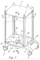
- a bedside table is shown, the chassis provided with rollers 3 2, a body part 1 and a bed table 10.
- the body part 1 is with a Base plate 13 (Fig. 2), a storage plate 7 and four vertical supports 9 provided that connect the bottom plate 13 and the storage plate 7 and which are each arranged in the four corners of the body part 1.
- the supports 9 are delimited on the top by round buttons 12, between which one Railing 8 is arranged in the form that one side is open.
- Fig. 2 it can be seen that the chassis 2, the bottom plate 13 adjacent, has a receptacle 22 in which an upright column 11 is positively positioned is attached to the bed table 10 from a non-use position, as in the Fig. 1 is shown, is pivoted into a position of use.
- a pivot pin 18 is attached, which engages in an elongated hole 19, the is provided on the underside of the base plate 13 and that in the direction of Recording 22 extends.
- the base plate 13 has a slide track 20, in which one with the chassis 2 connected link pin 21 is guided.
- the track 20 is designed in its course so that when rotating the body 1 is guided very close to the column 11. With this forced guidance the slot 19 on the pivot 18 is moved accordingly, the Correspondence between the two parts also represents a fixation.
- a locking pin 16 is provided as a locking means, which is part of a rocker 14 fastened on the underside of the base plate 13, which rests on tilting bearings 15 and on their opposite the locking pin 16 Side can be actuated by locking bars 23.
- the locking pin 16 engages in a locking opening 17 in the chassis 2 is provided.
- the rocker 14 By depressing the ball buttons 12, preferably against the force of one Compression spring, the rocker 14 is confirmed so that the locking pin 16 from the locking opening 17 is pulled. After rotating the body 1 by 180 °, it snaps under load the ball knobs 12 of the locking pin 16 in a further, opposite Locking opening 17, so that the body 1 is locked in this position.
Landscapes
- Drawers Of Furniture (AREA)
- Tables And Desks Characterized By Structural Shape (AREA)
- Combinations Of Kitchen Furniture (AREA)
Abstract
Description
- 1
- Korpus
- 2
- Fahrgestell
- 3
- Rolle
- 4
- Fächerteil
- 5
- Tür
- 6
- Schubkasten
- 7
- Ablageplatte
- 8
- Reling
- 9
- Stütze
- 10
- Bettisch
- 11
- Säule
- 12
- Kugelknopf
- 13
- Bodenplatte
- 14
- Wippe
- 15
- Kipplager
- 16
- Rastzapfen
- 17
- Rastöffnung
- 18
- Drehzapfen
- 19
- Langloch
- 20
- Kulissenbahn
- 21
- Kulissenzapfen
- 22
- Aufnahme
- 23
- Riegelstange
Claims (12)
- Nachttisch mit einem auf einem Fahrgestell (2) befestigten Korpus (1), in dem ein Schubkasten und/oder Fächer (6) angeordnet ist, und einem von einer Nichtgebrauchs- in eine Gebrauchsstellung schwenkbaren Bettisch (10), dadurch gekennzeichnet, daß der Korpus (1) drehbar zum Bettisch (10) am Fahrgestell (2) befestigt ist und daß Arretiermittel vorgesehen sind, durch die der Korpus (1) in einer jeweiligen Endstellung festgesetzt ist.
- Nachttisch nach Anspruch 1, dadurch gekennzeichnet, daß der Bettisch (10) an einer mit dem Fahrgestell (2) verbundenen Säule (11) befestigt ist.
- Nachttisch nach Anspruch 1, dadurch gekennzeichnet, daß der Korpus (1) in seiner Drehbewegung gegenüber dem Fahrgestell (2) zwangsgeführt ist.
- Nachttisch nach Anspruch 3, dadurch gekennzeichnet, daß eine Bodenplatte (13) des Korpus (1) oder das Fahrgestell (2) eine Kulissenbahn (20) aufweist, in der ein Kulissenzapfen (21), der fest mit dem Fahrgestell (2) oder der Bodenplatte (20) verbunden ist, geführt ist.
- Nachttisch nach Anspruch 1 oder 3, dadurch gekennzeichnet, daß an dem Fahrgestell (2) ein Drehzapfen (18) befestigt ist, der in einem in der Bodenplatte (13) vorgesehenen Langloch (19) geführt ist.
- Nachttisch nach Anspruch 1, dadurch gekennzeichnet, daß als Arretiermittel eine Wippe (14) vorgesehen ist, die einen Rastzapfen (16) aufweist, der in der jeweiligen Endstellung in eine Rastöffnung (17) einliegt.
- Nachttisch nach Anspruch 6, dadurch gekennzeichnet, daß die Wippe (14) durch Riegelstangen (23) betätigbar ist.
- Nachttisch nach Anspruch 6, dadurch gekennzeichnet, daß die Wippe (14) unterhalb der Bodenplatte (13) und die Rastöffnungen (17) im Fahrgestell (2) angeordnet sind.
- Nachttisch nach Anspruch 7, dadurch gekennzeichnet, daß die Riegelstangen (23) in Stützen (9) des Korpus (1) geführt sind und endseitig mittels jeweils eines Kugelknopfes (12) betätigbar sind.
- Nachttisch nach Anspruch 9, dadurch gekennzeichnet, daß die Riegelstangen (23) gegen einen Federdruck betätigbar sind.
- Nachttisch nach Anspruch 1, dadurch gekennzeichnet, daß das Fahrgestell (2) aus Druckguß besteht.
- Nachttisch nach Anspruch 11, dadurch gekennzeichnet, daß das Fahrgestell (2) aus Leichtmetall-Druckguß besteht.
Applications Claiming Priority (2)
| Application Number | Priority Date | Filing Date | Title |
|---|---|---|---|
| DE19712681 | 1997-03-26 | ||
| DE19712681A DE19712681C1 (de) | 1997-03-26 | 1997-03-26 | Nachttisch |
Publications (3)
| Publication Number | Publication Date |
|---|---|
| EP0867134A2 true EP0867134A2 (de) | 1998-09-30 |
| EP0867134A3 EP0867134A3 (de) | 1999-07-07 |
| EP0867134B1 EP0867134B1 (de) | 2002-07-03 |
Family
ID=7824675
Family Applications (1)
| Application Number | Title | Priority Date | Filing Date |
|---|---|---|---|
| EP98100425A Expired - Lifetime EP0867134B1 (de) | 1997-03-26 | 1998-01-13 | Nachttisch |
Country Status (3)
| Country | Link |
|---|---|
| EP (1) | EP0867134B1 (de) |
| AT (1) | ATE219900T1 (de) |
| DE (1) | DE19712681C1 (de) |
Cited By (4)
| Publication number | Priority date | Publication date | Assignee | Title |
|---|---|---|---|---|
| EP0934714A1 (de) * | 1998-02-06 | 1999-08-11 | Joh. Stiegelmeyer GmbH & Co. KG | Verfahrbarer Nachttisch |
| FR2847136A1 (fr) * | 2002-11-20 | 2004-05-21 | Hill Rom Sas | Meuble hospitalier a plateau basculant |
| ITPD20120334A1 (it) * | 2012-11-08 | 2014-05-09 | Malvestio Guido Ind Spa | Comodino bifronte con tavolino di servizio su ruote |
| WO2022036573A1 (zh) * | 2020-08-18 | 2022-02-24 | 南京溧水高新创业投资管理有限公司 | 一种多功能床头柜家具 |
Families Citing this family (5)
| Publication number | Priority date | Publication date | Assignee | Title |
|---|---|---|---|---|
| AU2002309987A1 (en) | 2001-05-25 | 2002-12-09 | Hill-Rom Services, Inc. | Modular patient room |
| US7073765B2 (en) | 2002-11-13 | 2006-07-11 | Hill-Rom Services, Inc. | Apparatus for carrying medical equipment |
| DE102016109372B4 (de) | 2016-05-20 | 2021-12-16 | Andre Ettmann | Verfahrbarer Beistelltisch |
| CN109965555B (zh) * | 2019-05-10 | 2020-11-03 | 新昌暮云自动化设备有限公司 | 一种医用智能床头柜 |
| DE202022101462U1 (de) | 2022-03-21 | 2022-03-30 | Stiegelmeyer Gmbh & Co. Kg | Nachttisch |
Family Cites Families (5)
| Publication number | Priority date | Publication date | Assignee | Title |
|---|---|---|---|---|
| US2352837A (en) * | 1943-01-16 | 1944-07-04 | Hill Rom Co Inc | Over-bed table attachment |
| CH352112A (fr) * | 1957-05-15 | 1961-02-15 | Million Guiet Tubauto | Table de chevet |
| AT310987B (de) * | 1972-03-13 | 1973-10-25 | Karl Fostel | Nachtkästchen |
| DE4014375A1 (de) * | 1990-03-21 | 1991-11-14 | Dreier Kuechen & Einrichtung | Kuecheneckschrank |
| EP0577551A1 (de) * | 1992-06-11 | 1994-01-05 | Thierry Zesiger | Regalvorrichtung zur Lagerung von Artikeln, insbesondere in einem Möbel |
-
1997
- 1997-03-26 DE DE19712681A patent/DE19712681C1/de not_active Expired - Lifetime
-
1998
- 1998-01-13 AT AT98100425T patent/ATE219900T1/de not_active IP Right Cessation
- 1998-01-13 EP EP98100425A patent/EP0867134B1/de not_active Expired - Lifetime
Cited By (4)
| Publication number | Priority date | Publication date | Assignee | Title |
|---|---|---|---|---|
| EP0934714A1 (de) * | 1998-02-06 | 1999-08-11 | Joh. Stiegelmeyer GmbH & Co. KG | Verfahrbarer Nachttisch |
| FR2847136A1 (fr) * | 2002-11-20 | 2004-05-21 | Hill Rom Sas | Meuble hospitalier a plateau basculant |
| ITPD20120334A1 (it) * | 2012-11-08 | 2014-05-09 | Malvestio Guido Ind Spa | Comodino bifronte con tavolino di servizio su ruote |
| WO2022036573A1 (zh) * | 2020-08-18 | 2022-02-24 | 南京溧水高新创业投资管理有限公司 | 一种多功能床头柜家具 |
Also Published As
| Publication number | Publication date |
|---|---|
| ATE219900T1 (de) | 2002-07-15 |
| EP0867134A3 (de) | 1999-07-07 |
| DE19712681C1 (de) | 1998-10-01 |
| EP0867134B1 (de) | 2002-07-03 |
Similar Documents
| Publication | Publication Date | Title |
|---|---|---|
| DE60103604T2 (de) | Anordnung einer Tastaturstütze | |
| EP3500133B1 (de) | Auszuggestell für ein schrankmöbel | |
| EP0545329A2 (de) | Ausziehführungsgarnitur für eine Schublade | |
| DE19946629B4 (de) | Staukastenvorrichtung, insbesondere Dachstaukastenvorrichtung für ein Kraftfahrzeug | |
| EP0867134B1 (de) | Nachttisch | |
| DE4124954C2 (de) | Arbeits- oder Bürotisch | |
| EP2063735B1 (de) | Tisch, insbesondere schülertisch | |
| DE3401170A1 (de) | Moebelstueck mit einer versenkbaren tischplatte | |
| DE9000856U1 (de) | Kraftfahrzeug, insbesondere Bestattungsfahrzeug | |
| EP1890572B1 (de) | Moduladapter | |
| EP0274569B1 (de) | Schreibtisch mit einer zusätzlichen Pultplatte | |
| EP0360987A1 (de) | Werkzeugbehältnis | |
| EP0774627B1 (de) | Standherd mit Schubkasten | |
| DE212016000246U1 (de) | Schubladenwand | |
| EP4335322B1 (de) | Auszugvorrichtung für einen schrank, insbesondere einen eckschrank | |
| EP2534980B1 (de) | Randlager | |
| DE10009358B4 (de) | Tisch, insbesondere Arbeitstisch | |
| DE9107787U1 (de) | Nachttisch | |
| DE1429477C (de) | Nachttischschrank mit zum Bett schwenkbaren Teilen | |
| DE7736498U1 (de) | Eckschrank | |
| DE4010055C2 (de) | ||
| DE3217266A1 (de) | Schrankelement mit ausschwenkbarem ess-, lese- bzw. ablagetisch | |
| DE3217269A1 (de) | Einbau-nachtkaestchen | |
| DE4106141A1 (de) | Buero-container | |
| DE102022122884A1 (de) | Auszugvorrichtung für einen Schrank, insbesondere einen Eckschrank |
Legal Events
| Date | Code | Title | Description |
|---|---|---|---|
| PUAI | Public reference made under article 153(3) epc to a published international application that has entered the european phase |
Free format text: ORIGINAL CODE: 0009012 |
|
| AK | Designated contracting states |
Kind code of ref document: A2 Designated state(s): AT CH FR IT LI NL |
|
| AX | Request for extension of the european patent |
Free format text: AL;LT;LV;MK;RO;SI |
|
| PUAL | Search report despatched |
Free format text: ORIGINAL CODE: 0009013 |
|
| AK | Designated contracting states |
Kind code of ref document: A3 Designated state(s): AT BE CH DE DK ES FI FR GB GR IE IT LI LU MC NL PT SE |
|
| AX | Request for extension of the european patent |
Free format text: AL;LT;LV;MK;RO;SI |
|
| 17P | Request for examination filed |
Effective date: 19990618 |
|
| AKX | Designation fees paid |
Free format text: AT CH FR IT LI NL |
|
| REG | Reference to a national code |
Ref country code: DE Ref legal event code: 8566 |
|
| GRAG | Despatch of communication of intention to grant |
Free format text: ORIGINAL CODE: EPIDOS AGRA |
|
| GRAG | Despatch of communication of intention to grant |
Free format text: ORIGINAL CODE: EPIDOS AGRA |
|
| GRAH | Despatch of communication of intention to grant a patent |
Free format text: ORIGINAL CODE: EPIDOS IGRA |
|
| 17Q | First examination report despatched |
Effective date: 20020122 |
|
| GRAH | Despatch of communication of intention to grant a patent |
Free format text: ORIGINAL CODE: EPIDOS IGRA |
|
| GRAA | (expected) grant |
Free format text: ORIGINAL CODE: 0009210 |
|
| AK | Designated contracting states |
Kind code of ref document: B1 Designated state(s): AT CH FR IT LI NL |
|
| REF | Corresponds to: |
Ref document number: 219900 Country of ref document: AT Date of ref document: 20020715 Kind code of ref document: T |
|
| REG | Reference to a national code |
Ref country code: CH Ref legal event code: EP |
|
| ET | Fr: translation filed | ||
| PG25 | Lapsed in a contracting state [announced via postgrant information from national office to epo] |
Ref country code: AT Free format text: LAPSE BECAUSE OF NON-PAYMENT OF DUE FEES Effective date: 20030113 |
|
| PG25 | Lapsed in a contracting state [announced via postgrant information from national office to epo] |
Ref country code: LI Free format text: LAPSE BECAUSE OF NON-PAYMENT OF DUE FEES Effective date: 20030131 Ref country code: CH Free format text: LAPSE BECAUSE OF NON-PAYMENT OF DUE FEES Effective date: 20030131 |
|
| PLBE | No opposition filed within time limit |
Free format text: ORIGINAL CODE: 0009261 |
|
| STAA | Information on the status of an ep patent application or granted ep patent |
Free format text: STATUS: NO OPPOSITION FILED WITHIN TIME LIMIT |
|
| 26N | No opposition filed |
Effective date: 20030404 |
|
| REG | Reference to a national code |
Ref country code: CH Ref legal event code: PL |
|
| PG25 | Lapsed in a contracting state [announced via postgrant information from national office to epo] |
Ref country code: IT Free format text: LAPSE BECAUSE OF NON-PAYMENT OF DUE FEES Effective date: 20120113 |
|
| PGRI | Patent reinstated in contracting state [announced from national office to epo] |
Ref country code: IT Effective date: 20131025 |
|
| REG | Reference to a national code |
Ref country code: FR Ref legal event code: PLFP Year of fee payment: 19 |
|
| REG | Reference to a national code |
Ref country code: FR Ref legal event code: PLFP Year of fee payment: 20 |
|
| PGFP | Annual fee paid to national office [announced via postgrant information from national office to epo] |
Ref country code: NL Payment date: 20170124 Year of fee payment: 20 |
|
| PGFP | Annual fee paid to national office [announced via postgrant information from national office to epo] |
Ref country code: FR Payment date: 20170124 Year of fee payment: 20 |
|
| PGFP | Annual fee paid to national office [announced via postgrant information from national office to epo] |
Ref country code: IT Payment date: 20170125 Year of fee payment: 20 |
|
| REG | Reference to a national code |
Ref country code: NL Ref legal event code: MK Effective date: 20180112 |