EP0867232A2 - Micropompe munie d'une valve doseuse pour la nébulisation de fluides - Google Patents
Micropompe munie d'une valve doseuse pour la nébulisation de fluides Download PDFInfo
- Publication number
- EP0867232A2 EP0867232A2 EP98830180A EP98830180A EP0867232A2 EP 0867232 A2 EP0867232 A2 EP 0867232A2 EP 98830180 A EP98830180 A EP 98830180A EP 98830180 A EP98830180 A EP 98830180A EP 0867232 A2 EP0867232 A2 EP 0867232A2
- Authority
- EP
- European Patent Office
- Prior art keywords
- stem
- chamber
- nebulisation
- hollow
- button
- Prior art date
- Legal status (The legal status is an assumption and is not a legal conclusion. Google has not performed a legal analysis and makes no representation as to the accuracy of the status listed.)
- Granted
Links
- 239000012530 fluid Substances 0.000 title claims abstract description 37
- 244000273618 Sphenoclea zeylanica Species 0.000 claims abstract description 22
- 230000006835 compression Effects 0.000 claims abstract description 20
- 238000007906 compression Methods 0.000 claims abstract description 20
- 230000003042 antagnostic effect Effects 0.000 claims description 4
- 239000013536 elastomeric material Substances 0.000 claims description 4
- 230000000284 resting effect Effects 0.000 description 5
- 239000002304 perfume Substances 0.000 description 2
- 239000000126 substance Substances 0.000 description 2
- 239000005557 antagonist Substances 0.000 description 1
- 238000006073 displacement reaction Methods 0.000 description 1
- 239000011521 glass Substances 0.000 description 1
- 238000003780 insertion Methods 0.000 description 1
- 230000037431 insertion Effects 0.000 description 1
- 238000004519 manufacturing process Methods 0.000 description 1
- 230000001105 regulatory effect Effects 0.000 description 1
- 238000007789 sealing Methods 0.000 description 1
Images
Classifications
-
- B—PERFORMING OPERATIONS; TRANSPORTING
- B05—SPRAYING OR ATOMISING IN GENERAL; APPLYING FLUENT MATERIALS TO SURFACES, IN GENERAL
- B05B—SPRAYING APPARATUS; ATOMISING APPARATUS; NOZZLES
- B05B11/00—Single-unit hand-held apparatus in which flow of contents is produced by the muscular force of the operator at the moment of use
- B05B11/01—Single-unit hand-held apparatus in which flow of contents is produced by the muscular force of the operator at the moment of use characterised by the means producing the flow
- B05B11/10—Pump arrangements for transferring the contents from the container to a pump chamber by a sucking effect and forcing the contents out through the dispensing nozzle
- B05B11/1001—Piston pumps
- B05B11/1023—Piston pumps having an outlet valve opened by deformation or displacement of the piston relative to its actuating stem
Definitions
- the present invention relates to a micropump for the nebulisation of fluids with enhanced metering valve.
- a micropump of this kind is suitable for mounting on a cap for glass or plastic bottles destined to contain perfumes or other substances which according to their specific use, require nebulisation.
- this type of micropump comprises a pump body and a set of hollow stem and piston such as to constitute together with the body a "metering chamber”;
- the exit duct for the fluid includes the longitudinal cavity of the hollow stem, a so called “compression pre-chamber” obtained in a dispensing push-button and at least a passage from this "compression pre-chamber” to a "vortex chamber” of a nebulisation element fitted with related orifice.
- the stem and piston set is movable within the body thanks to the antagonistic action between the dispensing push-button and a helical spring, abutting in the "metering chamber” against the front end of the stem.
- the stem and the piston of the set are, themselves, mutually movable to uncover one or more through holes obtained in the stem, at the moment the dispensing push-button is pressed to allow the fluid to be nebulised to pass from the "metering chamber" into the fluid exit duct.
- a valve which could be called “minimum pressure” valve, obtained with the aforesaid piston and a “pre-loading” spring abutted between the piston and a flange provided on the stem inside the pump body.
- minimum pressure determines the threshold pressure which must exist in the "metering chamber” for the through holes of the stem to be uncovered, and the pressurised fluid to travel through the longitudinal cavity of the stem, reach the “compression pre-chamber", be accelerated and exit from the orifice of the nebulisation element, creating the nebulisation cone.
- the correct nebulisation requires the fluid to reach the "compression pre-chamber" with sufficient pressure to be accelerated adequately. This depends mainly on the head losses the fluid undergoes in its exit duct. The smaller the head losses, with the threshold pressure being equal, the more pressure the fluid maintains in correspondence with the "compression pre-chamber". Since the "minimum pressure" valve, comprised by the piston which covers and, vice versa, uncovers the holes by means ofthe "pre-loading" spring, is situated away from the "compression pre-chamber", the head losses, i.e. those along the hollow stem, are significant, and hence pressure in the "compression pre-chamber" can be insufficient.
- the object of the present invention therefore is to eliminate the drawbacks mentioned above.
- the invention solves the problem of providing a micropump for the nebulisation of fluids with enhanced metering valve, of the type mounted on a bottle cap and comprising a hollow body, which receives from below a suction tube, is fitted at the bottom with a check ball valve and it is closed at the top with a flange connecting to said cap, a stem and piston set such as to constitute a "metering chamber" in the part of said body delimited by said ball valve, the stem, hollow, exiting from said body through said connecting flange and being joined at the top with a manually compressed dispensing push-button provided with a nebulisation element equipped with related orifice; said stem and piston set being movable within said body thanks to the antagonistic action between said dispensing push-button and a helical spring, abutted in said "metering chamber” against the front end of said stem; the stem and the piston of said stem-and-piston set being themselves mutually mov
- the aforesaid antagonistic function performed by the spring in the conventional pump, is assumed by the elastically deformable shutter positioned in the fluid exit duct.
- the counter pressure which is created in the duct due to the presence of the shutter, grows until it equals a set minimum or threshold pressure for the metering chamber, sufficient to create an adequate nebulisation.
- This pressure is the one sufficient to deform the shutter elastically, allowing the pressurised fluid to pass beyond the temporarily deformed shutter until reaching the orifice of the nebulisation element.
- the deriving advantage is that the presence of a "pre-loading" spring is no longer necessary, the spring being replaced by a component, such as an elastomeric dowel, which is less costly and easier to dispose of and recycle.
- An additional, not secondary, functional advantage is that with the shutter according to the present invention the quantity of product normally in contact with air is reduced. This can have a certain importance in preventing the volatilisation of perfumes or the like, but especially the spoiling of other substances perishable in air, which are dispensed by means of the type of micropump in question.
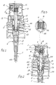
- the micropump for the nebulisation of fluids according to the invention is mounted on cap 42, destined to be screwed, with the interposition of a gasket seal 44, on the neck of a bottle not shown.
- the micropump includes the hollow body 1.
- the hollow body 1 is an extended container, open at both its ends. In its lower end opening is inserted the suction tube 43, destined to be immersed in the fluid to be nebulised.
- the hollow body 1 is fitted at its bottom with a ball check valve 11 and it is closed at the top with a flange 12 connecting to the bottle cap 42.
- the stem and piston set 2 within the hollow body comprises a "metering chamber” 21 in the lower part of the hollow body 1, i.e. the one delimited by the ball valve 11.
- the stem and piston set 2 comprises a hollow stem 5, with inner cavity 55, which protrudes, at the rear, from the hollow body 1 through a flange 12 providing connection to the cap 42.
- the hollow stem 5 is joined at the rear to the dispensing push-button 3, conformed with diametrical baffles, like the one indicated with 31, in an inner crown such as to provide abutment for the hollow stem 5.
- the dispensing push-button 3 therefore presents a so-called “compression pre-chamber” 6 with passages 7 to an orifice 41 of the nebulisation element or insert 4, wherein a "vortex chamber" is provided.
- the hollow stem 5 presents in appropriate position a flange projection 51 abutting against the connecting flange 12, whereon a gasket seal 13 is provided.
- the hollow stem 5 presents, in its front portion, a distinct head 52.
- On the head 52 abuts an end of a helical spring 25, whose other end abuts against the lower portion of the hollow body 1.
- the hollow stem 5 and its head 52 have such a structure as to allow the insertion onto the hollow stem 5 of a piston 53.
- the piston 53 is externally shaped with circumferential lips for sealing the inner surface of the hollow body 1, whilst internally it presents two portions of different diameter for its limited sliding on corresponding portions of the hollow stem 5.
- Conventionally, in the hollow stem portion 5 next to the head 52 is provided at least one through hole 54, which places in communication the "metering chamber" 21 with the interior of the hollow stem 5.
- the hollow stem 5 presents in its rear end a seat 56 for an elastically deformable shutter, constructed in the shape of a cylindrical dowel 8.
- the dowel 8 which may also have any other appropriate shape, is interposed in the exit duct of the fluids to be nebulised coming from the suction tube 43. From the "metering chamber” 21 through one or more holes 54, the exit duct develops in the longitudinal cavity 55 of the hollow stem, in the seat 56 for the shutter, in the "compression pre-chamber" 6 and in the passages 7 of the dispensing push-button 3 to the exit orifice 41 of the nebulisation element 4.
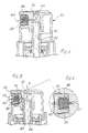
- the dowel 8 is transformed from its non-deformed condition of Figure 1, when the pressure within the longitudinal cavity 55 is lower than the minimum or threshold pressure for nebulisation, to the elastically deformed condition of Figures 2 and 3.
- the fluids pass beyond the seat 56 of the dowel 8, lapping it (as shown schematically by the flow lines in Figure 3), reach the "compression pre-chamber" 6, and hence the passages 7 through to the exit orifice 41.
- the pressure in the longitudinal chamber 55 and in the "metering chamber” 2 1 drops below the minimum or threshold value regulated by the rigidity of the dowel 8, which closes the fluid exit duct.
- the user releases the dispensing push-button 3 which, moving back upwards, increases the vacuum in the "metering chamber” 21.
- the ball valve 11 opens the passage from the suction tube 43 and new fluid passes from the bottle to the "metering chamber” 21 of the micropump for subsequent nebulisation upon repeated pressing of the dispensing push-button 3.
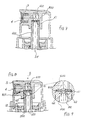
- the shutter is a cylindrical dowel 80 made of elastomeric material positioned within a nebulisation element 40 coaxially to a passage 70 between a "compression pre-chamber" 60 and a nebulisation element orifice 410 in a dispensing push-button structure 30, modified with respect to that of the first embodiment.
- the longitudinal cavity 55 of a hollow stem 500 is closed, in proximity with a "compression pre-chamber” 600, with a baffle 61, provided with a plurality of circumferential holes 62.
- the baffle 61 is obtained in a single piece with the hollow stem 500.
- the shutter is a disk or platelet 800 with a hole in its centre, positioned facing the baffle 61 in proximity to the "compression pre-chamber" 600.
- the pressurised fluid deforms the baffle 61 upward and flows past the circumferential holes 62.
- the shutter must present a rigidity suitably adjusted to allow for easy dispensing.
Landscapes
- Containers And Packaging Bodies Having A Special Means To Remove Contents (AREA)
- Closures For Containers (AREA)
- Reciprocating Pumps (AREA)
- Physical Or Chemical Processes And Apparatus (AREA)
Applications Claiming Priority (2)
| Application Number | Priority Date | Filing Date | Title |
|---|---|---|---|
| IT97RM000177A IT1291122B1 (it) | 1997-03-28 | 1997-03-28 | Micropompa per la nebulizzazione di fluidi con valvola dosatrice perfezionata |
| ITRM970177 | 1997-03-28 |
Publications (3)
| Publication Number | Publication Date |
|---|---|
| EP0867232A2 true EP0867232A2 (fr) | 1998-09-30 |
| EP0867232A3 EP0867232A3 (fr) | 1999-04-14 |
| EP0867232B1 EP0867232B1 (fr) | 2004-05-26 |
Family
ID=11404916
Family Applications (1)
| Application Number | Title | Priority Date | Filing Date |
|---|---|---|---|
| EP98830180A Expired - Lifetime EP0867232B1 (fr) | 1997-03-28 | 1998-03-26 | Micropompe munie d'une valve doseuse pour la nébulisation de fluides |
Country Status (9)
| Country | Link |
|---|---|
| US (1) | US6016974A (fr) |
| EP (1) | EP0867232B1 (fr) |
| CN (1) | CN1201117A (fr) |
| AR (1) | AR018492A1 (fr) |
| BR (1) | BR9801210A (fr) |
| DE (1) | DE69824069D1 (fr) |
| ID (1) | ID20125A (fr) |
| IT (1) | IT1291122B1 (fr) |
| TW (1) | TW393430B (fr) |
Cited By (1)
| Publication number | Priority date | Publication date | Assignee | Title |
|---|---|---|---|---|
| GB2474360A (en) * | 2009-10-09 | 2011-04-13 | Univ Salford | Metering valve with liquid discharge element |
Families Citing this family (21)
| Publication number | Priority date | Publication date | Assignee | Title |
|---|---|---|---|---|
| FR2791400B1 (fr) * | 1999-03-22 | 2002-04-26 | Sofab | Pompe a reaspiration |
| DE10108486A1 (de) * | 2001-02-22 | 2002-09-19 | Steven Padar | Abgabevorrichtung für Fluide |
| US6832704B2 (en) | 2002-06-17 | 2004-12-21 | Summit Packaging Systems, Inc. | Metering valve for aerosol container |
| US20070045349A1 (en) * | 2005-08-25 | 2007-03-01 | Continental Afa Dispensing Company | Liquid dispensing pump with shifting liquid piston |
| JP4873006B2 (ja) * | 2006-03-30 | 2012-02-08 | 株式会社三谷バルブ | 内容物放出用のポンプ機構およびこのポンプ機構を備えたポンプ式製品 |
| US8353864B2 (en) * | 2009-02-18 | 2013-01-15 | Davis David L | Low cost disposable infusion pump |
| US8197235B2 (en) * | 2009-02-18 | 2012-06-12 | Davis David L | Infusion pump with integrated permanent magnet |
| US20100211002A1 (en) * | 2009-02-18 | 2010-08-19 | Davis David L | Electromagnetic infusion pump with integral flow monitor |
| US8618164B2 (en) | 2009-03-31 | 2013-12-31 | Nuvo Research Inc. | Treatment of pain with topical diclofenac compounds |
| IT1397007B1 (it) * | 2009-12-15 | 2012-12-20 | Emsar Spa | Dispenser |
| DE102010048986A1 (de) * | 2010-10-20 | 2012-04-26 | Ursapharm Arzneimittel Gmbh | Dosierpumpe |
| US20140113970A1 (en) * | 2012-10-22 | 2014-04-24 | Mallinckrodt LLC Covidien | Dispensing system |
| FR3000945B1 (fr) * | 2013-01-15 | 2016-02-05 | Lindal France | Valve doseuse |
| KR102698051B1 (ko) | 2015-02-27 | 2024-08-26 | 더 보드 오브 리젠츠 오브 더 유니버시티 오브 텍사스 시스템 | 폴리펩타이드 치료제 및 이의 용도 |
| WO2020055812A1 (fr) | 2018-09-10 | 2020-03-19 | Lung Therapeutics, Inc. | Fragments de peptides modifiés de la protéine cav-1, et utilisation de ces derniers dans le traitement de la fibrose |
| EP3937966B1 (fr) | 2019-03-11 | 2026-05-06 | Rein Therapeutics, Inc. | Compositions et procédés de protection de cellules épithéliales alvéolaires de type 2 (aec2) |
| WO2021191266A1 (fr) | 2020-03-25 | 2021-09-30 | INSERM (Institut National de la Santé et de la Recherche Médicale) | Aérosolisation de hdl pour traiter des infections pulmonaires |
| EP3892275A1 (fr) | 2020-04-08 | 2021-10-13 | INSERM (Institut National de la Santé et de la Recherche Médicale) | Production d'aérosols de hcq ou de ses métabolites pour le traitement d'infections pulmonaires |
| CN117504101A (zh) * | 2022-08-11 | 2024-02-06 | 天舟医疗(苏州)有限公司 | 一种多用途的喷雾装置 |
| WO2024246220A1 (fr) | 2023-05-31 | 2024-12-05 | Institut National de la Santé et de la Recherche Médicale | Méthodes et compositions pour le traitement du cancer du poumon |
| WO2026008645A1 (fr) | 2024-07-02 | 2026-01-08 | Institut National de la Santé et de la Recherche Médicale | Aérosolisation de nanoparticules d'apolipoprotéine a1 enrichie en alpha-1-antitrypsine pour le traitement de l'emphysème pulmonaire chez les patients souffrant d'une déficience en alpha-1 antitrypsine |
Family Cites Families (10)
| Publication number | Priority date | Publication date | Assignee | Title |
|---|---|---|---|---|
| DE1302372C2 (de) * | 1967-01-17 | 1978-06-08 | Pfeiffer Zerstäuber-Vertriebsgesellschaft mbH & Co KG, 7760 Radolfzell | In einem gefaess eingebaute einfachwirkende handbetaetigte schubkolbenpumpe |
| US3414169A (en) * | 1967-02-17 | 1968-12-03 | Diamond Int Corp | Liquid dispenser |
| FR2082807A5 (fr) * | 1970-03-26 | 1971-12-10 | Step Soc Tech Pulverisation | |
| US3769325A (en) * | 1970-12-10 | 1973-10-30 | Union Oil Co | Oxidation of alpha aryl alcohols |
| US3949939A (en) * | 1975-03-26 | 1976-04-13 | Smithkline Corporation | Metered spray device |
| FR2343137A1 (fr) * | 1976-03-01 | 1977-09-30 | Valois Sa | Pompe manuelle a piston pour distribution ou pulverisation |
| DE3839590A1 (de) * | 1988-11-24 | 1990-05-31 | Pfeiffer Erich Gmbh & Co Kg | Ventil, insbesondere fuer manuelle austragvorrichtungen |
| DE59104114D1 (de) * | 1990-04-09 | 1995-02-16 | Lir France Sa | Pumpvorrichtung für ein fliessfähiges, insbesondere pastöses und/oder flüssiges Produkt und Spender mit einer solchen Pumpvorrichtung. |
| FR2705589B1 (fr) * | 1993-05-28 | 1995-07-28 | Valois | Buse de pulvérisation et pulvérisateur comportant une telle buse. |
| IT1269860B (it) * | 1994-05-30 | 1997-04-15 | Tommaso Ruscitti | Pompetta a struttura semplificata, per l'erogazione di fluidi sotto pressione |
-
1997
- 1997-03-28 IT IT97RM000177A patent/IT1291122B1/it active IP Right Grant
-
1998
- 1998-03-26 EP EP98830180A patent/EP0867232B1/fr not_active Expired - Lifetime
- 1998-03-26 DE DE69824069T patent/DE69824069D1/de not_active Expired - Lifetime
- 1998-03-27 TW TW087104631A patent/TW393430B/zh not_active IP Right Cessation
- 1998-03-27 AR ARP980101414A patent/AR018492A1/es active IP Right Grant
- 1998-03-27 US US09/049,118 patent/US6016974A/en not_active Expired - Lifetime
- 1998-03-27 CN CN98108733A patent/CN1201117A/zh active Pending
- 1998-03-30 ID IDP980471A patent/ID20125A/id unknown
- 1998-03-30 BR BR9801210A patent/BR9801210A/pt not_active IP Right Cessation
Non-Patent Citations (1)
| Title |
|---|
| None |
Cited By (3)
| Publication number | Priority date | Publication date | Assignee | Title |
|---|---|---|---|---|
| GB2474360A (en) * | 2009-10-09 | 2011-04-13 | Univ Salford | Metering valve with liquid discharge element |
| GB2474360B (en) * | 2009-10-09 | 2012-04-11 | Univ Salford | Liquid dispensing apparatus |
| US8820589B2 (en) | 2009-10-09 | 2014-09-02 | The University Of Salford | Liquid dispensing apparatus |
Also Published As
| Publication number | Publication date |
|---|---|
| AR018492A1 (es) | 2001-11-28 |
| CN1201117A (zh) | 1998-12-09 |
| DE69824069D1 (de) | 2004-07-01 |
| ID20125A (id) | 1998-10-08 |
| TW393430B (en) | 2000-06-11 |
| ITRM970177A1 (it) | 1998-09-28 |
| IT1291122B1 (it) | 1998-12-29 |
| EP0867232B1 (fr) | 2004-05-26 |
| BR9801210A (pt) | 1999-05-18 |
| EP0867232A3 (fr) | 1999-04-14 |
| US6016974A (en) | 2000-01-25 |
Similar Documents
| Publication | Publication Date | Title |
|---|---|---|
| EP0867232B1 (fr) | Micropompe munie d'une valve doseuse pour la nébulisation de fluides | |
| EP0867231B1 (fr) | Micropompe pour la nébulisation de fluides | |
| US4230242A (en) | Triple seal valve member for an atomizing pump dispenser | |
| CA1246504A (fr) | Pompe de prelevement d'un liquide sur son contenant | |
| US4735347A (en) | Single puff atomizing pump dispenser | |
| CA1056351A (fr) | Pompe a dispositif atomiseur | |
| US7267251B2 (en) | Draw back pump | |
| US6712243B2 (en) | Diaphragm pump | |
| US6932246B2 (en) | Assembly for packaging and dispensing a product, especially in the form of a sample | |
| US3176889A (en) | Pressurized dispenser with integral stem seal | |
| US4389003A (en) | Sliding inlet seal for an atomizing pump dispenser | |
| EP0307127A1 (fr) | Valve comportant une chambre de dosage compressible | |
| US7080759B2 (en) | Dispensing head and fluid product dispenser comprising same | |
| US5794822A (en) | Reciprocating fluid pump with improved bottle seal | |
| US3764046A (en) | Compressed air fluid product dispenser | |
| JP5095357B2 (ja) | ポンプ及びそれに取付ける容器 | |
| USRE33552E (en) | Dispensing valve | |
| US7503466B2 (en) | Pump and receptacle fitted therewith | |
| US20230092170A1 (en) | All Plastic High Pressure Pump | |
| US5992703A (en) | Dispenser for discharging media | |
| US5887763A (en) | Reciprocating fluid pump with bottle closure having inner and outer rim seals | |
| US8074845B2 (en) | Fluid product dispensing element and dispenser comprising one such element | |
| EP0866733A1 (fr) | Distributeur de liquides | |
| US3402864A (en) | Construction of valves for aerosols |
Legal Events
| Date | Code | Title | Description |
|---|---|---|---|
| PUAI | Public reference made under article 153(3) epc to a published international application that has entered the european phase |
Free format text: ORIGINAL CODE: 0009012 |
|
| AK | Designated contracting states |
Kind code of ref document: A2 Designated state(s): DE ES FR GB IT |
|
| AX | Request for extension of the european patent |
Free format text: AL;LT;LV;MK;RO;SI |
|
| PUAL | Search report despatched |
Free format text: ORIGINAL CODE: 0009013 |
|
| AK | Designated contracting states |
Kind code of ref document: A3 Designated state(s): AT BE CH DE DK ES FI FR GB GR IE IT LI LU MC NL PT SE |
|
| AX | Request for extension of the european patent |
Free format text: AL;LT;LV;MK;RO;SI |
|
| 17P | Request for examination filed |
Effective date: 19991007 |
|
| AKX | Designation fees paid |
Free format text: DE ES FR GB IT |
|
| 17Q | First examination report despatched |
Effective date: 20021018 |
|
| GRAP | Despatch of communication of intention to grant a patent |
Free format text: ORIGINAL CODE: EPIDOSNIGR1 |
|
| GRAS | Grant fee paid |
Free format text: ORIGINAL CODE: EPIDOSNIGR3 |
|
| GRAA | (expected) grant |
Free format text: ORIGINAL CODE: 0009210 |
|
| AK | Designated contracting states |
Kind code of ref document: B1 Designated state(s): DE ES FR GB IT |
|
| PG25 | Lapsed in a contracting state [announced via postgrant information from national office to epo] |
Ref country code: IT Free format text: LAPSE BECAUSE OF FAILURE TO SUBMIT A TRANSLATION OF THE DESCRIPTION OR TO PAY THE FEE WITHIN THE PRESCRIBED TIME-LIMIT;WARNING: LAPSES OF ITALIAN PATENTS WITH EFFECTIVE DATE BEFORE 2007 MAY HAVE OCCURRED AT ANY TIME BEFORE 2007. THE CORRECT EFFECTIVE DATE MAY BE DIFFERENT FROM THE ONE RECORDED. Effective date: 20040526 |
|
| REG | Reference to a national code |
Ref country code: GB Ref legal event code: FG4D |
|
| REF | Corresponds to: |
Ref document number: 69824069 Country of ref document: DE Date of ref document: 20040701 Kind code of ref document: P |
|
| PG25 | Lapsed in a contracting state [announced via postgrant information from national office to epo] |
Ref country code: DE Free format text: LAPSE BECAUSE OF FAILURE TO SUBMIT A TRANSLATION OF THE DESCRIPTION OR TO PAY THE FEE WITHIN THE PRESCRIBED TIME-LIMIT Effective date: 20040827 |
|
| PG25 | Lapsed in a contracting state [announced via postgrant information from national office to epo] |
Ref country code: ES Free format text: LAPSE BECAUSE OF FAILURE TO SUBMIT A TRANSLATION OF THE DESCRIPTION OR TO PAY THE FEE WITHIN THE PRESCRIBED TIME-LIMIT Effective date: 20040906 |
|
| ET | Fr: translation filed | ||
| PG25 | Lapsed in a contracting state [announced via postgrant information from national office to epo] |
Ref country code: GB Free format text: LAPSE BECAUSE OF NON-PAYMENT OF DUE FEES Effective date: 20050326 |
|
| PLBE | No opposition filed within time limit |
Free format text: ORIGINAL CODE: 0009261 |
|
| STAA | Information on the status of an ep patent application or granted ep patent |
Free format text: STATUS: NO OPPOSITION FILED WITHIN TIME LIMIT |
|
| 26N | No opposition filed |
Effective date: 20050301 |
|
| GBPC | Gb: european patent ceased through non-payment of renewal fee |
Effective date: 20050326 |
|
| PGFP | Annual fee paid to national office [announced via postgrant information from national office to epo] |
Ref country code: FR Payment date: 20120419 Year of fee payment: 15 |
|
| REG | Reference to a national code |
Ref country code: FR Ref legal event code: ST Effective date: 20131129 |
|
| PG25 | Lapsed in a contracting state [announced via postgrant information from national office to epo] |
Ref country code: FR Free format text: LAPSE BECAUSE OF NON-PAYMENT OF DUE FEES Effective date: 20130402 |