EP0867253A1 - Verfahren und Anlage zum Be- und Entladen von Elektroden einer Punktschweisszange bei einem Widerstandspunktschweissgerät - Google Patents
Verfahren und Anlage zum Be- und Entladen von Elektroden einer Punktschweisszange bei einem Widerstandspunktschweissgerät Download PDFInfo
- Publication number
- EP0867253A1 EP0867253A1 EP98400591A EP98400591A EP0867253A1 EP 0867253 A1 EP0867253 A1 EP 0867253A1 EP 98400591 A EP98400591 A EP 98400591A EP 98400591 A EP98400591 A EP 98400591A EP 0867253 A1 EP0867253 A1 EP 0867253A1
- Authority
- EP
- European Patent Office
- Prior art keywords
- electrode
- electrodes
- extraction
- separation
- clamp
- Prior art date
- Legal status (The legal status is an assumption and is not a legal conclusion. Google has not performed a legal analysis and makes no representation as to the accuracy of the status listed.)
- Granted
Links
- 238000003466 welding Methods 0.000 title claims abstract description 27
- 238000000034 method Methods 0.000 title claims abstract description 14
- 238000000605 extraction Methods 0.000 claims abstract description 65
- 238000000926 separation method Methods 0.000 claims abstract description 17
- 230000000717 retained effect Effects 0.000 claims abstract description 4
- 230000000694 effects Effects 0.000 claims description 7
- 208000031968 Cadaver Diseases 0.000 description 2
- 238000005520 cutting process Methods 0.000 description 2
- 238000012545 processing Methods 0.000 description 2
- 230000035939 shock Effects 0.000 description 2
- RYGMFSIKBFXOCR-UHFFFAOYSA-N Copper Chemical compound [Cu] RYGMFSIKBFXOCR-UHFFFAOYSA-N 0.000 description 1
- 230000000295 complement effect Effects 0.000 description 1
- 229910052802 copper Inorganic materials 0.000 description 1
- 239000010949 copper Substances 0.000 description 1
- 230000007797 corrosion Effects 0.000 description 1
- 238000005260 corrosion Methods 0.000 description 1
- 230000006866 deterioration Effects 0.000 description 1
- 238000006073 displacement reaction Methods 0.000 description 1
- 238000011065 in-situ storage Methods 0.000 description 1
- 238000009434 installation Methods 0.000 description 1
- 238000012423 maintenance Methods 0.000 description 1
- 238000004519 manufacturing process Methods 0.000 description 1
- 239000000463 material Substances 0.000 description 1
- 238000012544 monitoring process Methods 0.000 description 1
- 238000003908 quality control method Methods 0.000 description 1
- 229910000679 solder Inorganic materials 0.000 description 1
- 238000012795 verification Methods 0.000 description 1
Images



Classifications
-
- B—PERFORMING OPERATIONS; TRANSPORTING
- B23—MACHINE TOOLS; METAL-WORKING NOT OTHERWISE PROVIDED FOR
- B23K—SOLDERING OR UNSOLDERING; WELDING; CLADDING OR PLATING BY SOLDERING OR WELDING; CUTTING BY APPLYING HEAT LOCALLY, e.g. FLAME CUTTING; WORKING BY LASER BEAM
- B23K11/00—Resistance welding; Severing by resistance heating
- B23K11/30—Features relating to electrodes
- B23K11/3072—Devices for exchanging or removing electrodes or electrode tips
-
- B—PERFORMING OPERATIONS; TRANSPORTING
- B23—MACHINE TOOLS; METAL-WORKING NOT OTHERWISE PROVIDED FOR
- B23K—SOLDERING OR UNSOLDERING; WELDING; CLADDING OR PLATING BY SOLDERING OR WELDING; CUTTING BY APPLYING HEAT LOCALLY, e.g. FLAME CUTTING; WORKING BY LASER BEAM
- B23K11/00—Resistance welding; Severing by resistance heating
- B23K11/30—Features relating to electrodes
- B23K11/3063—Electrode maintenance, e.g. cleaning, grinding
Definitions
- the present invention relates to a method and a device for extraction and / or charging the electrodes of a welding gun resistance spot welding.
- these devices include two movable arms, one relative to the other and each carrying at one of its ends an electrode holder tip on which an electrode is forcibly engaged.
- the two electrodes that are connected to a source of electrical energy pinch the two parts to be welded, so that generate a high electric current inside the welding area intensity locally causing a rise in temperature, (by Joule effect) at a level corresponding to the welding temperature.
- the electrodes made of a material having a high conductivity electrical (such as copper), each includes a tubular body cylindrical extended on one side by a coaxial end ending in one side flat or curvilinear support intended to come to bear on one of the two parts to solder.
- a material having a high conductivity electrical such as copper
- the internal diameter of the tubular body is substantially complementary to that of the electrode holder so as to allow engagement conical force of the electrode on the support which secures the two pieces and which guarantees good conduction of electric current to the junction level.
- the tip has a shape of revolution (for example tapered) tapering from the body to the bearing face, so as to make the current lines converge towards the zones to be welded and to obtain, at these zones, the current density desired to reach the desired welding temperature.
- a shape of revolution for example tapered
- these welding electrodes are the site of intense wear which quickly causes deformations of the tip and, in particular, of the face support. This wear is notably due to the establishment of electric arcs which form between the electrode and the part and which eventually corrode the face support, it being understood that the more the electrode is deteriorated, the more it forms arcs, therefore the more intense the corrosion (with risk of deterioration of the parts to weld), and the less the quality of the weld is good.
- these devices involve shaped lapping heads substantially cylindrical and removably mounted in a tool holder ring coupled to a rotary drive device.
- the lapping head can be double so as to ability to process both electrodes from the same clamp at the same time.
- lapping head includes two opposite cavities with cutting edges whose profile corresponds to that of the end pieces that you want to run in. So when lapping, the two electrodes are arranged so as to pinch the head running-in, the two end caps respectively engaging in the two cavities. The rotation of the lapping head then causes a simultaneous lapping of the two end caps.
- the electrodes can only undergo a limited number of laps, beyond which it becomes necessary to replace them. The operator can then take advantage of this replacement phase to perform quality control of the running-in of the electrodes.
- this electrode replacement phase is particularly delicate because it involves an extraction of the electrode out of its support.
- the electrode adheres firmly to its support due from the initial force engagement and then to the welding effects by thermocompression exerted during welding. It is therefore frequently necessary to exert impacts on the used electrode properly oriented to cause takeoff. This is the reason the automation of this replacement phase is difficult to envisage.
- the separation phase may also include the application of an impact on the extraction parts as well as, if necessary, a tensile force exerted on the electrode holders.
- a new electrode can be force-fitted on each electrode holder.
- This engagement may be carried out simultaneously on both supports, placing the two electrodes coaxially, close to each other, with the tips facing each other, and closing the clamp at the end a displacement leading the two electrode holders to be disposed coaxially to the axis of the two electrodes and then to forcely engage in it under the effect of the torque exerted by the clamp.
- the method according to the invention may also comprise a phase prior to running in the electrodes and after extraction, a verification of the running-in quality.
- the invention also relates to an apparatus allowing to carry out a sequence of extraction, replacement and possibly running-in according to the process described above.
- the electrode 1 comprises a body tubular 2, open on one side at an annular radial face 3 and extended, on the other side, by a nozzle 4 having a profile of revolution stepped comprising two successive chamfers 5, 6 ending in a shape domed 7.
- This electrode 1 is intended to force engage on the end cylindrical 8 of an electrode holder 8 ', of diameter substantially equal to the internal diameter of the body 2 so as to secure it by jamming of the two parts.
- the invention uses the space E between the annular radial face 3 of the electrode and a stop element 9 (here a circular shoulder) to carry out the extraction of the electrode 1: It proposes engage in this space E a wedge-shaped extraction part 10, movable perpendicular to the axis of the electrode holder 8 'so as to be able to exert on the electrode 1 and on said electrode holder 8' two opposing forces F 1 , F 2 oriented axially, so as to produce an extraction force from the electrode 1.
- the extraction part 10 may have the shape of a fork (FIG.
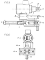
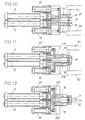
- the apparatus for extracting, installing and running in electrodes illustrated in FIGS. 5 to 13, is more particularly designed to simultaneously treat the two electrodes 1 ′, 1 "of a welding clamp of an apparatus (by example an automatic welding device) of which only the two arms B 1 , B 2 have been shown.
- These two arms B 1 , B 2 are movable relative to each other and are actuated by a mechanism so as to be able to assume a closed position in which the two electrodes 1 ′, 1 ′′ are arranged coaxially one by relative to each other, at a distance from each other which may for example correspond to the thickness of the parts to be welded, and an open position in which the electrodes 1 ′, 1 ′′ are spaced apart from one another 'other.
- This mechanism is more particularly designed so as to exert opening and closing maneuvers with relatively high forces (extraction, pinching), in different locations.
- the apparatus comprises three superposed treatment stations, namely: a lapping station for the electrodes P 1 , a station for placing the electrodes on the electrode holders 8 ′ and an extraction / ejection station P 3 of the used electrodes.
- the processing is carried out simultaneously on the two electrodes 1 ', 1 "of the clamp and involves a clamping phase by the electrodes 1 ', 1 "of a support piece possibly equipped with means of guidance, centering and / or processing.
- the break-in station P 1 is made up of a pneumatic or electric gearmotor M, an output pinion of which meshes with a toothed ring tool holder rotatably mounted in a flat parallelepiped housing BP which axially extends the body of the gearmotor M.
- the two opposite main faces of the BP housing are provided with two circular openings O coaxial with the toothed wheel and of substantially diameter equal to the average diameter of this behind.
- the BP box is therefore crossed right through by a passage cylindrical essentially bounded by the inner surface of the crown and in which a double lapping head can be engaged, for example of the type of that which is described in the French patent application No 96 14505 filed November 22, 1996.
- the clamp electrodes are brought coaxially, on either side of the tool holder ring (opening O).
- the tightening carried out by the clamp then causes the engagement of the electrodes 1 ', 1 "in contact with the cutting profiles of the lapping head.
- the rotary drive of the tool holder ring then causes the simultaneous running in of the two electrodes.
- the station P 2 for placing the electrodes on the electrode holders of the clamp consists of a double electrode distributor D comprising an elongated body 15, the two lateral faces 16 , 17 are provided with two parallel concavities 18, 19 forming a slide whose transverse profile corresponds substantially to the profile of an electrode 1.
- These two concavities 18, 19 are oriented opposite one another so as to contain two series of coaxial electrodes 1, the orifices of which open outwards.
- the two sets of electrodes 1 are respectively subjected to the action of two pushers 23 which each exert a push on the electrode situated at one end of a series, while that the electrode located at the other end of the series comes to bear on an abutment and centering surface 24 of the body 15.
- the two electrodes bearing on these abutment surfaces are arranged coaxially, in line with circular orifices coaxial C 1 , C 2 formed in the two lateral wings 20, 21 of the cover 22.
- each pusher 23 comprises a jack V 1 , the rod T of which ends in a curved support piece coming into contact with the first electrode 1 in the series.
- the clamp is first of all placed so that the two electrode holders are arranged coaxially with the two orifices C 1 , C 2 and close to them. The clamp is then closed. During this closing, the two electrode holders force-engage simultaneously in the electrodes located coaxially with the orifices C 1 , C 2 which are in abutment on the abutment surfaces 24. Once the engagement has been carried out, we proceed when opening the clamp. During this opening, the two electrodes 1 remain fixed on the electrode holders and are extracted from the distributor by the orifices C 1 , C 2 . The penultimate electrodes of the two rows then occupy the place of the two electrodes which have just been extracted.
- the electrode placement device is then ready for reuse.
- the reloading of the two slides can be carried out by removing the cover 22 and retracting the pusher associated with the rod T of the jack V 1 .
- Each of the carriages CH 1 , CH 2 is actuated by a jack V 2 and can move along the slides 33, 34 so that the extraction part 10 can engage on either side of a electrode 1 positioned in the corresponding cavity 31, 32 of the centering piece 30, in the groove formed between the electrode 1 and the shoulder 9 of the electrode holder 8 '.
- the carriage CH 1 , CH 2 is arranged in the axis of an impactor I 1 , I 2 designed so as to be able to exert an impact at the rear of the carriage CH 1 , CH 2 , in the direction of the workpiece centering 30, when the extraction part 10, engaged in the groove exerts a wedge effect between the electrode 1 and the shoulder 9.
- This shock makes it possible to produce a separation between the electrode 1 and the electrode holder 8 '.
- the two cavities 31, 32 communicate with each other through a passage in which is disposed an ejector EX actuated by a jack V 3 .
- the welding tongs (arm B 1 , B 2 ) are brought into a position such that the electrodes 1 ′, 1 ′′ come to be arranged coaxially with the cavities 31, 32.
- the clamp is then closed until that the two electrodes 1 ', 1 "are arranged and centered in the two cavities 31, 32.
- the profile of these cavities 31, 32 is designed so that the annular faces 3 of the electrodes 1, 1' which are held supported by their chamfer 5 on corresponding chamfered surfaces of the cavities 31, 32, level the plane of the lateral faces L 1 , L 2 of the centering piece 30.
- the cylinders V 2 are in the retracted state while the extraction parts 10 are located at a distance from the cavities (FIG. 7). Once the electrodes 1 ′, 1 ′′ correctly positioned in the cavities 31, 32, the two cylinders V 2 are actuated so as to move the carriages CH 1 , CH 2 to thereby engage the wedge-shaped part of the workpiece. extraction 10 in the throat (space E).
- the clamp performs its opening stroke while releasing electrodes which remain retained by the extraction parts (figure 10).
- the electrodes fall into a hopper (not shown) and are brought to a control station, for example through a conduit for examination.
- the purpose of this examination may in particular be to check the quality of the running-in performed at the running-in station P 1 .
- a final running-in is carried out just before the extraction.
Landscapes
- Engineering & Computer Science (AREA)
- Mechanical Engineering (AREA)
- Arc Welding In General (AREA)
- Resistance Welding (AREA)
Applications Claiming Priority (2)
| Application Number | Priority Date | Filing Date | Title |
|---|---|---|---|
| FR9703807A FR2761285B1 (fr) | 1997-03-26 | 1997-03-26 | Procede et dispositif pour l'extraction et/ou le chargement des electrodes d'une pince a souder d'un appareil de soudage par points par resistance |
| FR9703807 | 1997-03-26 |
Publications (2)
| Publication Number | Publication Date |
|---|---|
| EP0867253A1 true EP0867253A1 (de) | 1998-09-30 |
| EP0867253B1 EP0867253B1 (de) | 2002-01-16 |
Family
ID=9505272
Family Applications (1)
| Application Number | Title | Priority Date | Filing Date |
|---|---|---|---|
| EP19980400591 Expired - Lifetime EP0867253B1 (de) | 1997-03-26 | 1998-03-12 | Verfahren und Anlage zum Be- und Entladen von Elektroden einer Punktschweisszange bei einem Widerstandspunktschweissgerät |
Country Status (3)
| Country | Link |
|---|---|
| EP (1) | EP0867253B1 (de) |
| DE (1) | DE69803133D1 (de) |
| FR (1) | FR2761285B1 (de) |
Cited By (7)
| Publication number | Priority date | Publication date | Assignee | Title |
|---|---|---|---|---|
| WO2000044524A1 (fr) * | 1999-02-01 | 2000-08-03 | Societe Financiere D'etude Et De Developpement Industriel Et Technologique | Dispositif pour changer une electrode usee d'une pince de soudage d'un robot de soudage |
| FR2788999A1 (fr) * | 1999-02-01 | 2000-08-04 | Sofedit | Dispositif pour changer une electrode usee d'une pince de soudage d'un robot de soudage |
| FR2802455A1 (fr) * | 1999-12-20 | 2001-06-22 | Cerval S A | Dispositif d'extracteur d'electrode |
| FR2854337A1 (fr) * | 2003-04-30 | 2004-11-05 | Serv | Module d'extraction pour robot de soudage |
| EP1358962A3 (de) * | 2002-04-29 | 2004-11-10 | Robtex Inc. | Verfahren und Vorrichtung zum Entfernen und Auswechseln von Schweisselektrodenkappen |
| CN100534695C (zh) * | 2003-07-23 | 2009-09-02 | 小原株式会社 | 固定式电极头拆卸装置 |
| US20150038306A1 (en) * | 2013-02-13 | 2015-02-05 | Korea T&M Co., Ltd. | Apparatus for changing welding tip |
Families Citing this family (2)
| Publication number | Priority date | Publication date | Assignee | Title |
|---|---|---|---|---|
| WO2014033253A1 (de) | 2012-08-31 | 2014-03-06 | Matuschek Messtechnik Gmbh | Vorrichtung und verfahren zum schleifen von werkstücken, insbesondere schweisselektroden |
| DE102014203409B4 (de) | 2014-02-25 | 2017-08-24 | Matuschek Meßtechnik GmbH | Vorrichtung und Verfahren zum Schleifen von starren, metallischen Schweißelektroden für das Widerstandsschweißen |
Citations (8)
| Publication number | Priority date | Publication date | Assignee | Title |
|---|---|---|---|---|
| DE3323038A1 (de) * | 1983-06-25 | 1985-01-10 | Bayerische Motoren Werke AG, 8000 München | Vorrichtung zum selbsttaetigen auswechseln des endstuecks einer schweisselektrode |
| US4649613A (en) * | 1985-09-09 | 1987-03-17 | Bednarik Richard J | Welding tip removal tool |
| EP0267109A1 (de) * | 1986-11-06 | 1988-05-11 | Automobiles Peugeot | Automatische Schweissroboterelektrodenwechselvorrichtung |
| US4794221A (en) * | 1986-11-26 | 1988-12-27 | Toyota Jidosha Kabushiki Kaisha | Apparatus and method for exchanging electrode chips used for resistance welding |
| US5073692A (en) * | 1990-11-13 | 1991-12-17 | Jackson Donald T | Automatic welding electrode cap changer |
| FR2683172A1 (fr) * | 1991-11-06 | 1993-05-07 | Rigaux Pierre | Module de dechargement d'electrodes de soudage et dispositif de dechargement/chargement comportant ledit module. |
| US5495663A (en) * | 1993-06-04 | 1996-03-05 | Saito; Akihiro | Apparatus for removing an electrode chip from a shank of a resistance welding machine |
| FR2738518A1 (fr) * | 1995-09-08 | 1997-03-14 | Amdp | Tete de rodage amovible pour le rodage d'electrodes d'appareils de soudage |
-
1997
- 1997-03-26 FR FR9703807A patent/FR2761285B1/fr not_active Expired - Fee Related
-
1998
- 1998-03-12 DE DE69803133T patent/DE69803133D1/de not_active Expired - Lifetime
- 1998-03-12 EP EP19980400591 patent/EP0867253B1/de not_active Expired - Lifetime
Patent Citations (8)
| Publication number | Priority date | Publication date | Assignee | Title |
|---|---|---|---|---|
| DE3323038A1 (de) * | 1983-06-25 | 1985-01-10 | Bayerische Motoren Werke AG, 8000 München | Vorrichtung zum selbsttaetigen auswechseln des endstuecks einer schweisselektrode |
| US4649613A (en) * | 1985-09-09 | 1987-03-17 | Bednarik Richard J | Welding tip removal tool |
| EP0267109A1 (de) * | 1986-11-06 | 1988-05-11 | Automobiles Peugeot | Automatische Schweissroboterelektrodenwechselvorrichtung |
| US4794221A (en) * | 1986-11-26 | 1988-12-27 | Toyota Jidosha Kabushiki Kaisha | Apparatus and method for exchanging electrode chips used for resistance welding |
| US5073692A (en) * | 1990-11-13 | 1991-12-17 | Jackson Donald T | Automatic welding electrode cap changer |
| FR2683172A1 (fr) * | 1991-11-06 | 1993-05-07 | Rigaux Pierre | Module de dechargement d'electrodes de soudage et dispositif de dechargement/chargement comportant ledit module. |
| US5495663A (en) * | 1993-06-04 | 1996-03-05 | Saito; Akihiro | Apparatus for removing an electrode chip from a shank of a resistance welding machine |
| FR2738518A1 (fr) * | 1995-09-08 | 1997-03-14 | Amdp | Tete de rodage amovible pour le rodage d'electrodes d'appareils de soudage |
Cited By (9)
| Publication number | Priority date | Publication date | Assignee | Title |
|---|---|---|---|---|
| WO2000044524A1 (fr) * | 1999-02-01 | 2000-08-03 | Societe Financiere D'etude Et De Developpement Industriel Et Technologique | Dispositif pour changer une electrode usee d'une pince de soudage d'un robot de soudage |
| FR2788999A1 (fr) * | 1999-02-01 | 2000-08-04 | Sofedit | Dispositif pour changer une electrode usee d'une pince de soudage d'un robot de soudage |
| FR2789001A1 (fr) * | 1999-02-01 | 2000-08-04 | Financ D Etudes Et De Dev Ind | Dispositif pour changer une electrode usee d'une pince de soudage d'un robot de soudage |
| FR2802455A1 (fr) * | 1999-12-20 | 2001-06-22 | Cerval S A | Dispositif d'extracteur d'electrode |
| EP1358962A3 (de) * | 2002-04-29 | 2004-11-10 | Robtex Inc. | Verfahren und Vorrichtung zum Entfernen und Auswechseln von Schweisselektrodenkappen |
| FR2854337A1 (fr) * | 2003-04-30 | 2004-11-05 | Serv | Module d'extraction pour robot de soudage |
| CN100534695C (zh) * | 2003-07-23 | 2009-09-02 | 小原株式会社 | 固定式电极头拆卸装置 |
| US20150038306A1 (en) * | 2013-02-13 | 2015-02-05 | Korea T&M Co., Ltd. | Apparatus for changing welding tip |
| US9744626B2 (en) * | 2013-02-13 | 2017-08-29 | Korea T&M Co. Ltd. | Apparatus for changing welding tip |
Also Published As
| Publication number | Publication date |
|---|---|
| FR2761285B1 (fr) | 1999-06-04 |
| EP0867253B1 (de) | 2002-01-16 |
| FR2761285A1 (fr) | 1998-10-02 |
| DE69803133D1 (de) | 2002-02-21 |
Similar Documents
| Publication | Publication Date | Title |
|---|---|---|
| EP3061558B1 (de) | Reibrührschweißverfahren zum Reparieren eines Schweißdefekts | |
| EP2647462B1 (de) | Elektrodenwechsler mit translatorischem Antrieb von Greiffern | |
| FR2685235A1 (fr) | Electrode de soudage a resistance par points; extremite de contact pour une telle electrode; machine pour l'echange de ces extremites. | |
| EP0867253B1 (de) | Verfahren und Anlage zum Be- und Entladen von Elektroden einer Punktschweisszange bei einem Widerstandspunktschweissgerät | |
| FR2488169A1 (fr) | Ensemble d'un coulisseau et d'un porte-outil pour tour vertical ou machine analogue | |
| FR2732633A1 (fr) | Procede et dispositif de changement d'outil pour un centre d'usinage | |
| FR2710788A1 (fr) | Outil de sertissage pour le raccordement d'un câble électrique dans un élément d'extrémité. | |
| FR2511279A1 (fr) | Machine a souder des tuyaux bout a bout par resistance | |
| CH647360A5 (fr) | Procede et dispositif pour realiser une broche de connecteur electrique. | |
| EP0267109B1 (de) | Automatische Schweissroboterelektrodenwechselvorrichtung | |
| EP1516412B1 (de) | Vorrichtung zum greifen und umsetzen von leiterbündeln zur wicklungherstellung, und verfahren zur herstellung einer wicklung mit solcher vorrichtung | |
| EP3381596B1 (de) | Maschine und verfahren zur maschinellen bearbeitung durch elektroerosion einer gerotor-pumpe | |
| FR2738518A1 (fr) | Tete de rodage amovible pour le rodage d'electrodes d'appareils de soudage | |
| EP0320357B1 (de) | Maschine zum Entfernen des Abstandsdrahtes von Kernbrennstäben | |
| EP2138261A1 (de) | Schweissen von Haltestücken für einen Griffbückel auf eine mit einem nicht-leitendem Material beschichteten Wandung | |
| FR2482498A1 (fr) | Procede et dispositif pour remettre automatiquement en place un fil electrode sur une machine d'electroerosion | |
| EP0574729B1 (de) | Schachtofenabstichmaschine | |
| FR2921855A1 (fr) | Dispositif d'extraction d'electrode de robot de soudure et ensemble d'extraction | |
| FR2845938A1 (fr) | Procede pour l'extraction et/ou le changement des electrodes d'une pince a souder ou d'un appareil de soudage | |
| CH675507A5 (de) | ||
| FR2490974A1 (fr) | Ensemble pour la fabrication de pieces par moulage sous pression ou par injection | |
| EP0968070A1 (de) | Vorrichtung für die wartung von programmierbaren robotern | |
| EP0041464B1 (de) | Anschlagschlitten für ein Walzwerk | |
| FR2672831A1 (fr) | Machine de soudage par friction a haute cadence. | |
| EP0109691A1 (de) | Trommelwurzelschneider |
Legal Events
| Date | Code | Title | Description |
|---|---|---|---|
| PUAI | Public reference made under article 153(3) epc to a published international application that has entered the european phase |
Free format text: ORIGINAL CODE: 0009012 |
|
| AK | Designated contracting states |
Kind code of ref document: A1 Designated state(s): BE DE ES GB IT PT SE |
|
| AX | Request for extension of the european patent |
Free format text: AL;LT;LV;MK;RO;SI |
|
| 17P | Request for examination filed |
Effective date: 19990219 |
|
| AKX | Designation fees paid |
Free format text: BE DE ES GB IT PT SE |
|
| GRAG | Despatch of communication of intention to grant |
Free format text: ORIGINAL CODE: EPIDOS AGRA |
|
| RTI1 | Title (correction) |
Free format text: METHOD AND DEVICE FOR EXTRACTING AND SUPPLYING THE ELECTRODES OF/TO AN ELECTRODE GUN OF A RESISTANCE SPOT WELDING APPARATUS |
|
| 17Q | First examination report despatched |
Effective date: 20010516 |
|
| GRAG | Despatch of communication of intention to grant |
Free format text: ORIGINAL CODE: EPIDOS AGRA |
|
| GRAH | Despatch of communication of intention to grant a patent |
Free format text: ORIGINAL CODE: EPIDOS IGRA |
|
| GRAH | Despatch of communication of intention to grant a patent |
Free format text: ORIGINAL CODE: EPIDOS IGRA |
|
| GRAA | (expected) grant |
Free format text: ORIGINAL CODE: 0009210 |
|
| REG | Reference to a national code |
Ref country code: GB Ref legal event code: IF02 |
|
| AK | Designated contracting states |
Kind code of ref document: B1 Designated state(s): BE DE ES GB IT PT SE |
|
| PG25 | Lapsed in a contracting state [announced via postgrant information from national office to epo] |
Ref country code: IT Free format text: LAPSE BECAUSE OF FAILURE TO SUBMIT A TRANSLATION OF THE DESCRIPTION OR TO PAY THE FEE WITHIN THE PRESCRIBED TIME-LIMIT;WARNING: LAPSES OF ITALIAN PATENTS WITH EFFECTIVE DATE BEFORE 2007 MAY HAVE OCCURRED AT ANY TIME BEFORE 2007. THE CORRECT EFFECTIVE DATE MAY BE DIFFERENT FROM THE ONE RECORDED. Effective date: 20020116 Ref country code: GB Free format text: LAPSE BECAUSE OF FAILURE TO SUBMIT A TRANSLATION OF THE DESCRIPTION OR TO PAY THE FEE WITHIN THE PRESCRIBED TIME-LIMIT Effective date: 20020116 |
|
| REF | Corresponds to: |
Ref document number: 69803133 Country of ref document: DE Date of ref document: 20020221 |
|
| PG25 | Lapsed in a contracting state [announced via postgrant information from national office to epo] |
Ref country code: BE Free format text: LAPSE BECAUSE OF NON-PAYMENT OF DUE FEES Effective date: 20020331 |
|
| PG25 | Lapsed in a contracting state [announced via postgrant information from national office to epo] |
Ref country code: SE Free format text: LAPSE BECAUSE OF FAILURE TO SUBMIT A TRANSLATION OF THE DESCRIPTION OR TO PAY THE FEE WITHIN THE PRESCRIBED TIME-LIMIT Effective date: 20020416 Ref country code: PT Free format text: LAPSE BECAUSE OF FAILURE TO SUBMIT A TRANSLATION OF THE DESCRIPTION OR TO PAY THE FEE WITHIN THE PRESCRIBED TIME-LIMIT Effective date: 20020416 |
|
| PG25 | Lapsed in a contracting state [announced via postgrant information from national office to epo] |
Ref country code: DE Free format text: LAPSE BECAUSE OF FAILURE TO SUBMIT A TRANSLATION OF THE DESCRIPTION OR TO PAY THE FEE WITHIN THE PRESCRIBED TIME-LIMIT Effective date: 20020417 |
|
| GBV | Gb: ep patent (uk) treated as always having been void in accordance with gb section 77(7)/1977 [no translation filed] |
Effective date: 20020116 |
|
| PG25 | Lapsed in a contracting state [announced via postgrant information from national office to epo] |
Ref country code: ES Free format text: LAPSE BECAUSE OF FAILURE TO SUBMIT A TRANSLATION OF THE DESCRIPTION OR TO PAY THE FEE WITHIN THE PRESCRIBED TIME-LIMIT Effective date: 20020730 |
|
| BERE | Be: lapsed |
Owner name: *AMDP Effective date: 20020331 |
|
| PLBE | No opposition filed within time limit |
Free format text: ORIGINAL CODE: 0009261 |
|
| STAA | Information on the status of an ep patent application or granted ep patent |
Free format text: STATUS: NO OPPOSITION FILED WITHIN TIME LIMIT |
|
| 26N | No opposition filed |