EP0867320A2 - Dispositif de conditionnement d'air - Google Patents
Dispositif de conditionnement d'air Download PDFInfo
- Publication number
- EP0867320A2 EP0867320A2 EP97121767A EP97121767A EP0867320A2 EP 0867320 A2 EP0867320 A2 EP 0867320A2 EP 97121767 A EP97121767 A EP 97121767A EP 97121767 A EP97121767 A EP 97121767A EP 0867320 A2 EP0867320 A2 EP 0867320A2
- Authority
- EP
- European Patent Office
- Prior art keywords
- batch
- desiccant
- air conditioning
- conditioning system
- line section
- Prior art date
- Legal status (The legal status is an assumption and is not a legal conclusion. Google has not performed a legal analysis and makes no representation as to the accuracy of the status listed.)
- Granted
Links
Images
Classifications
-
- F—MECHANICAL ENGINEERING; LIGHTING; HEATING; WEAPONS; BLASTING
- F25—REFRIGERATION OR COOLING; COMBINED HEATING AND REFRIGERATION SYSTEMS; HEAT PUMP SYSTEMS; MANUFACTURE OR STORAGE OF ICE; LIQUEFACTION SOLIDIFICATION OF GASES
- F25B—REFRIGERATION MACHINES, PLANTS OR SYSTEMS; COMBINED HEATING AND REFRIGERATION SYSTEMS; HEAT PUMP SYSTEMS
- F25B43/00—Arrangements for separating or purifying gases or liquids; Arrangements for vaporising the residuum of liquid refrigerant, e.g. by heat
- F25B43/003—Filters
-
- B—PERFORMING OPERATIONS; TRANSPORTING
- B60—VEHICLES IN GENERAL
- B60H—ARRANGEMENTS OF HEATING, COOLING, VENTILATING OR OTHER AIR-TREATING DEVICES SPECIALLY ADAPTED FOR PASSENGER OR GOODS SPACES OF VEHICLES
- B60H1/00—Heating, cooling or ventilating devices
- B60H1/32—Cooling devices
- B60H1/3204—Cooling devices using compression
- B60H1/3229—Cooling devices using compression characterised by constructional features, e.g. housings, mountings, conversion systems
-
- B—PERFORMING OPERATIONS; TRANSPORTING
- B63—SHIPS OR OTHER WATERBORNE VESSELS; RELATED EQUIPMENT
- B63J—AUXILIARIES ON VESSELS
- B63J2/00—Arrangements of ventilation, heating, cooling, or air-conditioning
- B63J2/02—Ventilation; Air-conditioning
- B63J2/04—Ventilation; Air-conditioning of living spaces
-
- B—PERFORMING OPERATIONS; TRANSPORTING
- B64—AIRCRAFT; AVIATION; COSMONAUTICS
- B64D—EQUIPMENT FOR FITTING IN OR TO AIRCRAFT; FLIGHT SUITS; PARACHUTES; ARRANGEMENT OR MOUNTING OF POWER PLANTS OR PROPULSION TRANSMISSIONS IN AIRCRAFT
- B64D13/00—Arrangements or adaptations of air-treatment apparatus for aircraft crew or passengers, or freight space
- B64D13/06—Arrangements or adaptations of air-treatment apparatus for aircraft crew or passengers, or freight space the air being conditioned
- B64D13/08—Arrangements or adaptations of air-treatment apparatus for aircraft crew or passengers, or freight space the air being conditioned the air being heated or cooled
-
- B—PERFORMING OPERATIONS; TRANSPORTING
- B64—AIRCRAFT; AVIATION; COSMONAUTICS
- B64D—EQUIPMENT FOR FITTING IN OR TO AIRCRAFT; FLIGHT SUITS; PARACHUTES; ARRANGEMENT OR MOUNTING OF POWER PLANTS OR PROPULSION TRANSMISSIONS IN AIRCRAFT
- B64D13/00—Arrangements or adaptations of air-treatment apparatus for aircraft crew or passengers, or freight space
- B64D13/06—Arrangements or adaptations of air-treatment apparatus for aircraft crew or passengers, or freight space the air being conditioned
- B64D2013/0603—Environmental Control Systems
- B64D2013/0662—Environmental Control Systems with humidity control
Definitions
- the invention relates to an air conditioning system specified in the preamble of claim 1 Art.
- the refrigerant In vehicle air conditioning systems, the refrigerant must be used for operational safety reasons water is permanently withdrawn. This is used in the cooling circuit from Refrigerant-loaded desiccans batch, e.g. a zeolite granulate or the like, hygroscopic material.
- desiccans batch e.g. a zeolite granulate or the like, hygroscopic material.
- air conditioners with an expansion valve operated is often a separate dryer container with which the Exsikkans batch provided on the high pressure side of the line circuit.
- the dryer container is usually used between two line sections and with special Brackets secured.
- an accumulator container In air conditioning systems working with a control panel an accumulator container is usually inserted between line sections, which provides oil separation and intermediate storage functions and also the desiccans batch records. Separate brackets are also required for this container.
- the invention has for its object an air conditioning system of the aforementioned Kind of simplify construction without the usual standard of operational safety to affect.
- At least one of the anyway functionally necessary line sections to accommodate at least a batch of Desikkans This eliminates additional structural expenses, separate chambers or pressure-resistant containers for storing the batch of desiccans.
- the pressure-resistant Dryer container In air conditioning systems with an expansion valve, the pressure-resistant Dryer container with its holder and the necessary installation space saved.
- the accumulator oil separator In air conditioning systems with an orifice as working with a variable pressure difference Flow control device, the accumulator oil separator can be made smaller and easier to lay out or even save.
- the Exsikkans batch in the capacitor the capacitor is structurally simpler, make it lighter and more space-saving. In any case, despite the structural Simplification does not affect operational safety, and can be done easily To achieve interchangeability of the desiccant batch.
- the batch is inside a tube or a hose housed, i.e., in the flow guide elements, which are anyway for Air conditioners are standard.
- a new plastic material is particularly profitable used for the line section or the line section area which the Exsikkans batch absorbs, and this with easy processability (injection molding or extrusion), due to its low weight and high pressure and temperature resistance distinguished, namely long fiber reinforced thermoplastic (Trade name: Celstran from Hoechst AG). These are e.g. to polyamide or polypropylene 6.6 with 30 to 70 wt .-% glass fibers with Lengths of approximately 6 mm to 15 mm, preferably approximately 10 mm. With this Plastic material can also with an enlarged internal cross section of the line section the necessary burst pressure resistance to accommodate the batch (if necessary up to over 100 bar).
- the line section or the line section area can be like a conventional line section processed and installed.
- a large or even the largest internal cross section is used, to accommodate the batch. This is important from the point of view possibly the flow resistance of the refrigerant (in liquid or gaseous or liquid / gaseous consistency) influencing desiccans in one to accommodate a relatively large cross-section in which a low flow rate prevails.
- the batch is in a straight or curved Line area provided, depending on where the best place to Housing the batch is available. Sometimes they have curved ones Line sections (hoses) have a larger cross section than straight (Tube).
- the batch used line section enlarged in cross section.
- this can be an enlarged one-piece at least one end Section, or with a pipeline or a hose line with usual Fasteners used section.
- a commercially available Cable with standard connecting elements can be used, which is cheap for the cost.
- the batch on the high pressure or on the Low pressure side of the refrigerant circuit provided.
- the refrigerant is at least predominantly liquid while it is flows on the low pressure side in at least predominantly gaseous state.
- the one used on the low pressure side to accommodate the batch, if applicable The line section enlarged in cross section could then also have an accumulator function for the refrigerant vapor (which is important for the compressor ) and, if necessary, also have an oil separation function (in which a small oil sump with a suction filter is housed there).
- the batch can be easily used or exchanged.
- the batch is housed in a receptacle that mostly holds granular desiccans together for storage and assembly reasons and also when positioning the batch in the line section is appropriate. If the receptacle is used properly, then the whole has Refrigerant to enforce the batch. However, if a game is planned, then at least part of the refrigerant flow can flow past the charge. However, the water-attracting effect of the desiccant also extends to that passing part of the flow.
- the batch is capable of operational deformations the line section, in particular a hose line, to participate without To suffer damage or to impair the mobility of the line section.
- a fine filter that contains critical particles in the Collects refrigerant and also contaminants escaping from the desiccant over time or catches particles.
- a pore size of 50 ⁇ also meets strictest requirements of the vehicle manufacturers.
- The is expediently Fine filter through at least one layer or a molded body made of a plastic filter material educated. The fine filter is arranged so that the entire Refrigerant flow has to pass the fine filter.
- the fine filter simultaneously forms the receptacle or at least much of the desiccan's shot. By positioning the fine filter and the batch are thus secured in position in the batch.
- the fine filter flow is arranged downstream of the batch, however also in the line section or in a line section.
- the entire refrigerant flow is passed through the fine filter, while possibly only a part of the refrigerant flow also via the Batch is directed. This can be done with a view to the lowest possible flow resistance be appropriate in the area of the batch.
- the areas of the pipe or hose connector for Positioning the batch used. Because in most cases for hose or pipe connectors with internal cross-sections, steps or shoulders where the batch can be positioned. It is also possible from the side of the Pipe or hose connector and a positioning element before installing it to introduce for the batch and / or the fine filter, so that its or Position remains stable during operation.
- connection area of the line section to a Housing e.g. the condenser, the evaporator or the volume control unit, used to accommodate the batch, because that's usually in this area provided connection element easy access to the interior of the line section possible.
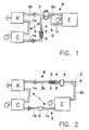
- Air conditioning system B for a vehicle, in particular an automobile has a cooling circuit D on the L in a refrigerant circuit as the drive source a compressor K is provided which has a line section 1a Condenser with refrigerant, from which there is another line section 1b extends to the expansion valve X.
- the line section 1b is downstream of the Expansion valve X continued from a further line section 1c, which in an evaporator E opens.
- a line section extends from the evaporator E. 2a also to the expansion valve X which passes through a line section 2b is extended back to the compressor K.
- the line sections 1a, 1b, 1c lie on the high pressure side, the line sections 2a, 2b, however, on the low pressure side of the refrigerant circuit D.
- line sections 1b, 1c preferably in the line section 1b arranged inside a desiccant batch S, conveniently in one Line section area 3, which has the same inner cross section as the line section 1b, or in an enlarged inner section of the line section 3 '.
- the inner cross section in the area 3, 3 ' can be round, or any have any cross-sectional shape.
- connecting devices in the Line section 1b indicated, for. B. pipe fitting or hose connector ,. which can be used to insert and replace the Exsikkans-Charge S. are. It is conceivable to integrate the line section 1b from the outset Manufacture Exsikkans batch S.
- the position of the desiccans batch S shown in the line section 1b is only for example, the batch S could be at any point on the Line section 1b may be provided, or also in line section 1c. Possible or a position of the Exsikkans batch S at the connection is also expedient of the line section 1b or 1c to the housing, for example the Condenser, the expansion valve X or even the evaporator E.
- the line sections 1b, 1c are light metal or plastic pipes and / or reinforced Plastic hoses (high pressure hydraulic hoses) that are straight and / or run in an arc.
- the Exsikkans batch S could also be in one arcuate region.
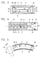
- Fig. 2 relates to another type of air conditioner B with a cooling circuit D in the refrigerant circuit L downstream of the compressor K (expediently a power-controlled compressor or one with a cyclically switching clutch switchable compressor) a capacitor C, downstream of it an orifice O as a flow control device and downstream the aperture O has the evaporator E. Downstream of the evaporator E can be a Accumulator oil separator A may be provided.
- the individual components are switched into the circuit by line sections 1a, 1b, 1c and 2a, 2b, wherein the line sections 1a, 1b, 1c on the high pressure side and the line sections 2a, 2b are on the low pressure side.
- Aperture O is a measuring aperture which is the amount of refrigerant (in liquid state) depending on the sets the respective pressure difference.
- a desiccant batch S inside in line section 2b in an area 3 housed.
- the area 3 of the line section 2b can for example by connecting devices 4 on at least one end for insertion and Removing the batch S can be opened.
- the Exsikkans batch S could too be arranged in the line section 2a, or in an arc of this line section 2a (indicated by dashed lines).
- the refrigerant is on the Low pressure side, i.e. when flowing through the Desikkans batch S essentially gaseous.
- the pipe sections can be made of metallic pipes and / or hoses are formed. With both types of air conditioning shown can also some of the pipe sections of pipes and others of hoses be formed.
- the area 3 in FIG. 2 has the same inner cross section on as the line section 2b. However, it is conceivable, as indicated in FIG. 1, the area 3 'enlarged with respect to the adjacent line section 2b Form internal cross-section.
- Fig. 3 illustrates the placement of the Desikkans batch S in area 3, e.g. in a metallic tube.
- the desiccans for example, is in the form of granules 11 (e.g. a zeolite granulate) in a receptacle 5, which is used as a cartridge, e.g. made of plastic, with several window-like or round passages 6, 7, 8 is trained.
- the passageways are closed with permeable material, see above that the granules 11 cannot fall out. It is convenient to close of the passages uses a plastic filter fabric, which at 9 (Inflow side) a uniform and very small pore size of approx.
- Cartridge 10 must be inserted in the reverse position (with the same flow direction), so that the refrigerant through passage 8 (large pore filter material at 9 ') flows in and out through the passages 7, 6.
- Spacers are arranged at 10 ', which serve to position the cartridge 10 in area 3 and also Ensure all-round inflow of the cartridge 10.
- the seal 12, e.g. at least an O-ring can also be used to position the cartridge 10. It it is also conceivable to slightly push in the wall of area 3 in order to to form a stop for the cartridge.
- Area 3 could also be a section a flexible hose.
- the granulate 11 is expedient in a cage 13 made of any material Plastic, salvaged, with spacers 14 in area 3 (Tube made of plastic or light metal or tube made of reinforced plastic) is positioned. A portion of the refrigerant can bypass the Desiccans Charge S. Downstream of the cage, a fine filter G is secured in position, which consists of a filter fabric 9 with small pore size, e.g. around 50 ⁇ , and with the seal 12 is secured. With regard to the largest possible flow area the fine filter G has a conical shape. It is conceivable to change the fine filter G to another to give shape leading to a large inflow surface. To secure the position of the cage 13 and the fine filter G could depress the wall of the area 3 be (front and rear), or security elements could be used (e.g. Expansion rings).
- the desiccans batch S is in an arcuate area 3, e.g. one Hose made of plastic (or a metal tube) arranged.
- the granules 11 is recovered in a bag 18 which is permeable to the refrigerant and prevents the granules from rinsing out.
- the Charge S forms a flexible unit, able to take part in the bends of area 3.
- Charge S is relatively full fitted in the area 3 and, if necessary, supported by the seal 12, which also prevents refrigerant from bypassing the batch.
- a fine filter (not shown) is provided downstream of the batch S.
- For Positioning the batch S can the wall of area 3, e.g. through a Tension ring 19, be constricted to form a stop shoulder 20.
- Dashed lines indicate that the area 3 up to a connecting device 4 leads with which the line section to a housing 21 or the other Part of the line section 1b is connected.
- the housing 21 is for example the housing of the capacitor C.
- the connecting device 4 can be a Be a pipe or hose connector that is screwed, glued or just through Pressing is hermetically sealed.
- the cartridge 10 or the cage 13 can also be flexible to prevent bends the area 3 or the line section receiving the batch to be able to participate. It is conceivable to carry out several batches of desiccans S immediately to be placed one behind the other or even distributed in the line sections or the granules for forming the batch without taking up immediately between two fill in spaced filter elements in the area 3 or in the respective line section are positioned.
- the line section receiving the Charge S. 1a, 1b, 1c, 2a, 2b, 3, 3 'can in particular with what is enlarged for batch S.
- Internal cross-section, especially with sufficient burst pressure resistance expediently made of long fiber reinforced thermoplastic (trade name: Celstran der Company Hoechst AG) inject or extrude. Examples of such a long fiber reinforced Thermoplastics are polyamide 6.6 or polypropylene 6.6 with 30 - 70% by weight of glass fibers with lengths of approx. 10 mm.
Landscapes
- Engineering & Computer Science (AREA)
- Mechanical Engineering (AREA)
- Physics & Mathematics (AREA)
- Thermal Sciences (AREA)
- Chemical & Material Sciences (AREA)
- General Engineering & Computer Science (AREA)
- Power Engineering (AREA)
- Analytical Chemistry (AREA)
- Ocean & Marine Engineering (AREA)
- Aviation & Aerospace Engineering (AREA)
- Pulmonology (AREA)
- General Health & Medical Sciences (AREA)
- Health & Medical Sciences (AREA)
- Combustion & Propulsion (AREA)
- Air-Conditioning For Vehicles (AREA)
- Central Air Conditioning (AREA)
- Drying Of Gases (AREA)
- Air Filters, Heat-Exchange Apparatuses, And Housings Of Air-Conditioning Units (AREA)
Applications Claiming Priority (2)
| Application Number | Priority Date | Filing Date | Title |
|---|---|---|---|
| DE29705398U DE29705398U1 (de) | 1997-03-25 | 1997-03-25 | Klimaanlage |
| DE29705398U | 1997-03-25 |
Publications (3)
| Publication Number | Publication Date |
|---|---|
| EP0867320A2 true EP0867320A2 (fr) | 1998-09-30 |
| EP0867320A3 EP0867320A3 (fr) | 2000-12-27 |
| EP0867320B1 EP0867320B1 (fr) | 2005-11-16 |
Family
ID=8038019
Family Applications (1)
| Application Number | Title | Priority Date | Filing Date |
|---|---|---|---|
| EP97121767A Revoked EP0867320B1 (fr) | 1997-03-25 | 1997-12-10 | Dispositif de conditionnement d'air |
Country Status (3)
| Country | Link |
|---|---|
| EP (1) | EP0867320B1 (fr) |
| DE (2) | DE29705398U1 (fr) |
| ES (1) | ES2252769T3 (fr) |
Cited By (3)
| Publication number | Priority date | Publication date | Assignee | Title |
|---|---|---|---|---|
| EP1264717A2 (fr) | 2001-06-07 | 2002-12-11 | Eugen Ehs | Ensemble de construction de tuyaux pour conditionneurs d'air et procédé de fabrication de tuyaux |
| EP1342965A1 (fr) * | 2002-03-06 | 2003-09-10 | Stanhope Products Company | Sac de déshydratant et capuchon de filtre associé pour condenseur à réservoir intégré |
| WO2006102862A1 (fr) * | 2005-03-31 | 2006-10-05 | Kenmore Thermo Kälte GmbH | Ensemble deshydrateur installe dans un circuit de refrigerant |
Families Citing this family (3)
| Publication number | Priority date | Publication date | Assignee | Title |
|---|---|---|---|---|
| AR082603A1 (es) | 2011-08-09 | 2012-12-19 | Lavaque Oscar | Un dispositivo solubilizador de dioxido de carbono en una bebida, de presion variable |
| US9815557B2 (en) * | 2012-09-20 | 2017-11-14 | Humbay Health, LLC | Aircraft humidifier |
| US20190283340A1 (en) * | 2018-03-16 | 2019-09-19 | Hamilton Sundstrand Corporation | Oxygen barrier for composites |
Citations (4)
| Publication number | Priority date | Publication date | Assignee | Title |
|---|---|---|---|---|
| DE3606029A1 (de) | 1985-02-25 | 1986-08-28 | Nippondenso Co. Ltd., Kariya, Aichi | Behaelter zum aufnehmen des kuehlmittels eines kuehlkreislaufes |
| DE4018585A1 (de) | 1990-06-09 | 1991-12-12 | Audi Ag | Kaelteanlage insbesondere fuer ein kraftfahrzeug |
| DE4035071A1 (de) | 1990-11-05 | 1992-05-07 | Hansa Metallwerke Ag | Filtertrockner sowie austauschbarer einsatz fuer diesen |
| DE4319293A1 (de) | 1993-06-10 | 1994-12-15 | Behr Gmbh & Co | Klimaanlage für ein Fahrzeug |
Family Cites Families (4)
| Publication number | Priority date | Publication date | Assignee | Title |
|---|---|---|---|---|
| US3175342A (en) * | 1963-01-16 | 1965-03-30 | Parker Hannifin Corp | Filter dryer unit for cleaning sealed refrigerating systems after motor burn outs |
| US4209401A (en) * | 1978-04-20 | 1980-06-24 | Emerson Electric Co. | Filter drier |
| US4255940A (en) * | 1979-08-09 | 1981-03-17 | Parker-Hannifin Corporation | Discharge line filter-dryer |
| US4637881A (en) * | 1983-03-30 | 1987-01-20 | Emerson Electric Co. | Filter drier |
-
1997
- 1997-03-25 DE DE29705398U patent/DE29705398U1/de not_active Expired - Lifetime
- 1997-12-10 DE DE59712487T patent/DE59712487D1/de not_active Revoked
- 1997-12-10 ES ES97121767T patent/ES2252769T3/es not_active Expired - Lifetime
- 1997-12-10 EP EP97121767A patent/EP0867320B1/fr not_active Revoked
Patent Citations (4)
| Publication number | Priority date | Publication date | Assignee | Title |
|---|---|---|---|---|
| DE3606029A1 (de) | 1985-02-25 | 1986-08-28 | Nippondenso Co. Ltd., Kariya, Aichi | Behaelter zum aufnehmen des kuehlmittels eines kuehlkreislaufes |
| DE4018585A1 (de) | 1990-06-09 | 1991-12-12 | Audi Ag | Kaelteanlage insbesondere fuer ein kraftfahrzeug |
| DE4035071A1 (de) | 1990-11-05 | 1992-05-07 | Hansa Metallwerke Ag | Filtertrockner sowie austauschbarer einsatz fuer diesen |
| DE4319293A1 (de) | 1993-06-10 | 1994-12-15 | Behr Gmbh & Co | Klimaanlage für ein Fahrzeug |
Cited By (3)
| Publication number | Priority date | Publication date | Assignee | Title |
|---|---|---|---|---|
| EP1264717A2 (fr) | 2001-06-07 | 2002-12-11 | Eugen Ehs | Ensemble de construction de tuyaux pour conditionneurs d'air et procédé de fabrication de tuyaux |
| EP1342965A1 (fr) * | 2002-03-06 | 2003-09-10 | Stanhope Products Company | Sac de déshydratant et capuchon de filtre associé pour condenseur à réservoir intégré |
| WO2006102862A1 (fr) * | 2005-03-31 | 2006-10-05 | Kenmore Thermo Kälte GmbH | Ensemble deshydrateur installe dans un circuit de refrigerant |
Also Published As
| Publication number | Publication date |
|---|---|
| DE29705398U1 (de) | 1997-05-22 |
| ES2252769T3 (es) | 2006-05-16 |
| EP0867320B1 (fr) | 2005-11-16 |
| EP0867320A3 (fr) | 2000-12-27 |
| DE59712487D1 (de) | 2005-12-22 |
Similar Documents
| Publication | Publication Date | Title |
|---|---|---|
| EP0669506B2 (fr) | Condenseur pour une installation de climatisation d'un véhicule | |
| DE69907820T2 (de) | Behälter für kraftstofftank und kraftstofftank mit einem solchen behälter | |
| DE3017851C2 (de) | Filteranordnung | |
| DE112005001921B4 (de) | Verschluß zum hermetischen Abdichten eines Trocknerbehälters | |
| EP1147930B1 (fr) | Condenseur pour la climatisation de véhicule automobile | |
| DE69203373T2 (de) | In-line-Filtereinrichtung mit Nebelfilter und Luftsammler. | |
| DE4141823A1 (de) | Fluessigkeitsfilter | |
| DE69508186T2 (de) | Fahrzeuggasfühler | |
| DE4319293A1 (de) | Klimaanlage für ein Fahrzeug | |
| DE20012736U1 (de) | Baugruppe für eine Brennkraftmaschine mit einem Ölfilter | |
| DE3731507A1 (de) | Filtereinrichtung | |
| DE10009864A1 (de) | Kühlvorrichtung | |
| EP1246680B1 (fr) | Dispositif filtrant | |
| DE102005005187A1 (de) | Kondensator für eine Klimaanlage, insbesondere eines Kraftfahrzeuges | |
| EP1492985A1 (fr) | Condenseur a fluide frigorigene | |
| DE69516940T2 (de) | Sammler für eine Klimaanlage | |
| DE19524668C2 (de) | Einfassung eines Heizungswärmetauschers für Kraftfahrzeuge | |
| DE102018119220B3 (de) | Filterelement zur Filtration und Entfeuchtung eines Gases und Filtereinrichtung | |
| EP1682830A2 (fr) | Echangeur thermique et ensemble collecteur-dessiccateur pour echangeur thermique | |
| EP0867320B1 (fr) | Dispositif de conditionnement d'air | |
| DE69801531T2 (de) | Fahrzeug-Klimaanlage und Trocknerpatrone für eine Fahrzeug-Klimaanlage | |
| EP0341345A1 (fr) | Vanne avec filtre intégré | |
| EP1522804A1 (fr) | Dispositif de fixation d'agent déshydratant dans un condenseur et condenseur | |
| DE10249110B4 (de) | Filtereinrichtung, Filterelement und Filterrahmen | |
| DE102004059680B4 (de) | Bauanordnung für Einrichtungen zum Austausch von Wärme |
Legal Events
| Date | Code | Title | Description |
|---|---|---|---|
| PUAI | Public reference made under article 153(3) epc to a published international application that has entered the european phase |
Free format text: ORIGINAL CODE: 0009012 |
|
| AK | Designated contracting states |
Kind code of ref document: A2 Designated state(s): DE ES FR GB IT SE |
|
| AX | Request for extension of the european patent |
Free format text: AL;LT;LV;MK;RO;SI |
|
| PUAL | Search report despatched |
Free format text: ORIGINAL CODE: 0009013 |
|
| AK | Designated contracting states |
Kind code of ref document: A3 Designated state(s): AT BE CH DE DK ES FI FR GB GR IE IT LI LU MC NL PT SE |
|
| AX | Request for extension of the european patent |
Free format text: AL;LT;LV;MK;RO;SI |
|
| RIC1 | Information provided on ipc code assigned before grant |
Free format text: 7B 60H 1/32 A, 7F 25B 43/00 B |
|
| 17P | Request for examination filed |
Effective date: 20010531 |
|
| AKX | Designation fees paid |
Free format text: DE ES FR GB IT SE |
|
| RTI1 | Title (correction) |
Free format text: AIR CONDITIONING DEVICE |
|
| 17Q | First examination report despatched |
Effective date: 20040924 |
|
| GRAP | Despatch of communication of intention to grant a patent |
Free format text: ORIGINAL CODE: EPIDOSNIGR1 |
|
| GRAS | Grant fee paid |
Free format text: ORIGINAL CODE: EPIDOSNIGR3 |
|
| GRAA | (expected) grant |
Free format text: ORIGINAL CODE: 0009210 |
|
| AK | Designated contracting states |
Kind code of ref document: B1 Designated state(s): DE ES FR GB IT SE |
|
| REG | Reference to a national code |
Ref country code: GB Ref legal event code: FG4D Free format text: NOT ENGLISH |
|
| GBT | Gb: translation of ep patent filed (gb section 77(6)(a)/1977) | ||
| REF | Corresponds to: |
Ref document number: 59712487 Country of ref document: DE Date of ref document: 20051222 Kind code of ref document: P |
|
| REG | Reference to a national code |
Ref country code: SE Ref legal event code: TRGR |
|
| REG | Reference to a national code |
Ref country code: ES Ref legal event code: FG2A Ref document number: 2252769 Country of ref document: ES Kind code of ref document: T3 |
|
| ET | Fr: translation filed | ||
| PLBI | Opposition filed |
Free format text: ORIGINAL CODE: 0009260 |
|
| PLAX | Notice of opposition and request to file observation + time limit sent |
Free format text: ORIGINAL CODE: EPIDOSNOBS2 |
|
| 26 | Opposition filed |
Opponent name: BEHR GMBH & CO. KG Effective date: 20060816 |
|
| PGFP | Annual fee paid to national office [announced via postgrant information from national office to epo] |
Ref country code: SE Payment date: 20061215 Year of fee payment: 10 |
|
| PLAF | Information modified related to communication of a notice of opposition and request to file observations + time limit |
Free format text: ORIGINAL CODE: EPIDOSCOBS2 |
|
| PLAF | Information modified related to communication of a notice of opposition and request to file observations + time limit |
Free format text: ORIGINAL CODE: EPIDOSCOBS2 |
|
| PLAF | Information modified related to communication of a notice of opposition and request to file observations + time limit |
Free format text: ORIGINAL CODE: EPIDOSCOBS2 |
|
| PLBB | Reply of patent proprietor to notice(s) of opposition received |
Free format text: ORIGINAL CODE: EPIDOSNOBS3 |
|
| PLAY | Examination report in opposition despatched + time limit |
Free format text: ORIGINAL CODE: EPIDOSNORE2 |
|
| PLAB | Opposition data, opponent's data or that of the opponent's representative modified |
Free format text: ORIGINAL CODE: 0009299OPPO |
|
| EUG | Se: european patent has lapsed | ||
| PLAH | Information related to despatch of examination report in opposition + time limit modified |
Free format text: ORIGINAL CODE: EPIDOSCORE2 |
|
| PG25 | Lapsed in a contracting state [announced via postgrant information from national office to epo] |
Ref country code: SE Free format text: LAPSE BECAUSE OF NON-PAYMENT OF DUE FEES Effective date: 20071211 |
|
| PLBC | Reply to examination report in opposition received |
Free format text: ORIGINAL CODE: EPIDOSNORE3 |
|
| PGFP | Annual fee paid to national office [announced via postgrant information from national office to epo] |
Ref country code: ES Payment date: 20081215 Year of fee payment: 12 |
|
| PGFP | Annual fee paid to national office [announced via postgrant information from national office to epo] |
Ref country code: IT Payment date: 20081219 Year of fee payment: 12 |
|
| PGFP | Annual fee paid to national office [announced via postgrant information from national office to epo] |
Ref country code: FR Payment date: 20081211 Year of fee payment: 12 |
|
| PGFP | Annual fee paid to national office [announced via postgrant information from national office to epo] |
Ref country code: DE Payment date: 20090129 Year of fee payment: 12 |
|
| PGFP | Annual fee paid to national office [announced via postgrant information from national office to epo] |
Ref country code: GB Payment date: 20081217 Year of fee payment: 12 |
|
| RDAF | Communication despatched that patent is revoked |
Free format text: ORIGINAL CODE: EPIDOSNREV1 |
|
| RDAG | Patent revoked |
Free format text: ORIGINAL CODE: 0009271 |
|
| STAA | Information on the status of an ep patent application or granted ep patent |
Free format text: STATUS: PATENT REVOKED |
|
| 27W | Patent revoked |
Effective date: 20090713 |
|
| GBPR | Gb: patent revoked under art. 102 of the ep convention designating the uk as contracting state |
Effective date: 20090713 |