EP0867324A2 - Véhicule, notamment un chariot élévateur, entrainé par un moteur électrique dont le rotor et le stator tournent en sens opposé - Google Patents
Véhicule, notamment un chariot élévateur, entrainé par un moteur électrique dont le rotor et le stator tournent en sens opposé Download PDFInfo
- Publication number
- EP0867324A2 EP0867324A2 EP98200658A EP98200658A EP0867324A2 EP 0867324 A2 EP0867324 A2 EP 0867324A2 EP 98200658 A EP98200658 A EP 98200658A EP 98200658 A EP98200658 A EP 98200658A EP 0867324 A2 EP0867324 A2 EP 0867324A2
- Authority
- EP
- European Patent Office
- Prior art keywords
- wheel
- stator
- rotor
- shaft
- electric motor
- Prior art date
- Legal status (The legal status is an assumption and is not a legal conclusion. Google has not performed a legal analysis and makes no representation as to the accuracy of the status listed.)
- Granted
Links
Images

Classifications
-
- B—PERFORMING OPERATIONS; TRANSPORTING
- B60—VEHICLES IN GENERAL
- B60K—ARRANGEMENT OR MOUNTING OF PROPULSION UNITS OR OF TRANSMISSIONS IN VEHICLES; ARRANGEMENT OR MOUNTING OF PLURAL DIVERSE PRIME-MOVERS IN VEHICLES; AUXILIARY DRIVES FOR VEHICLES; INSTRUMENTATION OR DASHBOARDS FOR VEHICLES; ARRANGEMENTS IN CONNECTION WITH COOLING, AIR INTAKE, GAS EXHAUST OR FUEL SUPPLY OF PROPULSION UNITS IN VEHICLES
- B60K17/00—Arrangement or mounting of transmissions in vehicles
- B60K17/04—Arrangement or mounting of transmissions in vehicles characterised by arrangement, location or kind of gearing
- B60K17/043—Transmission unit disposed in on near the vehicle wheel, or between the differential gear unit and the wheel
-
- B—PERFORMING OPERATIONS; TRANSPORTING
- B60—VEHICLES IN GENERAL
- B60K—ARRANGEMENT OR MOUNTING OF PROPULSION UNITS OR OF TRANSMISSIONS IN VEHICLES; ARRANGEMENT OR MOUNTING OF PLURAL DIVERSE PRIME-MOVERS IN VEHICLES; AUXILIARY DRIVES FOR VEHICLES; INSTRUMENTATION OR DASHBOARDS FOR VEHICLES; ARRANGEMENTS IN CONNECTION WITH COOLING, AIR INTAKE, GAS EXHAUST OR FUEL SUPPLY OF PROPULSION UNITS IN VEHICLES
- B60K1/00—Arrangement or mounting of electrical propulsion units
- B60K2001/001—Arrangement or mounting of electrical propulsion units one motor mounted on a propulsion axle for rotating right and left wheels of this axle
-
- B—PERFORMING OPERATIONS; TRANSPORTING
- B60—VEHICLES IN GENERAL
- B60Y—INDEXING SCHEME RELATING TO ASPECTS CROSS-CUTTING VEHICLE TECHNOLOGY
- B60Y2200/00—Type of vehicle
- B60Y2200/10—Road Vehicles
- B60Y2200/15—Fork lift trucks, Industrial trucks
Definitions
- the present invention relates to a vehicle, in particular a lift truck, with driving wheels actuated by an electric motor, the stator of which rotates with respect to the fixed frame of the vehicle and is connected to one of the two driving wheels of the same axle and the rotor of which is connected to the other driving wheel of the said axle.
- vehicles called lift trucks which vehicles may have three wheels, two of which are on the same axle and one of which forms a driving wheel, or four wheels arranged in pairs on two axles, one of which is a driving pair.
- the technical problem which is posed, therefore, is that of providing a vehicle, in particular a lift truck, equipped with an apparatus for actuating the driving wheels, which enables the aforementioned drawbacks to be overcome and which provides a greater efficiency compared to both the single motor/differential solution and the twin-motor solution.
- said apparatus should have a simple design, ensure precision and reliability of control, not require complicated synchronisation devices and be able to be applied, without difficulty, to commercial vehicles as well.
- a vehicle in particular a lift truck, comprising a frame and at least one driving axle, at each end of which a wheel is mounted, in which said axle is formed by an electric motor, the stator of which is connected to one of the two wheels mounted on the axle itself and the rotor of which is connected to the other of said wheels, it also being envisaged that said stator is supported by bearings integral with the frame of the vehicle with respect to which the stator rotates.
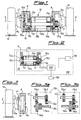
- each driving wheel 1a and 1b of the lift truck according to the invention is mounted on a hub which is schematically shown with the axle 2 and supported by a reduction unit 3, in a manner known per se and therefore not described in detail, housed inside a casing 4a integral with a fixed supporting frame 4.
- the apparatus 10 for actuating the wheels 1a, 1b is located between the two opposite reduction units and is connected, in turn, to the control and regulating devices 100 schematically shown in Figure 2.
- the apparatus according to the invention essentially consists of a direct-current electric motor 10, comprising a stator 10a supported, via bearings 11a, by the fixed support 4 and rotating with respect to the latter.
- the stator 10a has, extending externally from it, a coaxial spindle 10d connected to the reduction unit 3 actuating one, 1b, of the two driving wheels of the truck, which therefore rotates in the same direction as the stator 10a.
- the stator 10a supports, in turn, via bearings 13, the coaxial shaft 10c onto which the rotor 10b is keyed.
- Said shaft 10c extends outside the rotor 10b towards the other driving wheel 1a and is connected to the associated reduction unit 3 by a device 16 for reversing the direction of rotation.
- Said device 16 comprises a first toothed wheel 16a mounted on the shaft 10c, and a second gear 16b mounted on the input shaft 17 of the said reduction unit 3.
- the means 100 for controlling and regulating the motor 10 comprise a battery 110 and a current regulator 120 operated by the accelerator 130 of the truck.
- the rotor 10b is made to rotate by the direct-current supply from the brushes 15b which are supplied by means of the brushes 15a of the stator 10a which receive current from the regulator 120.
- the device 116 for reversing the direction of rotation of the wheel 1a comprises: a pair of coaxial gears 116a, 116b, mounted on the shaft 10c and movable in translation thereon between two opposite positions; an idle wheel 116c, in turn engaged with a third wheel 116d mounted on the input shaft 17 into the reduction unit 3, which shaft also has, mounted on it, an additional toothed wheel 116e located at a certain distance from the said wheel 116d.
- the translation, in either direction, of the toothed wheels 116 on the shaft 10c causes in one case (Fig. 3a) direct engagement of the wheel 116b of the rotor shaft 10c with the wheel 116e of the input shaft 17 into the reduction unit 3 and therefore a configuration in which the wheel 1a rotates in the same direction as the wheel 1b.
- the actuating apparatus may be designed as an alternative embodiment which involves essentially replacement of the direct-current motor 10 with an alternating-current motor 1010.
- the housing of the motor is integral with a casing forming the stator 1010a from which the shaft 10d emerges.
- the stator 1010a is made to rotate by the brushes 15b which receive current via a variable-frequency alternating-current generator 1120 supplied by the battery 1110.
- the rotor 1010b supports the shaft 10c for connection to the driving wheel.
- means 16 are provided for reversing the direction of rotation of the input shaft into the reduction unit of one, 1a, of the two driving wheels.
- Figure 6a illustrates a further embodiment of a device 1116 for obtaining the rotation of the two driving wheels in opposite directions.
- Said device comprises two toothed wheels 1116a and 1116b which are mounted fixed onto the shaft 10c together with a coupling 1130 arranged between the wheels themselves.
- the actuation of the said coupling 1130 in either direction therefore causes the rotation of the wheel 1116a or of the wheel 1116b with consequent transmission of the movement via the wheel 116c or 1116e and therefore the rotation of the wheel 1a with respect to the wheel 1b in the same direction or in opposite directions.
- a lift truck equipped with actuating apparatus is able to achieve all the advantages of the actuating movements of a single motor, but without the disadvantages resulting from the presence of the differential, the function of which is performed by the combined action of the stator and the rotor which, rotating with an adjustable differential speed, perform the same function without loss of efficiency. It is also obvious that many variations may be introduced by the person skilled in the art as regards the choice of the parts which make up the actuating and control apparatus. In the case of actuation with an a.c. motor, special motors with a high starting torque designed to provide the necessary performance characteristics may be used.
- a clutch may be arranged between the rotor/stator shaft and the corresponding wheel, so that the clutch itself is normally disengaged so as to allow normal start-up of the truck.
- the engagement of the clutch allows the motor to run under no-load conditions so that, when the clutch is disengaged, the inertia of the motor is used in order to increase the starting torque of the truck.
Landscapes
- Engineering & Computer Science (AREA)
- Chemical & Material Sciences (AREA)
- Combustion & Propulsion (AREA)
- Transportation (AREA)
- Mechanical Engineering (AREA)
- Electric Propulsion And Braking For Vehicles (AREA)
- Forklifts And Lifting Vehicles (AREA)
- Arrangement Or Mounting Of Propulsion Units For Vehicles (AREA)
- Vehicle Body Suspensions (AREA)
- Connection Of Motors, Electrical Generators, Mechanical Devices, And The Like (AREA)
Applications Claiming Priority (2)
| Application Number | Priority Date | Filing Date | Title |
|---|---|---|---|
| ITMI970686 | 1997-03-25 | ||
| IT97MI000686A IT1290820B1 (it) | 1997-03-25 | 1997-03-25 | Veicolo particolarmente carrello elevatore azionato da un motore elettrico con statore e rotore controrotanti |
Publications (3)
| Publication Number | Publication Date |
|---|---|
| EP0867324A2 true EP0867324A2 (fr) | 1998-09-30 |
| EP0867324A3 EP0867324A3 (fr) | 1999-06-23 |
| EP0867324B1 EP0867324B1 (fr) | 2003-05-21 |
Family
ID=11376600
Family Applications (1)
| Application Number | Title | Priority Date | Filing Date |
|---|---|---|---|
| EP98200658A Expired - Lifetime EP0867324B1 (fr) | 1997-03-25 | 1998-03-04 | Véhicule, notamment un chariot élévateur, entrainé par un moteur électrique dont le rotor et le stator tournent en sens opposé |
Country Status (6)
| Country | Link |
|---|---|
| EP (1) | EP0867324B1 (fr) |
| AT (1) | ATE240851T1 (fr) |
| DE (1) | DE69814720T2 (fr) |
| DK (1) | DK0867324T3 (fr) |
| ES (1) | ES2195267T3 (fr) |
| IT (1) | IT1290820B1 (fr) |
Cited By (5)
| Publication number | Priority date | Publication date | Assignee | Title |
|---|---|---|---|---|
| WO1999036286A1 (fr) * | 1998-01-16 | 1999-07-22 | Oskar Wachauer | Systeme d'entrainement pour vehicule, notamment pour vehicule electrique a ecartement variable des roues |
| WO2001056138A1 (fr) * | 2000-01-28 | 2001-08-02 | Oskar Wachauer | Dispositif d'entrainement electrique pour un vehicule |
| EP1798095A3 (fr) * | 2003-07-02 | 2009-09-16 | Zf Friedrichshafen Ag | Essieu surbaissé |
| ITAN20090075A1 (it) * | 2009-10-08 | 2011-04-09 | Nuova Maip Macchine Agric | Veicolo automobilistico con motore elettrico. |
| EP2641319A4 (fr) * | 2010-11-15 | 2018-04-18 | BAE Systems Hägglunds Aktiebolag | Dispositif de propulsion électrique |
Families Citing this family (2)
| Publication number | Priority date | Publication date | Assignee | Title |
|---|---|---|---|---|
| DE102009006424A1 (de) | 2009-01-21 | 2010-07-22 | Dr. Ing. H.C. F. Porsche Aktiengesellschaft | Antriebsachse |
| DE102010043901A1 (de) * | 2010-11-15 | 2012-05-16 | Bayerische Motoren Werke Aktiengesellschaft | Elektrisch angetriebene Achse eines zweispurigen Fahrzeugs |
Family Cites Families (5)
| Publication number | Priority date | Publication date | Assignee | Title |
|---|---|---|---|---|
| US3267311A (en) * | 1963-08-19 | 1966-08-16 | Henry C Lamparty | Combination electric motor and differential drive for vehicles |
| IT952995B (it) * | 1972-03-16 | 1973-07-30 | Salvadorini R | Autoveicolo a propulsione termoelettrica |
| US4130172A (en) * | 1975-06-20 | 1978-12-19 | Moody Warren E | Electric vehicle |
| JPS5245009A (en) * | 1975-10-06 | 1977-04-08 | Ekutasu Syst Kk | Prime mover |
| JPH0698408A (ja) * | 1992-09-11 | 1994-04-08 | Fuji Electric Co Ltd | 電気自動車の駆動システム |
-
1997
- 1997-03-25 IT IT97MI000686A patent/IT1290820B1/it active IP Right Grant
-
1998
- 1998-03-04 ES ES98200658T patent/ES2195267T3/es not_active Expired - Lifetime
- 1998-03-04 DK DK98200658T patent/DK0867324T3/da active
- 1998-03-04 DE DE69814720T patent/DE69814720T2/de not_active Expired - Lifetime
- 1998-03-04 AT AT98200658T patent/ATE240851T1/de active
- 1998-03-04 EP EP98200658A patent/EP0867324B1/fr not_active Expired - Lifetime
Non-Patent Citations (1)
| Title |
|---|
| None |
Cited By (10)
| Publication number | Priority date | Publication date | Assignee | Title |
|---|---|---|---|---|
| WO1999036286A1 (fr) * | 1998-01-16 | 1999-07-22 | Oskar Wachauer | Systeme d'entrainement pour vehicule, notamment pour vehicule electrique a ecartement variable des roues |
| WO2001056138A1 (fr) * | 2000-01-28 | 2001-08-02 | Oskar Wachauer | Dispositif d'entrainement electrique pour un vehicule |
| AT408210B (de) * | 2000-01-28 | 2001-09-25 | Wachauer Oskar | Elektrischer antrieb für ein fahrzeug |
| US6749532B2 (en) | 2000-01-28 | 2004-06-15 | Oskar Wachauer | Electric drive for a vehicle |
| EP1798095A3 (fr) * | 2003-07-02 | 2009-09-16 | Zf Friedrichshafen Ag | Essieu surbaissé |
| ITAN20090075A1 (it) * | 2009-10-08 | 2011-04-09 | Nuova Maip Macchine Agric | Veicolo automobilistico con motore elettrico. |
| WO2011042317A1 (fr) * | 2009-10-08 | 2011-04-14 | Pieralisi Maip Societa' Per Azioni | Véhicule motorisé pourvu d'un moteur électrique |
| JP2013507286A (ja) * | 2009-10-08 | 2013-03-04 | ピエラリシ マイプ ソチエタ’ ペル アツィオーニ | 電動モータを備えた自動車 |
| US8844659B2 (en) | 2009-10-08 | 2014-09-30 | Pieralisi Maip Societa' Per Azioni | Motor vehicle with electric motor |
| EP2641319A4 (fr) * | 2010-11-15 | 2018-04-18 | BAE Systems Hägglunds Aktiebolag | Dispositif de propulsion électrique |
Also Published As
| Publication number | Publication date |
|---|---|
| ATE240851T1 (de) | 2003-06-15 |
| DE69814720T2 (de) | 2003-11-20 |
| EP0867324A3 (fr) | 1999-06-23 |
| EP0867324B1 (fr) | 2003-05-21 |
| ES2195267T3 (es) | 2003-12-01 |
| IT1290820B1 (it) | 1998-12-11 |
| DK0867324T3 (da) | 2003-09-15 |
| DE69814720D1 (de) | 2003-06-26 |
| ITMI970686A1 (it) | 1998-09-25 |
Similar Documents
| Publication | Publication Date | Title |
|---|---|---|
| JP7327614B2 (ja) | 車両用駆動装置 | |
| EP3936358B1 (fr) | Système de commande de moteur électrique double | |
| JP4693327B2 (ja) | 車両用電気駆動装置 | |
| US9011285B2 (en) | Drive arrangement | |
| JP4280416B2 (ja) | 車両用の駆動部 | |
| US5487438A (en) | Driving system for an electric vehicle | |
| JP2006112474A (ja) | 差動装置およびこれを用いた車両の駆動力伝達ユニット | |
| EP2485909B1 (fr) | Véhicule automobile à propulsion électrique | |
| JP2025188089A5 (fr) | ||
| EP0867324B1 (fr) | Véhicule, notamment un chariot élévateur, entrainé par un moteur électrique dont le rotor et le stator tournent en sens opposé | |
| CN119585131A (zh) | 紧凑型电动轴组件 | |
| JPH0680036A (ja) | 電気自動車の4輪駆動方法 | |
| WO2023054363A1 (fr) | Dispositif d'entraînement pour véhicule | |
| EP1461222B1 (fr) | Moteur electrique a rotor couple a l'element destine a etre mis en rotation | |
| CN212708905U (zh) | 一种双电机驱动系统 | |
| JP4150567B2 (ja) | 車両用駆動装置の組み立て方法 | |
| JP2019084905A (ja) | 車両用動力伝達装置 | |
| JP7634316B1 (ja) | 車輪回転制御装置及び車輪回転制御装置を備えた車両 | |
| JPH1189178A (ja) | 電気自動車用インホィールモータ | |
| US12377719B2 (en) | Drive device for a drive shaft comprising two rotating machines | |
| CN223314824U (zh) | 驱动装置及车辆 | |
| JP2001039174A (ja) | 電動機の出力ドライブユニット | |
| CN118544785A (zh) | 电驱动系统及具有其的车辆 | |
| JPH06105516A (ja) | 電気自動車駆動装置 | |
| JP2018112221A (ja) | 動力装置 |
Legal Events
| Date | Code | Title | Description |
|---|---|---|---|
| PUAI | Public reference made under article 153(3) epc to a published international application that has entered the european phase |
Free format text: ORIGINAL CODE: 0009012 |
|
| AK | Designated contracting states |
Kind code of ref document: A2 Designated state(s): AT CH DE DK ES FR GB GR IT LI SE |
|
| AX | Request for extension of the european patent |
Free format text: AL;LT;LV;MK;RO;SI |
|
| PUAL | Search report despatched |
Free format text: ORIGINAL CODE: 0009013 |
|
| AK | Designated contracting states |
Kind code of ref document: A3 Designated state(s): AT BE CH DE DK ES FI FR GB GR IE IT LI LU MC NL PT SE |
|
| AX | Request for extension of the european patent |
Free format text: AL;LT;LV;MK;RO;SI |
|
| 17P | Request for examination filed |
Effective date: 19991209 |
|
| AKX | Designation fees paid |
Free format text: AT CH DE DK ES FR GB GR IT LI SE |
|
| 17Q | First examination report despatched |
Effective date: 20011018 |
|
| GRAH | Despatch of communication of intention to grant a patent |
Free format text: ORIGINAL CODE: EPIDOS IGRA |
|
| GRAH | Despatch of communication of intention to grant a patent |
Free format text: ORIGINAL CODE: EPIDOS IGRA |
|
| RAP1 | Party data changed (applicant data changed or rights of an application transferred) |
Owner name: NUOVA M.A.I.P.,MACCHINE AGRICOLE INDUSTRIALI PIERA |
|
| GRAA | (expected) grant |
Free format text: ORIGINAL CODE: 0009210 |
|
| AK | Designated contracting states |
Designated state(s): AT CH DE DK ES FR GB GR IT LI SE |
|
| REG | Reference to a national code |
Ref country code: GB Ref legal event code: FG4D |
|
| REG | Reference to a national code |
Ref country code: CH Ref legal event code: NV Representative=s name: DR. LUSUARDI AG Ref country code: CH Ref legal event code: EP |
|
| REF | Corresponds to: |
Ref document number: 69814720 Country of ref document: DE Date of ref document: 20030626 Kind code of ref document: P |
|
| REG | Reference to a national code |
Ref country code: SE Ref legal event code: TRGR |
|
| REG | Reference to a national code |
Ref country code: DK Ref legal event code: T3 |
|
| REG | Reference to a national code |
Ref country code: GR Ref legal event code: EP Ref document number: 20030403240 Country of ref document: GR |
|
| ET | Fr: translation filed | ||
| PLBE | No opposition filed within time limit |
Free format text: ORIGINAL CODE: 0009261 |
|
| STAA | Information on the status of an ep patent application or granted ep patent |
Free format text: STATUS: NO OPPOSITION FILED WITHIN TIME LIMIT |
|
| 26N | No opposition filed |
Effective date: 20040224 |
|
| PGFP | Annual fee paid to national office [announced via postgrant information from national office to epo] |
Ref country code: AT Payment date: 20110331 Year of fee payment: 14 |
|
| PGFP | Annual fee paid to national office [announced via postgrant information from national office to epo] |
Ref country code: GR Payment date: 20110331 Year of fee payment: 14 |
|
| PGFP | Annual fee paid to national office [announced via postgrant information from national office to epo] |
Ref country code: DE Payment date: 20110427 Year of fee payment: 14 Ref country code: CH Payment date: 20110330 Year of fee payment: 14 Ref country code: SE Payment date: 20110331 Year of fee payment: 14 Ref country code: GB Payment date: 20110330 Year of fee payment: 14 Ref country code: FR Payment date: 20110414 Year of fee payment: 14 Ref country code: ES Payment date: 20110331 Year of fee payment: 14 |
|
| PGFP | Annual fee paid to national office [announced via postgrant information from national office to epo] |
Ref country code: IT Payment date: 20110330 Year of fee payment: 14 |
|
| PGFP | Annual fee paid to national office [announced via postgrant information from national office to epo] |
Ref country code: DK Payment date: 20120312 Year of fee payment: 15 |
|
| REG | Reference to a national code |
Ref country code: SE Ref legal event code: EUG |
|
| PG25 | Lapsed in a contracting state [announced via postgrant information from national office to epo] |
Ref country code: SE Free format text: LAPSE BECAUSE OF NON-PAYMENT OF DUE FEES Effective date: 20120305 |
|
| REG | Reference to a national code |
Ref country code: CH Ref legal event code: PL |
|
| GBPC | Gb: european patent ceased through non-payment of renewal fee |
Effective date: 20120304 |
|
| REG | Reference to a national code |
Ref country code: GR Ref legal event code: ML Ref document number: 20030403240 Country of ref document: GR Effective date: 20121008 |
|
| REG | Reference to a national code |
Ref country code: AT Ref legal event code: MM01 Ref document number: 240851 Country of ref document: AT Kind code of ref document: T Effective date: 20120304 |
|
| REG | Reference to a national code |
Ref country code: FR Ref legal event code: ST Effective date: 20121130 |
|
| PG25 | Lapsed in a contracting state [announced via postgrant information from national office to epo] |
Ref country code: FR Free format text: LAPSE BECAUSE OF NON-PAYMENT OF DUE FEES Effective date: 20120402 Ref country code: LI Free format text: LAPSE BECAUSE OF NON-PAYMENT OF DUE FEES Effective date: 20120331 Ref country code: AT Free format text: LAPSE BECAUSE OF NON-PAYMENT OF DUE FEES Effective date: 20120304 Ref country code: GB Free format text: LAPSE BECAUSE OF NON-PAYMENT OF DUE FEES Effective date: 20120304 Ref country code: CH Free format text: LAPSE BECAUSE OF NON-PAYMENT OF DUE FEES Effective date: 20120331 |
|
| REG | Reference to a national code |
Ref country code: DE Ref legal event code: R119 Ref document number: 69814720 Country of ref document: DE Effective date: 20121002 |
|
| PG25 | Lapsed in a contracting state [announced via postgrant information from national office to epo] |
Ref country code: IT Free format text: LAPSE BECAUSE OF NON-PAYMENT OF DUE FEES Effective date: 20120304 Ref country code: GR Free format text: LAPSE BECAUSE OF NON-PAYMENT OF DUE FEES Effective date: 20121008 |
|
| REG | Reference to a national code |
Ref country code: ES Ref legal event code: FD2A Effective date: 20130710 |
|
| PG25 | Lapsed in a contracting state [announced via postgrant information from national office to epo] |
Ref country code: ES Free format text: LAPSE BECAUSE OF NON-PAYMENT OF DUE FEES Effective date: 20120305 |
|
| REG | Reference to a national code |
Ref country code: DK Ref legal event code: EBP Effective date: 20130331 Ref country code: DK Ref legal event code: EBP |
|
| PG25 | Lapsed in a contracting state [announced via postgrant information from national office to epo] |
Ref country code: DK Free format text: LAPSE BECAUSE OF NON-PAYMENT OF DUE FEES Effective date: 20130331 |
|
| PG25 | Lapsed in a contracting state [announced via postgrant information from national office to epo] |
Ref country code: DE Free format text: LAPSE BECAUSE OF NON-PAYMENT OF DUE FEES Effective date: 20121002 |