EP0867594A1 - Automatische Bremsvorrichtung für einen Elektromotor, der ein drehendes Teil antreibt - Google Patents
Automatische Bremsvorrichtung für einen Elektromotor, der ein drehendes Teil antreibt Download PDFInfo
- Publication number
- EP0867594A1 EP0867594A1 EP98810159A EP98810159A EP0867594A1 EP 0867594 A1 EP0867594 A1 EP 0867594A1 EP 98810159 A EP98810159 A EP 98810159A EP 98810159 A EP98810159 A EP 98810159A EP 0867594 A1 EP0867594 A1 EP 0867594A1
- Authority
- EP
- European Patent Office
- Prior art keywords
- switch
- finger
- support
- stop device
- mobile
- Prior art date
- Legal status (The legal status is an assumption and is not a legal conclusion. Google has not performed a legal analysis and makes no representation as to the accuracy of the status listed.)
- Withdrawn
Links
- 230000004044 response Effects 0.000 claims abstract description 5
- 238000004804 winding Methods 0.000 claims description 33
- 230000008878 coupling Effects 0.000 claims description 25
- 238000010168 coupling process Methods 0.000 claims description 25
- 238000005859 coupling reaction Methods 0.000 claims description 25
- 230000000694 effects Effects 0.000 claims description 11
- 238000006073 displacement reaction Methods 0.000 claims description 7
- 230000006835 compression Effects 0.000 claims description 3
- 238000007906 compression Methods 0.000 claims description 3
- 238000009825 accumulation Methods 0.000 claims 1
- 238000005086 pumping Methods 0.000 claims 1
- 238000007789 sealing Methods 0.000 claims 1
- 230000009466 transformation Effects 0.000 claims 1
- 230000001131 transforming effect Effects 0.000 claims 1
- 230000007246 mechanism Effects 0.000 abstract description 3
- 230000009471 action Effects 0.000 abstract description 2
- 238000005096 rolling process Methods 0.000 description 5
- 238000001514 detection method Methods 0.000 description 3
- YSSSPARMOAYJTE-UHFFFAOYSA-N dibenzo-18-crown-6 Chemical compound O1CCOCCOC2=CC=CC=C2OCCOCCOC2=CC=CC=C21 YSSSPARMOAYJTE-UHFFFAOYSA-N 0.000 description 2
- 230000004048 modification Effects 0.000 description 2
- 238000012986 modification Methods 0.000 description 2
- 230000007935 neutral effect Effects 0.000 description 2
- 238000012550 audit Methods 0.000 description 1
- 230000005284 excitation Effects 0.000 description 1
- 230000005294 ferromagnetic effect Effects 0.000 description 1
- 238000009434 installation Methods 0.000 description 1
- 230000005291 magnetic effect Effects 0.000 description 1
- 238000005259 measurement Methods 0.000 description 1
- 210000000056 organ Anatomy 0.000 description 1
- 230000000149 penetrating effect Effects 0.000 description 1
- 230000009467 reduction Effects 0.000 description 1
- 230000000717 retained effect Effects 0.000 description 1
- 238000009785 tube rolling Methods 0.000 description 1
- 230000002747 voluntary effect Effects 0.000 description 1
Images


Classifications
-
- E—FIXED CONSTRUCTIONS
- E06—DOORS, WINDOWS, SHUTTERS, OR ROLLER BLINDS IN GENERAL; LADDERS
- E06B—FIXED OR MOVABLE CLOSURES FOR OPENINGS IN BUILDINGS, VEHICLES, FENCES OR LIKE ENCLOSURES IN GENERAL, e.g. DOORS, WINDOWS, BLINDS, GATES
- E06B9/00—Screening or protective devices for wall or similar openings, with or without operating or securing mechanisms; Closures of similar construction
- E06B9/56—Operating, guiding or securing devices or arrangements for roll-type closures; Spring drums; Tape drums; Counterweighting arrangements therefor
- E06B9/80—Safety measures against dropping or unauthorised opening; Braking or immobilising devices; Devices for limiting unrolling
- E06B9/82—Safety measures against dropping or unauthorised opening; Braking or immobilising devices; Devices for limiting unrolling automatic
-
- E—FIXED CONSTRUCTIONS
- E06—DOORS, WINDOWS, SHUTTERS, OR ROLLER BLINDS IN GENERAL; LADDERS
- E06B—FIXED OR MOVABLE CLOSURES FOR OPENINGS IN BUILDINGS, VEHICLES, FENCES OR LIKE ENCLOSURES IN GENERAL, e.g. DOORS, WINDOWS, BLINDS, GATES
- E06B9/00—Screening or protective devices for wall or similar openings, with or without operating or securing mechanisms; Closures of similar construction
- E06B9/56—Operating, guiding or securing devices or arrangements for roll-type closures; Spring drums; Tape drums; Counterweighting arrangements therefor
- E06B9/68—Operating devices or mechanisms, e.g. with electric drive
- E06B9/72—Operating devices or mechanisms, e.g. with electric drive comprising an electric motor positioned inside the roller
-
- E—FIXED CONSTRUCTIONS
- E06—DOORS, WINDOWS, SHUTTERS, OR ROLLER BLINDS IN GENERAL; LADDERS
- E06B—FIXED OR MOVABLE CLOSURES FOR OPENINGS IN BUILDINGS, VEHICLES, FENCES OR LIKE ENCLOSURES IN GENERAL, e.g. DOORS, WINDOWS, BLINDS, GATES
- E06B9/00—Screening or protective devices for wall or similar openings, with or without operating or securing mechanisms; Closures of similar construction
- E06B9/56—Operating, guiding or securing devices or arrangements for roll-type closures; Spring drums; Tape drums; Counterweighting arrangements therefor
- E06B9/68—Operating devices or mechanisms, e.g. with electric drive
- E06B2009/6809—Control
- E06B2009/6818—Control using sensors
- E06B2009/6854—Control using sensors sensing torque
Definitions
- the present invention relates to a stop device automatic two-way electric motor rotation causing a mobile in rotation, for example a winding tube of a rolling shutter or the like, this device reacting to the braking of said mobile, by example of the stopping of the winding tube caused by the rolling shutter restraint, especially when the roller shutter is stopped by a stop in position rolled up.
- the device described in patent DE 44 40 449 uses means for detecting a variation in the resistant torque applied to the motor, in particular means for detecting a variation in the speed of rotation of the winding shaft. This detection requires relatively complex electronics.
- Patent application FR 96 14202 proposes a device working with a single operating switch winding and mechanical shutdown means service of this switch during the phase as long as the torque exerted on the tube winding is greater than the tripping torque.
- This mechanism includes a mobile moving during the winding and unwinding of the roller shutter. A such displacement also requires a setting.
- the object of the present invention is to provide a stop device requiring no adjustment.
- the device according to the invention is characterized in that that it includes at least one switch constituting a first interrupting member, an actuating finger of this switch, constituting a second member at least one of these organs being movable, means for setting opposite the switch and the actuating finger in response to motor rotation in one direction of rotation, and means of active contacting of the switch and the actuating finger, i.e. actuation of the switch, in response to a cessation of rotation of the mobile, when the switch and the finger are opposite one of the other.
- the operation of the stop device therefore depends only motor and mobile rotation driven by the engine. In the application to a pane rolling, so it's independent of position the roller shutter and the length of the roller shutter fully unwound. The device therefore requires no adjustment during installation of the roller shutter.
- the stop device will work as well when the roller shutter comes to a stop high in the fully rolled up position, only when the roller shutter encounters an uphill obstacle.
- the switch is mounted on a mobile support in a plane perpendicular to the actuating finger, the finger actuation is fixed in rotation and mobile in translation, the means of facing the switch and the actuating finger are consisting of means for establishing a connection kinematics between the switch support and the engine and the means of active contacting of the switch and the actuating finger are consisting of means for axial displacement of the finger actuation, these means being kinematically linked mobile audit.
- the switch support can be rotated or in translation. He can be trained directly by the engine or indirectly by the driven mobile, in particular the winding tube.
- the training can be done, for example, by means of a coupling with friction or by a hydraulic coupling.
- the switch support consists of a disc with two switches and a center hole located in front of a retractable finger when the disc is in its middle position, so that immobilization of the disc in rotation by the finger retractable in middle position, retractable finger and the disc each have a radial projection, these protrusions being located on the trajectory one of the other in such a way that the recoil of the finger has for effect of axially driving the disc and decoupling it, so that it takes its middle position under the action of return springs.
- This immobilization of the disc in the middle position allows movement of a roller shutter to continue after a voluntary intermediate stop without being necessary to order a trip first opposite direction of the roller shutter.
- the disc could be replaced by a moving slide transversely to the axis of the engine.
- the switch is fixed, the actuating finger is mounted on a mobile support, the facing means of the switch and the actuating finger are consisting of means for establishing a connection kinematics between the motor and the mobile support and the means of active contacting of the switch and the actuating finger consist of means of displacement of the actuating finger, these means being kinematically linked to said mobile.
- the retractable finger device controlled by the rotation of the mobile driven by the motor can be done in different ways.
- this device can be pneumatic, mechanical or electromechanical. An execution pneumatic has given good results.
- the active contacting of the actuating finger and the switch includes a magnetic actuation or other actuation without physical contact.
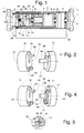
- Figure 1 is a schematic view in axial section a motorized winding tube according to a first mode of execution.
- Figure 2 is a perspective view of the two main components of the stop device automatic.
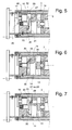
- Figure 3 shows detail of a second mode of execution, obtained by a modification of the first mode of execution.
- Figure 4 is a perspective view of the two main components of the second stop device mode of execution.
- Figures 5, 6 and 7 show three positions different from the device according to the second mode of execution.
- Figures 8, 9, 10 and 11 show, in section axial, a pneumatic embodiment of the device to retractable finger, in four successive positions.
- FIG. 12 is a partial view, in axial section, a third embodiment of the stop device.
- FIG. 13 is a partial view, in axial section, of a fourth embodiment.
- Figure 14 shows a detail of Figure 13.
- Figure 15 is an axial front view of a variant of the switch support.
- FIG. 16 represents a detail of FIG. 15.
- Figure 17 is a partial view of a fifth mode of execution.
- Figure 18 is a partial view of a sixth mode of execution.
- FIG. 1 shows a winding device roller shutter mounted in a window frame 1.
- this winding device includes a tubular motor housing 2 carried by a support 70 fixed to one side of the doorway and housed inside a supported winding tube 3, a side, by a ball bearing 4 carried by a plate 5 fixed on the other side of doorway 1, and on the other side, in rotation, by the motor housing 2.
- the tubular housing contains an electric motor 6 of which the rotor 7 has two outputs, one of which is connected to a reduction gear 8, including the output shaft 9, carried by a ball bearing 10, drives a disc 11 integral with the winding tube 3 and the other of which output, carried by a ball bearing 12, drives, by a friction coupling 13, a mounted disc 14 rotatably in the housing 2.
- the coupling to friction 13 therefore ensures a kinematic connection between motor 6 and disc 14.
- To the left of disc 14 is mounted a cylindrical support 15 fixed to the casing 2 and carrying a device 16 with retractable finger 30 comprising a rotary input mobile 49 integral a toothed wheel 17 engaged with a crown 18 to internal toothing integral with the winding tube 3.
- the disc 14 is integral with a penetrating shaft 19 freely in a blind bore 22 of the support 15 in which is housed a spring 20 pushing the shaft 19 and tending to maintain the coupling plates 13 One against the other.
- the disc 14 On its face, facing the support 15, the disc 14 has a radial rib 21.
- the cylindrical support 15 has, on its face in look of disc 14, two stops 23 and 24 between which is engaged the rib 21. These stops limit the rotation of the disc 14 and determine two stable positions on either side of its position median.
- the disc 14 has, on its opposite face of the support 15, two holes 27 and 28 arranged symmetrically relative to a plane containing the axis 31 of rotation of disc 14. Behind each of these holes 27 and 28, inside the disc 14, is arranged a switch 29.
- the retractable finger 30 of the finger device retractable 16 is oriented parallel to the axis 31 of the disc 14 and its axis is located in the plane of symmetry holes 27 and 28.
- the disc 14 tends to be driven by the coupling to friction 13 in a plane perpendicular to the finger actuation 30.
- the rotation of the winding tube 3, causes the device 30 to retract 16.
- the finger 30 then releases the disc 14 which can be driven in the other direction by a limited angle defined by the stop 24, so that the other hole 27 comes stand in front of finger 30.
- a engine restart can only be done in one direction reverse of the previous meaning. Therefore, when the user commands the shutter to stop intermediate position, for example downhill, must first order its ascent before be able to continue the descent, which can be considered a drawback. It may be even during commissioning.
- a lug 33 directed towards tree 19, slightly set back from the end of the finger 30.
- the disc 14 has a hole additional 34 located between holes 27 and 28, midway between these holes, and a flange 35 around of shaft 19, flange located in the path of lug 33, so that it is driven by the lug 33 during the retraction of the finger 30.
- FIGS 8 to 11 show an execution pneumatic retractable finger device 16.
- the device consists of a cylinder 40 divided into two chambers 41 and 42 by an intermediate wall 43 and containing two pistons 44 and 45.
- a spring 46 working in compression, is mounted between the wall intermediate 43 and the first piston 44.
- the first piston 44 has, on its face opposite to the spring 46, bell-shaped part 47 driven by a boss 48 formed, eccentrically, at the end of the input mobile 49 consisting of a shaft rotatably mounted in the cylinder 40 by means of a ball bearing 50.
- the piston 44 is also drilled in the center of a hole 51 closed, spring side, by a non-return valve 52.
- the second piston 45 provided with a seal 53, is provided, on one side, a tubular axis 54 passing through the wall intermediate 43 through a central hole and opening into the first chamber 41.
- the tightness of the passage is provided by a seal 55.
- the other face of the piston 45 is integral with an axis 56 crossing the bottom of the cylinder 40 by a sealed passage provided with a seal 57.
- the finger retractable 30 is formed in the extension of the axis 56.
- the inside of the axis tubular 54 communicates with an active chamber 58, located in front of the piston 45, through a passage 59 of which the access is, at rest, closed by a non-return valve ball 60.
- the active chamber 58 communicates with the exterior by a calibrated leak 61.
- a helical spring 62 working in compression, is mounted between the end of cylinder 40 and a flange 63 of the axis 56. This spring 62 therefore has tendency to pull the piston 45 towards the bottom of the cylinder 40, but the piston stroke is limited by a flange 64 formed at the end of the axis tubular 54 and which abuts against the wall 43.
- the input mobile 49 drives the piston 44 in a back and forth movement by its bell cam 47.
- the piston 44 with its non-return valve 52, works like a pump that drives the air out of room 41 in the active chamber 58 by the tubular axis 54 and the conduit 59.
- the compressed air accumulated in the chamber active 58 has the effect of pushing back the piston 45: the finger 30 begins to retract (Figure 9).
- the retractable finger device 16 can be produced mechanically. It can be made, for example, a centrifugal clutch with flyweights driven by the winding tube 3 via a speed multiplier, this centrifugal clutch driving a steep propeller screw on which is mounted a nut integral in translation with the finger 30 and pushed by a coil spring, so that the drive of the screw has the effect of rolling back the nut on the screw, the spring doing it again advance when the screw stops.
- the disc 14 could be driven by the winding tube.
- a example of execution is represented in figure 12. This execution can be considered as a modification of the execution shown in Figures 1 and 2 and so as to avoid unnecessary repetitions, the elements shown in Figure 1 have been designated by the same references, even if these have slight changes, such as removing the friction coupling between the rotor 7 and the disc 14.
- the axis 19 of the disc 14 here passes through the support 15 and its end carries one of the disks of a clutch to friction 71 of which the other disc is integral with a long pinion 72 rotatably mounted in support 70 at by means of a ball bearing 73.
- the long pinion 72 meshes with the toothed wheel 17.
- the discs of the clutch 71 are held against each other by a spring 74 bearing on the support 15. This device works in the same way as the device shown in Figures 1 and 2.
- the device shown in figure 12 can be modified so as to allow a restart in the same direction after a controlled stop.
- the coupling to friction 71 of figure 12 is replaced by a friction coupling 75 controlled electromagnetically simultaneously with the supply of the engine.
- the detail of this coupling is shown in figure 14. It includes a first part coupling 76 cylindrical cup-shaped mounted on one end 19a of the axis 19 with which it is integral in rotation, but mobile in translation, and a second part 77, also in bowl-shaped, integral with pinion 72.
- Parts 76 and 77 are surrounded by a coil 78 carried by a support 79 and powered by two wires 80.
- Parts 76 and 77 are entirely or partially made of material ferromagnetic, so that the excitation of the coil 78 has the effect of applying the parts 76 and 77 against each other and thus ensure a friction coupling.
- the coil 78 is excited, so that disc 14 is coupled in rotation at the winding tube 3.
- the finger 30 comes out of the central hole 34 and releases the disc 14, which the latter turns one way or the other, depending on the direction of rotation of the winding tube 3.
- the device then works like the device shown in Figures 3 and 4, except that the actuation of one of the switches by finger 30 has simultaneously for the purpose of cutting the supply of the coil 78 and thus uncoupling the disc 14 from the tube winding 3.
- the switch support constituted by the disc 14, having the function, by its displacement, of bringing one either of the switches opposite finger 30, this displacement does not have to be a movement of rotation but it could very well be a movement of translation, especially since this movement is of limited amplitude.
- An example of realization will be described in relation to Figure 15.
- the switch support shown in Figure 15 is a variant of the first mode of execution but it could very well be completed to constitute a variant of the second embodiment shown in Figures 3 and 4.
- the switch support 90 has, in this case, a rectangular parallelepiped shape and it's slidably mounted transversely to axis 31 of the assembly in a frame 91 of circular outline, fixed to motor casing 2. Sliding support 90 presents the holes 27 and 28 in each of which is mounted a switch 29, as in the first mode of execution.
- the support switch 90 In its underside, the support switch 90 has a central groove 92, trapezoidal shape and extending parallel to the axis 31. In this notch 92 is engaged the end 93, in the shape of a key bit, of a tree 94 connected to the friction coupling 13.
- the support 90 could, of course, be driven by the winding tube 3, as shown in the figure 12.
- the friction coupling could be made as shown in figure 15 and springs, arranged on each side of the support 90, would allow to obtain a middle position of the support 90, as in the case of FIGS. 13 and 14.
- the embodiment shown in Figure 17 is derived from the embodiment shown in Figure 12. In order to avoid repetition, the elements taken from figure 12 have been designated by the same reference numbers.
- the switch support 14 ' differs from the support 14 in that it is fixed to the casing 2 of the motor and in that it presents, on its face in look of the actuating finger 30, a pair of stops 95 determining the positions, facing towards the actuating finger 30 and switches.
- the support 15 ' is also pushed axially by a spring 97 in the direction of the friction coupling 71.
- support 15' is driven indirectly in rotation by the motor 6 via the tube winding 3, wheel 17, rotatably mounted and eccentrically on the support 15 ', and coupling 71. Positioning is ensured by the cleat 96 and the stops 95. With regard to the restart, this execution mode behaves like the first mode of execution.
- the friction coupling could be do by moving its elements in direction opposite.
- the friction coupling could be replaced by a hydraulic coupling.
- the embodiment according to Figures 1 and 2 could have only one switch, for example in front of the hole 28, ensuring the engine stops in a direction of rotation only.
Landscapes
- Engineering & Computer Science (AREA)
- Structural Engineering (AREA)
- Architecture (AREA)
- Civil Engineering (AREA)
- Operating, Guiding And Securing Of Roll- Type Closing Members (AREA)
- Motor And Converter Starters (AREA)
- Control Of Electric Motors In General (AREA)
- Control Of Direct Current Motors (AREA)
Applications Claiming Priority (2)
| Application Number | Priority Date | Filing Date | Title |
|---|---|---|---|
| FR9703766 | 1997-03-27 | ||
| FR9703766A FR2761547A1 (fr) | 1997-03-27 | 1997-03-27 | Dispositif d'arret automatique d'un moteur electrique entrainant un mobile en rotation |
Publications (1)
| Publication Number | Publication Date |
|---|---|
| EP0867594A1 true EP0867594A1 (de) | 1998-09-30 |
Family
ID=9505241
Family Applications (1)
| Application Number | Title | Priority Date | Filing Date |
|---|---|---|---|
| EP98810159A Withdrawn EP0867594A1 (de) | 1997-03-27 | 1998-02-27 | Automatische Bremsvorrichtung für einen Elektromotor, der ein drehendes Teil antreibt |
Country Status (3)
| Country | Link |
|---|---|
| EP (1) | EP0867594A1 (de) |
| ES (1) | ES2121727T1 (de) |
| FR (1) | FR2761547A1 (de) |
Cited By (3)
| Publication number | Priority date | Publication date | Assignee | Title |
|---|---|---|---|---|
| ITMI20081518A1 (it) * | 2008-08-13 | 2010-02-14 | Corrado Scata | Dispositivo di supporto di motori elettrici per tapparelle |
| WO2011112105A1 (en) * | 2010-03-07 | 2011-09-15 | Franc Gardiner Sp. Z.O.O. | Mechanism controlling the rotation of roller blinds winding roller with a spring drive |
| CN106193980A (zh) * | 2016-08-31 | 2016-12-07 | 肖爱平 | 一种遇阻保护器及卷闸门 |
Citations (5)
| Publication number | Priority date | Publication date | Assignee | Title |
|---|---|---|---|---|
| FR2052208A5 (de) * | 1969-07-29 | 1971-04-09 | Henri Peignen Ets | |
| WO1981003715A1 (fr) * | 1980-06-11 | 1981-12-24 | Faiveley Sa | Dispositif pour couper automatiquement l'alimentation electrique d'un moteur et son utilisation |
| EP0497711A1 (de) * | 1991-01-14 | 1992-08-05 | Simu | Sicherungseinrichtung für elektrische Betätigungseinrichtung für Rolläden |
| DE4440449A1 (de) | 1994-11-14 | 1995-06-29 | Elero Antrieb Sonnenschutz | Verfahren und Vorrichtung zur Stillstandssteuerung von elektromotorisch betriebenen Rolläden oder dergleichen |
| EP0703344A1 (de) | 1994-09-22 | 1996-03-27 | Gottlieb Klenk | Vorrichtung zur selbsttätigen Endabschaltung eines Rollvorhangs, insbesondere eines Rollandenpanzers |
-
1997
- 1997-03-27 FR FR9703766A patent/FR2761547A1/fr active Pending
-
1998
- 1998-02-27 ES ES98810159T patent/ES2121727T1/es active Pending
- 1998-02-27 EP EP98810159A patent/EP0867594A1/de not_active Withdrawn
Patent Citations (5)
| Publication number | Priority date | Publication date | Assignee | Title |
|---|---|---|---|---|
| FR2052208A5 (de) * | 1969-07-29 | 1971-04-09 | Henri Peignen Ets | |
| WO1981003715A1 (fr) * | 1980-06-11 | 1981-12-24 | Faiveley Sa | Dispositif pour couper automatiquement l'alimentation electrique d'un moteur et son utilisation |
| EP0497711A1 (de) * | 1991-01-14 | 1992-08-05 | Simu | Sicherungseinrichtung für elektrische Betätigungseinrichtung für Rolläden |
| EP0703344A1 (de) | 1994-09-22 | 1996-03-27 | Gottlieb Klenk | Vorrichtung zur selbsttätigen Endabschaltung eines Rollvorhangs, insbesondere eines Rollandenpanzers |
| DE4440449A1 (de) | 1994-11-14 | 1995-06-29 | Elero Antrieb Sonnenschutz | Verfahren und Vorrichtung zur Stillstandssteuerung von elektromotorisch betriebenen Rolläden oder dergleichen |
Cited By (4)
| Publication number | Priority date | Publication date | Assignee | Title |
|---|---|---|---|---|
| ITMI20081518A1 (it) * | 2008-08-13 | 2010-02-14 | Corrado Scata | Dispositivo di supporto di motori elettrici per tapparelle |
| WO2011112105A1 (en) * | 2010-03-07 | 2011-09-15 | Franc Gardiner Sp. Z.O.O. | Mechanism controlling the rotation of roller blinds winding roller with a spring drive |
| AU2010347808B2 (en) * | 2010-03-07 | 2016-11-10 | Franc Gardiner Sp. Z.O.O. | Mechanism controlling the rotation of roller blinds winding roller with a spring drive |
| CN106193980A (zh) * | 2016-08-31 | 2016-12-07 | 肖爱平 | 一种遇阻保护器及卷闸门 |
Also Published As
| Publication number | Publication date |
|---|---|
| FR2761547A1 (fr) | 1998-10-02 |
| ES2121727T1 (es) | 1998-12-16 |
Similar Documents
| Publication | Publication Date | Title |
|---|---|---|
| EP3581742B1 (de) | Flächenbündiger türgriff und verfahren zum betrieb davon | |
| FR2490279A1 (fr) | Dispositif de demarrage de moteur comportant un accouplement unidirectionnel | |
| EP0881652B1 (de) | Federkraftantrieb für ein Schaltgerät, insbesondere für einen Lastschalter | |
| EP1259696B1 (de) | Motorisierter rolladen mit automatischen blockiervorrichtungen | |
| EP0936342B1 (de) | Steuerungsvorrichtung eines Elektomotors, der ein Teil antreibt | |
| EP1324466B1 (de) | Drehmomentübertragungs- und Scheibenbremsenvorrichtung | |
| EP0844362B1 (de) | Vorrichtung zum automatischen Abschalten eines Motorantriebes einer Rolladenwickelwelle | |
| EP0867594A1 (de) | Automatische Bremsvorrichtung für einen Elektromotor, der ein drehendes Teil antreibt | |
| EP0497711B1 (de) | Sicherungseinrichtung für elektrische Betätigungseinrichtung für Rolläden | |
| FR2611549A3 (fr) | Cisaille motorisee auto-alimentee | |
| EP0193466B1 (de) | Elektrische Vorrichtung zum Betätigen der Drosselklappe in einem Innenverbrennungsmotor | |
| EP0803611A1 (de) | Verfahren zum Betrieb eines Speiseweges für Anlage zum Markieren von Strassendecken | |
| EP1676013B1 (de) | Vorrichtung zur steuerung des öffnens eines beweglichen elements, wie zum beispiel einer rauchabzugsklappe | |
| EP0604330B1 (de) | Modularer Schutzschalter in Verbindung mit einer Fernbedienungseinheit | |
| EP1427908B1 (de) | Elastische kupplung zur ausrichtung der drehwinkelstellung zweier teile | |
| FR2885158A1 (fr) | Vehicule avec un hayon | |
| FR2705271A1 (fr) | Dispositif de protection de chaîne de tronçonneuse à bois du type portatif. | |
| FR2740824A1 (fr) | Installation de fermeture ou de protection solaire motorisee | |
| FR3081183A1 (fr) | Systeme d'actionnement d'un volet roulant et d'une toile | |
| EP0844363B1 (de) | Antriebsvorrichtung für Rolladen oder dergleichen | |
| EP1500778B1 (de) | Verschluss- oder Sonnenschutzeinrichtung mit einer Sicherheitsvorrichtung | |
| EP1649478A1 (de) | Dreheingriffs-verriegelungsmechanismus für automatische sicherheitsabtrennung | |
| FR2962385A1 (fr) | Mecanisme d'articulation et siege de vehicule comportant un tel mecanisme. | |
| FR2695971A1 (fr) | Groupe de freinage avec déblocage de secours pour moteurs électriques. | |
| BE875496R (fr) | Dispositif anti-chute automatique pour installation de levage motorisee |
Legal Events
| Date | Code | Title | Description |
|---|---|---|---|
| PUAI | Public reference made under article 153(3) epc to a published international application that has entered the european phase |
Free format text: ORIGINAL CODE: 0009012 |
|
| AK | Designated contracting states |
Kind code of ref document: A1 Designated state(s): AT BE CH DE DK ES FI FR GB GR IE IT LI LU MC NL PT SE |
|
| AX | Request for extension of the european patent |
Free format text: AL;LT;LV;MK;RO;SI |
|
| REG | Reference to a national code |
Ref country code: ES Ref legal event code: BA2A Ref document number: 2121727 Country of ref document: ES Kind code of ref document: T1 |
|
| AKX | Designation fees paid | ||
| STAA | Information on the status of an ep patent application or granted ep patent |
Free format text: STATUS: THE APPLICATION IS DEEMED TO BE WITHDRAWN |
|
| 18D | Application deemed to be withdrawn |
Effective date: 19990331 |