EP0867643A2 - Halbautomatische Schaltdurchführung eines Splitterverbundgetriebes - Google Patents
Halbautomatische Schaltdurchführung eines Splitterverbundgetriebes Download PDFInfo
- Publication number
- EP0867643A2 EP0867643A2 EP98301873A EP98301873A EP0867643A2 EP 0867643 A2 EP0867643 A2 EP 0867643A2 EP 98301873 A EP98301873 A EP 98301873A EP 98301873 A EP98301873 A EP 98301873A EP 0867643 A2 EP0867643 A2 EP 0867643A2
- Authority
- EP
- European Patent Office
- Prior art keywords
- splitter
- gear ratio
- engine
- target gear
- clutch
- Prior art date
- Legal status (The legal status is an assumption and is not a legal conclusion. Google has not performed a legal analysis and makes no representation as to the accuracy of the status listed.)
- Granted
Links
- 230000005540 biological transmission Effects 0.000 title claims abstract description 94
- 150000001875 compounds Chemical class 0.000 title claims abstract description 15
- 230000001360 synchronised effect Effects 0.000 claims abstract description 35
- 230000007935 neutral effect Effects 0.000 claims abstract description 32
- 230000006870 function Effects 0.000 claims description 6
- 239000000446 fuel Substances 0.000 claims description 3
- 230000000979 retarding effect Effects 0.000 claims 2
- 238000000034 method Methods 0.000 description 10
- 230000009347 mechanical transmission Effects 0.000 description 9
- 230000009471 action Effects 0.000 description 3
- 230000000712 assembly Effects 0.000 description 3
- 238000000429 assembly Methods 0.000 description 3
- 230000008859 change Effects 0.000 description 3
- 230000002441 reversible effect Effects 0.000 description 3
- 238000012790 confirmation Methods 0.000 description 2
- 230000009467 reduction Effects 0.000 description 2
- 230000004044 response Effects 0.000 description 2
- 230000001133 acceleration Effects 0.000 description 1
- 230000003213 activating effect Effects 0.000 description 1
- 238000010586 diagram Methods 0.000 description 1
- 230000008676 import Effects 0.000 description 1
- 230000002401 inhibitory effect Effects 0.000 description 1
- 230000000977 initiatory effect Effects 0.000 description 1
- 230000000670 limiting effect Effects 0.000 description 1
- 230000036961 partial effect Effects 0.000 description 1
- 230000035484 reaction time Effects 0.000 description 1
- 230000033764 rhythmic process Effects 0.000 description 1
Images


Classifications
-
- B—PERFORMING OPERATIONS; TRANSPORTING
- B60—VEHICLES IN GENERAL
- B60W—CONJOINT CONTROL OF VEHICLE SUB-UNITS OF DIFFERENT TYPE OR DIFFERENT FUNCTION; CONTROL SYSTEMS SPECIALLY ADAPTED FOR HYBRID VEHICLES; ROAD VEHICLE DRIVE CONTROL SYSTEMS FOR PURPOSES NOT RELATED TO THE CONTROL OF A PARTICULAR SUB-UNIT
- B60W10/00—Conjoint control of vehicle sub-units of different type or different function
- B60W10/04—Conjoint control of vehicle sub-units of different type or different function including control of propulsion units
- B60W10/06—Conjoint control of vehicle sub-units of different type or different function including control of propulsion units including control of combustion engines
-
- B—PERFORMING OPERATIONS; TRANSPORTING
- B60—VEHICLES IN GENERAL
- B60W—CONJOINT CONTROL OF VEHICLE SUB-UNITS OF DIFFERENT TYPE OR DIFFERENT FUNCTION; CONTROL SYSTEMS SPECIALLY ADAPTED FOR HYBRID VEHICLES; ROAD VEHICLE DRIVE CONTROL SYSTEMS FOR PURPOSES NOT RELATED TO THE CONTROL OF A PARTICULAR SUB-UNIT
- B60W10/00—Conjoint control of vehicle sub-units of different type or different function
- B60W10/10—Conjoint control of vehicle sub-units of different type or different function including control of change-speed gearings
- B60W10/11—Stepped gearings
- B60W10/111—Stepped gearings with separate change-speed gear trains arranged in series
-
- B—PERFORMING OPERATIONS; TRANSPORTING
- B60—VEHICLES IN GENERAL
- B60W—CONJOINT CONTROL OF VEHICLE SUB-UNITS OF DIFFERENT TYPE OR DIFFERENT FUNCTION; CONTROL SYSTEMS SPECIALLY ADAPTED FOR HYBRID VEHICLES; ROAD VEHICLE DRIVE CONTROL SYSTEMS FOR PURPOSES NOT RELATED TO THE CONTROL OF A PARTICULAR SUB-UNIT
- B60W30/00—Purposes of road vehicle drive control systems not related to the control of a particular sub-unit, e.g. of systems using conjoint control of vehicle sub-units
- B60W30/18—Propelling the vehicle
- B60W30/19—Improvement of gear change, e.g. by synchronisation or smoothing gear shift
-
- F—MECHANICAL ENGINEERING; LIGHTING; HEATING; WEAPONS; BLASTING
- F16—ENGINEERING ELEMENTS AND UNITS; GENERAL MEASURES FOR PRODUCING AND MAINTAINING EFFECTIVE FUNCTIONING OF MACHINES OR INSTALLATIONS; THERMAL INSULATION IN GENERAL
- F16H—GEARING
- F16H61/00—Control functions within control units of change-speed- or reversing-gearings for conveying rotary motion ; Control of exclusively fluid gearing, friction gearing, gearings with endless flexible members or other particular types of gearing
- F16H61/70—Control functions within control units of change-speed- or reversing-gearings for conveying rotary motion ; Control of exclusively fluid gearing, friction gearing, gearings with endless flexible members or other particular types of gearing specially adapted for change-speed gearing in group arrangement, i.e. with separate change-speed gear trains arranged in series, e.g. range or overdrive-type gearing arrangements
- F16H61/702—Control functions within control units of change-speed- or reversing-gearings for conveying rotary motion ; Control of exclusively fluid gearing, friction gearing, gearings with endless flexible members or other particular types of gearing specially adapted for change-speed gearing in group arrangement, i.e. with separate change-speed gear trains arranged in series, e.g. range or overdrive-type gearing arrangements using electric or electrohydraulic control means
-
- F—MECHANICAL ENGINEERING; LIGHTING; HEATING; WEAPONS; BLASTING
- F16—ENGINEERING ELEMENTS AND UNITS; GENERAL MEASURES FOR PRODUCING AND MAINTAINING EFFECTIVE FUNCTIONING OF MACHINES OR INSTALLATIONS; THERMAL INSULATION IN GENERAL
- F16H—GEARING
- F16H63/00—Control outputs from the control unit to change-speed- or reversing-gearings for conveying rotary motion or to other devices than the final output mechanism
- F16H63/40—Control outputs from the control unit to change-speed- or reversing-gearings for conveying rotary motion or to other devices than the final output mechanism comprising signals other than signals for actuating the final output mechanisms
- F16H63/44—Signals to the control unit of auxiliary gearing
-
- B—PERFORMING OPERATIONS; TRANSPORTING
- B60—VEHICLES IN GENERAL
- B60W—CONJOINT CONTROL OF VEHICLE SUB-UNITS OF DIFFERENT TYPE OR DIFFERENT FUNCTION; CONTROL SYSTEMS SPECIALLY ADAPTED FOR HYBRID VEHICLES; ROAD VEHICLE DRIVE CONTROL SYSTEMS FOR PURPOSES NOT RELATED TO THE CONTROL OF A PARTICULAR SUB-UNIT
- B60W50/00—Details of control systems for road vehicle drive control not related to the control of a particular sub-unit, e.g. process diagnostic or vehicle driver interfaces
- B60W2050/0001—Details of the control system
- B60W2050/0043—Signal treatments, identification of variables or parameters, parameter estimation or state estimation
- B60W2050/0044—In digital systems
- B60W2050/0045—In digital systems using databus protocols
-
- B—PERFORMING OPERATIONS; TRANSPORTING
- B60—VEHICLES IN GENERAL
- B60W—CONJOINT CONTROL OF VEHICLE SUB-UNITS OF DIFFERENT TYPE OR DIFFERENT FUNCTION; CONTROL SYSTEMS SPECIALLY ADAPTED FOR HYBRID VEHICLES; ROAD VEHICLE DRIVE CONTROL SYSTEMS FOR PURPOSES NOT RELATED TO THE CONTROL OF A PARTICULAR SUB-UNIT
- B60W2510/00—Input parameters relating to a particular sub-units
- B60W2510/02—Clutches
- B60W2510/0208—Clutch engagement state, e.g. engaged or disengaged
- B60W2510/0225—Clutch actuator position
-
- B—PERFORMING OPERATIONS; TRANSPORTING
- B60—VEHICLES IN GENERAL
- B60W—CONJOINT CONTROL OF VEHICLE SUB-UNITS OF DIFFERENT TYPE OR DIFFERENT FUNCTION; CONTROL SYSTEMS SPECIALLY ADAPTED FOR HYBRID VEHICLES; ROAD VEHICLE DRIVE CONTROL SYSTEMS FOR PURPOSES NOT RELATED TO THE CONTROL OF A PARTICULAR SUB-UNIT
- B60W2510/00—Input parameters relating to a particular sub-units
- B60W2510/10—Change speed gearings
- B60W2510/1015—Input shaft speed, e.g. turbine speed
-
- B—PERFORMING OPERATIONS; TRANSPORTING
- B60—VEHICLES IN GENERAL
- B60W—CONJOINT CONTROL OF VEHICLE SUB-UNITS OF DIFFERENT TYPE OR DIFFERENT FUNCTION; CONTROL SYSTEMS SPECIALLY ADAPTED FOR HYBRID VEHICLES; ROAD VEHICLE DRIVE CONTROL SYSTEMS FOR PURPOSES NOT RELATED TO THE CONTROL OF A PARTICULAR SUB-UNIT
- B60W2510/00—Input parameters relating to a particular sub-units
- B60W2510/10—Change speed gearings
- B60W2510/104—Output speed
-
- B—PERFORMING OPERATIONS; TRANSPORTING
- B60—VEHICLES IN GENERAL
- B60W—CONJOINT CONTROL OF VEHICLE SUB-UNITS OF DIFFERENT TYPE OR DIFFERENT FUNCTION; CONTROL SYSTEMS SPECIALLY ADAPTED FOR HYBRID VEHICLES; ROAD VEHICLE DRIVE CONTROL SYSTEMS FOR PURPOSES NOT RELATED TO THE CONTROL OF A PARTICULAR SUB-UNIT
- B60W2710/00—Output or target parameters relating to a particular sub-units
- B60W2710/06—Combustion engines, Gas turbines
- B60W2710/0644—Engine speed
-
- F—MECHANICAL ENGINEERING; LIGHTING; HEATING; WEAPONS; BLASTING
- F16—ENGINEERING ELEMENTS AND UNITS; GENERAL MEASURES FOR PRODUCING AND MAINTAINING EFFECTIVE FUNCTIONING OF MACHINES OR INSTALLATIONS; THERMAL INSULATION IN GENERAL
- F16H—GEARING
- F16H59/00—Control inputs to control units of change-speed- or reversing-gearings for conveying rotary motion
- F16H59/68—Inputs being a function of gearing status
- F16H2059/6823—Sensing neutral state of the transmission
-
- F—MECHANICAL ENGINEERING; LIGHTING; HEATING; WEAPONS; BLASTING
- F16—ENGINEERING ELEMENTS AND UNITS; GENERAL MEASURES FOR PRODUCING AND MAINTAINING EFFECTIVE FUNCTIONING OF MACHINES OR INSTALLATIONS; THERMAL INSULATION IN GENERAL
- F16H—GEARING
- F16H61/00—Control functions within control units of change-speed- or reversing-gearings for conveying rotary motion ; Control of exclusively fluid gearing, friction gearing, gearings with endless flexible members or other particular types of gearing
- F16H61/04—Smoothing ratio shift
- F16H61/0403—Synchronisation before shifting
- F16H2061/0411—Synchronisation before shifting by control of shaft brakes
-
- F—MECHANICAL ENGINEERING; LIGHTING; HEATING; WEAPONS; BLASTING
- F16—ENGINEERING ELEMENTS AND UNITS; GENERAL MEASURES FOR PRODUCING AND MAINTAINING EFFECTIVE FUNCTIONING OF MACHINES OR INSTALLATIONS; THERMAL INSULATION IN GENERAL
- F16H—GEARING
- F16H61/00—Control functions within control units of change-speed- or reversing-gearings for conveying rotary motion ; Control of exclusively fluid gearing, friction gearing, gearings with endless flexible members or other particular types of gearing
- F16H61/04—Smoothing ratio shift
- F16H2061/047—Smoothing ratio shift by preventing or solving a tooth butt situation upon engagement failure due to misalignment of teeth
-
- F—MECHANICAL ENGINEERING; LIGHTING; HEATING; WEAPONS; BLASTING
- F16—ENGINEERING ELEMENTS AND UNITS; GENERAL MEASURES FOR PRODUCING AND MAINTAINING EFFECTIVE FUNCTIONING OF MACHINES OR INSTALLATIONS; THERMAL INSULATION IN GENERAL
- F16H—GEARING
- F16H2306/00—Shifting
- F16H2306/40—Shifting activities
- F16H2306/44—Removing torque from current gears
-
- F—MECHANICAL ENGINEERING; LIGHTING; HEATING; WEAPONS; BLASTING
- F16—ENGINEERING ELEMENTS AND UNITS; GENERAL MEASURES FOR PRODUCING AND MAINTAINING EFFECTIVE FUNCTIONING OF MACHINES OR INSTALLATIONS; THERMAL INSULATION IN GENERAL
- F16H—GEARING
- F16H2306/00—Shifting
- F16H2306/40—Shifting activities
- F16H2306/46—Uncoupling of current gear
-
- F—MECHANICAL ENGINEERING; LIGHTING; HEATING; WEAPONS; BLASTING
- F16—ENGINEERING ELEMENTS AND UNITS; GENERAL MEASURES FOR PRODUCING AND MAINTAINING EFFECTIVE FUNCTIONING OF MACHINES OR INSTALLATIONS; THERMAL INSULATION IN GENERAL
- F16H—GEARING
- F16H2306/00—Shifting
- F16H2306/40—Shifting activities
- F16H2306/48—Synchronising of new gear
-
- F—MECHANICAL ENGINEERING; LIGHTING; HEATING; WEAPONS; BLASTING
- F16—ENGINEERING ELEMENTS AND UNITS; GENERAL MEASURES FOR PRODUCING AND MAINTAINING EFFECTIVE FUNCTIONING OF MACHINES OR INSTALLATIONS; THERMAL INSULATION IN GENERAL
- F16H—GEARING
- F16H2306/00—Shifting
- F16H2306/40—Shifting activities
- F16H2306/54—Synchronising engine speed to transmission input speed
-
- F—MECHANICAL ENGINEERING; LIGHTING; HEATING; WEAPONS; BLASTING
- F16—ENGINEERING ELEMENTS AND UNITS; GENERAL MEASURES FOR PRODUCING AND MAINTAINING EFFECTIVE FUNCTIONING OF MACHINES OR INSTALLATIONS; THERMAL INSULATION IN GENERAL
- F16H—GEARING
- F16H59/00—Control inputs to control units of change-speed- or reversing-gearings for conveying rotary motion
- F16H59/02—Selector apparatus
- F16H59/0217—Selector apparatus with electric switches or sensors not for gear or range selection, e.g. for controlling auxiliary devices
-
- F—MECHANICAL ENGINEERING; LIGHTING; HEATING; WEAPONS; BLASTING
- F16—ENGINEERING ELEMENTS AND UNITS; GENERAL MEASURES FOR PRODUCING AND MAINTAINING EFFECTIVE FUNCTIONING OF MACHINES OR INSTALLATIONS; THERMAL INSULATION IN GENERAL
- F16H—GEARING
- F16H59/00—Control inputs to control units of change-speed- or reversing-gearings for conveying rotary motion
- F16H59/02—Selector apparatus
- F16H59/08—Range selector apparatus
-
- F—MECHANICAL ENGINEERING; LIGHTING; HEATING; WEAPONS; BLASTING
- F16—ENGINEERING ELEMENTS AND UNITS; GENERAL MEASURES FOR PRODUCING AND MAINTAINING EFFECTIVE FUNCTIONING OF MACHINES OR INSTALLATIONS; THERMAL INSULATION IN GENERAL
- F16H—GEARING
- F16H59/00—Control inputs to control units of change-speed- or reversing-gearings for conveying rotary motion
- F16H59/36—Inputs being a function of speed
- F16H59/38—Inputs being a function of speed of gearing elements
- F16H59/40—Output shaft speed
-
- F—MECHANICAL ENGINEERING; LIGHTING; HEATING; WEAPONS; BLASTING
- F16—ENGINEERING ELEMENTS AND UNITS; GENERAL MEASURES FOR PRODUCING AND MAINTAINING EFFECTIVE FUNCTIONING OF MACHINES OR INSTALLATIONS; THERMAL INSULATION IN GENERAL
- F16H—GEARING
- F16H59/00—Control inputs to control units of change-speed- or reversing-gearings for conveying rotary motion
- F16H59/36—Inputs being a function of speed
- F16H59/38—Inputs being a function of speed of gearing elements
- F16H59/42—Input shaft speed
-
- F—MECHANICAL ENGINEERING; LIGHTING; HEATING; WEAPONS; BLASTING
- F16—ENGINEERING ELEMENTS AND UNITS; GENERAL MEASURES FOR PRODUCING AND MAINTAINING EFFECTIVE FUNCTIONING OF MACHINES OR INSTALLATIONS; THERMAL INSULATION IN GENERAL
- F16H—GEARING
- F16H59/00—Control inputs to control units of change-speed- or reversing-gearings for conveying rotary motion
- F16H59/36—Inputs being a function of speed
- F16H59/46—Inputs being a function of speed dependent on a comparison between speeds
-
- F—MECHANICAL ENGINEERING; LIGHTING; HEATING; WEAPONS; BLASTING
- F16—ENGINEERING ELEMENTS AND UNITS; GENERAL MEASURES FOR PRODUCING AND MAINTAINING EFFECTIVE FUNCTIONING OF MACHINES OR INSTALLATIONS; THERMAL INSULATION IN GENERAL
- F16H—GEARING
- F16H59/00—Control inputs to control units of change-speed- or reversing-gearings for conveying rotary motion
- F16H59/68—Inputs being a function of gearing status
- F16H59/70—Inputs being a function of gearing status dependent on the ratio established
-
- F—MECHANICAL ENGINEERING; LIGHTING; HEATING; WEAPONS; BLASTING
- F16—ENGINEERING ELEMENTS AND UNITS; GENERAL MEASURES FOR PRODUCING AND MAINTAINING EFFECTIVE FUNCTIONING OF MACHINES OR INSTALLATIONS; THERMAL INSULATION IN GENERAL
- F16H—GEARING
- F16H61/00—Control functions within control units of change-speed- or reversing-gearings for conveying rotary motion ; Control of exclusively fluid gearing, friction gearing, gearings with endless flexible members or other particular types of gearing
- F16H61/02—Control functions within control units of change-speed- or reversing-gearings for conveying rotary motion ; Control of exclusively fluid gearing, friction gearing, gearings with endless flexible members or other particular types of gearing characterised by the signals used
- F16H61/0202—Control functions within control units of change-speed- or reversing-gearings for conveying rotary motion ; Control of exclusively fluid gearing, friction gearing, gearings with endless flexible members or other particular types of gearing characterised by the signals used the signals being electric
- F16H61/0248—Control units where shifting is directly initiated by the driver, e.g. semi-automatic transmissions
-
- F—MECHANICAL ENGINEERING; LIGHTING; HEATING; WEAPONS; BLASTING
- F16—ENGINEERING ELEMENTS AND UNITS; GENERAL MEASURES FOR PRODUCING AND MAINTAINING EFFECTIVE FUNCTIONING OF MACHINES OR INSTALLATIONS; THERMAL INSULATION IN GENERAL
- F16H—GEARING
- F16H61/00—Control functions within control units of change-speed- or reversing-gearings for conveying rotary motion ; Control of exclusively fluid gearing, friction gearing, gearings with endless flexible members or other particular types of gearing
- F16H61/04—Smoothing ratio shift
- F16H61/0403—Synchronisation before shifting
-
- F—MECHANICAL ENGINEERING; LIGHTING; HEATING; WEAPONS; BLASTING
- F16—ENGINEERING ELEMENTS AND UNITS; GENERAL MEASURES FOR PRODUCING AND MAINTAINING EFFECTIVE FUNCTIONING OF MACHINES OR INSTALLATIONS; THERMAL INSULATION IN GENERAL
- F16H—GEARING
- F16H61/00—Control functions within control units of change-speed- or reversing-gearings for conveying rotary motion ; Control of exclusively fluid gearing, friction gearing, gearings with endless flexible members or other particular types of gearing
- F16H61/04—Smoothing ratio shift
- F16H61/0437—Smoothing ratio shift by using electrical signals
-
- F—MECHANICAL ENGINEERING; LIGHTING; HEATING; WEAPONS; BLASTING
- F16—ENGINEERING ELEMENTS AND UNITS; GENERAL MEASURES FOR PRODUCING AND MAINTAINING EFFECTIVE FUNCTIONING OF MACHINES OR INSTALLATIONS; THERMAL INSULATION IN GENERAL
- F16H—GEARING
- F16H61/00—Control functions within control units of change-speed- or reversing-gearings for conveying rotary motion ; Control of exclusively fluid gearing, friction gearing, gearings with endless flexible members or other particular types of gearing
- F16H61/04—Smoothing ratio shift
- F16H61/08—Timing control
-
- F—MECHANICAL ENGINEERING; LIGHTING; HEATING; WEAPONS; BLASTING
- F16—ENGINEERING ELEMENTS AND UNITS; GENERAL MEASURES FOR PRODUCING AND MAINTAINING EFFECTIVE FUNCTIONING OF MACHINES OR INSTALLATIONS; THERMAL INSULATION IN GENERAL
- F16H—GEARING
- F16H61/00—Control functions within control units of change-speed- or reversing-gearings for conveying rotary motion ; Control of exclusively fluid gearing, friction gearing, gearings with endless flexible members or other particular types of gearing
- F16H61/68—Control functions within control units of change-speed- or reversing-gearings for conveying rotary motion ; Control of exclusively fluid gearing, friction gearing, gearings with endless flexible members or other particular types of gearing specially adapted for stepped gearings
- F16H61/682—Control functions within control units of change-speed- or reversing-gearings for conveying rotary motion ; Control of exclusively fluid gearing, friction gearing, gearings with endless flexible members or other particular types of gearing specially adapted for stepped gearings with interruption of drive
-
- F—MECHANICAL ENGINEERING; LIGHTING; HEATING; WEAPONS; BLASTING
- F16—ENGINEERING ELEMENTS AND UNITS; GENERAL MEASURES FOR PRODUCING AND MAINTAINING EFFECTIVE FUNCTIONING OF MACHINES OR INSTALLATIONS; THERMAL INSULATION IN GENERAL
- F16H—GEARING
- F16H61/00—Control functions within control units of change-speed- or reversing-gearings for conveying rotary motion ; Control of exclusively fluid gearing, friction gearing, gearings with endless flexible members or other particular types of gearing
- F16H61/70—Control functions within control units of change-speed- or reversing-gearings for conveying rotary motion ; Control of exclusively fluid gearing, friction gearing, gearings with endless flexible members or other particular types of gearing specially adapted for change-speed gearing in group arrangement, i.e. with separate change-speed gear trains arranged in series, e.g. range or overdrive-type gearing arrangements
-
- F—MECHANICAL ENGINEERING; LIGHTING; HEATING; WEAPONS; BLASTING
- F16—ENGINEERING ELEMENTS AND UNITS; GENERAL MEASURES FOR PRODUCING AND MAINTAINING EFFECTIVE FUNCTIONING OF MACHINES OR INSTALLATIONS; THERMAL INSULATION IN GENERAL
- F16H—GEARING
- F16H63/00—Control outputs from the control unit to change-speed- or reversing-gearings for conveying rotary motion or to other devices than the final output mechanism
- F16H63/40—Control outputs from the control unit to change-speed- or reversing-gearings for conveying rotary motion or to other devices than the final output mechanism comprising signals other than signals for actuating the final output mechanisms
- F16H63/42—Ratio indicator devices
-
- F—MECHANICAL ENGINEERING; LIGHTING; HEATING; WEAPONS; BLASTING
- F16—ENGINEERING ELEMENTS AND UNITS; GENERAL MEASURES FOR PRODUCING AND MAINTAINING EFFECTIVE FUNCTIONING OF MACHINES OR INSTALLATIONS; THERMAL INSULATION IN GENERAL
- F16H—GEARING
- F16H63/00—Control outputs from the control unit to change-speed- or reversing-gearings for conveying rotary motion or to other devices than the final output mechanism
- F16H63/40—Control outputs from the control unit to change-speed- or reversing-gearings for conveying rotary motion or to other devices than the final output mechanism comprising signals other than signals for actuating the final output mechanisms
- F16H63/50—Signals to an engine or motor
- F16H63/502—Signals to an engine or motor for smoothing gear shifts
-
- Y—GENERAL TAGGING OF NEW TECHNOLOGICAL DEVELOPMENTS; GENERAL TAGGING OF CROSS-SECTIONAL TECHNOLOGIES SPANNING OVER SEVERAL SECTIONS OF THE IPC; TECHNICAL SUBJECTS COVERED BY FORMER USPC CROSS-REFERENCE ART COLLECTIONS [XRACs] AND DIGESTS
- Y10—TECHNICAL SUBJECTS COVERED BY FORMER USPC
- Y10T—TECHNICAL SUBJECTS COVERED BY FORMER US CLASSIFICATION
- Y10T74/00—Machine element or mechanism
- Y10T74/19—Gearing
- Y10T74/19219—Interchangeably locked
- Y10T74/19251—Control mechanism
Definitions
- the present invention relates to a semi-automatic shift implementation control system/method for semi-automatic shifting of a lever-shifted, splitter-type mechanical transmission. More particularly, in a preferred embodiment of the present invention, a splitter or combined splitter-and-range-type compound transmission is provided with a splitter clutch at the output end of the transmission and with controls and actuators for manually performed dynamic forward main section shifting, by lever shifting, without requiring manual throttle manipulation to synchronize for engaging the target gear ratio, as is done for shifting a manual synchronized transmission. In a preferred embodiment, an intent-to-shift sensor is provided, allowing the transmission to be manually shifted without master clutch manipulation, if desired.
- Semi-automatic shift implementation systems for compound mechanical transmissions wherein, upon manual shifting into a highest grouping of gear ratios, automatic shifting within only that highest grouping is provided, are known in the prior art and are disclosed in U.S. Pats. No. 4,722,248 and 5,038,627.
- Semi-automatic shift implementation systems for mechanical transmissions wherein the vehicle operator is required to manually cause a torque interruption and/or achieve synchronous conditions are known in the prior art and are disclosed in U.S. Pat. No. 5,053,961.
- At least partially automated systems wherein engine fuel control, such as engine dither, is utilized to cause non-torque-lock conditions for shifting into neutral without requiring master clutch manipulation and/or to synchronize for the target gear ratio are known in the prior art and are disclosed in U.S. Pats. No. 4,850,236; 5,105,357; 5,569,115; 5,523,477; 5,582,558 and allowed copending application 08/649,833.
- U.S. Pat. No. 5,435,212 discloses a semi-automatic shift implementation system which, for each lever position, has automatic splitter shifting, which allows a "(2+1)x(2)x(2)" type compound 10-speed transmission to be driven with the ease of a 5-speed manual transmission.
- a control system/method for a transmission, a splitter-type compound mechanical transmission with the splitter or the combined splitter-range auxiliary section at the output end of the transmission having relatively simple and inexpensive controls, sensors and actuators wherein forward main section ratio shifts (i.e. , lever shifts) are manually implemented in the same manner as shifting a synchronized automotive transmission, without the requirement of manual splitter shift selection and with automatic engine controls to synchronize the engine for the target gear ratio, and dynamic forward splitter-only shifts for each forward main section ratio are automatically implemented or, preferably, fully automatic.
- range shifting will be automatically selected by shift lever movement, as is known in commercially available "double-H" type controls.
- a display will be utilized to inform the driver of the suggested target ratio and/or of the ratio automatically synchronized for and/or to inform the operator that sufficiently synchronous conditions exist for completion of a shift and/or an intent-to-shift sensor will be utilized to sense when an operator intends to shift from a currently engaged ratio into neutral and then into the target ratio for causing preselection of the required splitter shift and causing the engine to be fueled to relieve or minimize torque-lock conditions, allowing the driver the option to shift without master clutch manipulation.
- a transmission input shaft or inertia brake operated by the system controller, is provided for increasing the rapidity of upshifts.
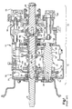
- Figs. 1 and 1A are a plan view of a combined range-and-splitter-type compound transmission.
- Fig. 2 illustrates a prior art shift pattern for the transmission of Fig. 1.
- Fig. 3 is a schematic illustration, in block diagram format, of a preferred embodiment of the semi-automated shift implementation transmission system of the present invention.
- Fig. 4 is a graph illustrating the shift point logic of the control system/method of the present invention.
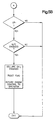
- Figs. 5A-5B are schematic illustrations, in flow chart format, of a preferred embodiment of the present invention.
- Figs. 6A-6B are schematic illustrations, in flow chart format, of an alternate embodiment of the present invention.
- compound transmission is used to designate a change-speed or change-gear transmission having a main transmission section and an auxiliary drive train unit, such as an auxiliary transmission section, connected in series whereby the selected gear reduction in the main transmission section may be compounded by further selected gear reduction in the auxiliary transmission section.
- upshift shall mean the shifting from a lower speed gear ratio to a higher speed gear ratio
- downshift shall mean the shifting from a higher speed gear ratio to a lower speed gear ratio.
- Figs. 1 and 1A illustrate a combined range-and-splitter-type compound transmission 10 which is especially well suited for control by the semi-automatic shift implementation control system/method of the present invention.
- Transmission 10 comprises a main transmission section 12 connected in series with an output and auxiliary transmission section 14 having both range- and splitter-type gearing.
- transmission 10 is housed within a single multi-piece housing 16 and includes an input shaft 18 driven by a prime mover, such as a diesel engine, through a selectively disengaged, normally engaged, master friction clutch.
- a prime mover such as a diesel engine
- the input shaft 18 carries an input gear 20 for driving at least one countershaft assembly 22.
- input gear 20 simultaneously drives a plurality of substantially identical main section countershaft assemblies at substantially identical rotational speeds.
- Each of the main section countershaft assemblies comprises a main section countershaft 24 supported by bearings 26 and 28 in housing 16 and is provided with main section countershaft gears 30, 32, 34, 36 and 38 fixed thereto.
- a plurality of main section drive or mainshaft gears 40, 42 and 44 surround the transmission mainshaft 46 and are selectively clutchable, one at a time, to the mainshaft 46 for rotation therewith by sliding clutch collars 48 and 50, as is well known in the art.
- Clutch collar 48 also may be utilized to clutch input gear 20 to the mainshaft 46 to provide a direct drive relationship between the input shaft 18 and the mainshaft 46.
- each of the main section mainshaft gears encircles the mainshaft 46 and is in continuous meshing engagement with and is floatingly supported by the associated countershaft gear groups, which mounting means and special advantages resulting therefrom are explained in greater detail in aforementioned U.S. Pats. No. 3,105,395 and 3,335,616.
- clutch collars 48 and 50 are axially positioned by means of shift forks or yokes 52 and 54, respectively, associated with a shift bar housing assembly 56, which may be of the multiple-shift-rail or single-shift-shaft type, as is known in the prior art, and which is manually controlled by a shift lever 57.
- Clutch collars 48 and 50 are, in the preferred embodiment, of the well-known, non-synchronized, double-acting jaw clutch type.
- Main section mainshaft gear 44 is the reverse gear and is in continuous meshing engagement with countershaft gears 38 by means of conventional intermediate idler gears 57 (see Fig. 1A).
- Main section countershaft gear 32 is provided for powering power takeoff devices and the like.
- Jaw clutches 48 and 50 are 3-position clutches in that they may be positioned in a centered axially non-displaced, non-engaged position, as illustrated, or in a fully rightwardly engaged or fully leftwardly engaged position.
- Auxiliary transmission section 14 is connected in series with main transmission section 12 and is of the 3-layer, 4-speed combined splitter/range type, as illustrated in aforementioned U.S. Pats. No. 4,754,665 and 5,390,561.
- Mainshaft 46 extends into the auxiliary section 14 and is journalled in the inward end of the output shaft 58, which extends from the rearward end of the transmission.
- Auxiliary transmission section 14 includes in the preferred embodiment thereof a plurality of substantially identical auxiliary countershaft assemblies 60 (see Fig. 1A), each comprising an auxiliary countershaft 62 supported by bearings 64 and 66 in housing 16 and carrying three auxiliary section countershaft gears 68, 70 and 72 fixed for rotation therewith.
- Auxiliary countershaft gears 68 are constantly meshed with and support auxiliary section splitter gear 74.
- Auxiliary countershaft gears 70 are constantly meshed with and support auxiliary section splitter/range gear 76 which surrounds the output shaft 58 at the end thereof adjacent the coaxial inner end of mainshaft 46.
- Auxiliary section countershaft gears 72 constantly mesh with and support auxiliary section range gear 78, which surrounds the output shaft 58.
- auxiliary section countershaft gears 68 and splitter gear 74 define a first gear layer
- auxiliary section countershaft gears 70 and splitter/range gear 76 define a second gear layer
- auxiliary section countershaft gears 72 and range gear 78 define a third layer, or gear group, of the combined splitter-and-range-type auxiliary transmission section 14.
- a sliding double-sided jaw clutch collar 80 is utilized to selectively couple either the splitter gear 74 or the splitter/range gear 76 to the mainshaft 46, while a 2-position synchronized clutch assembly 82 is utilized to selectively couple the splitter/range gear 76 or the range gear 78 to the output shaft 58.
- the structure and function of double-acting jaw clutch collar 80 is substantially identical to the structure and function of the sliding clutch collars 48 and 50 utilized in the main transmission section 12, and the function of double-acting synchronized clutch assembly 82 is substantially identical to the structure and function of prior art double-acting synchronized clutch assembly, examples of which may be seen by reference to U.S. Pats. No. 4,462,489; 4,125,179 and 2,667,955.
- the illustrated synchronized clutch assembly 82 is of the pin type described in aforementioned U.S. Pat. No. 4,462,489.
- the splitter jaw clutch 80 is a 2-sided or double-acting clutch assembly which may be selectively positioned in the rightwardmost or leftwardmost positions for engaging either gear 76 or gear 74, respectively, to the mainshaft 46.
- the splitter jaw clutch 80 is axially positioned by means of a shift fork 84 controlled by a 2-position piston actuator 86, which is operable by a driver selection switch (such as a button or the like) on the shift knob, as is known in the prior art.
- Two-position synchronized clutch assembly 82 also is a 2-position clutch which may be selectively positioned in either the rightwardmost or leftwardmost positions thereof for selectively clutching either gear 78 or 76, respectively, to output shaft 58.
- Clutch assembly 82 is positioned by means of a shift fork 88 operated by means of a 2-position piston device 90, the actuation and control of which will be described in greater detail below.
- auxiliary transmission section 14 is a 3-layer auxiliary section of the combined range-and-splitter type providing four selectable speeds or drive ratios between the input (mainshaft 46) and output (output shaft 58) thereof.
- the main section 12 provides a reverse and three potentially selectable forward speeds. However, one of the selectable main section forward gear ratios, the low speed gear ratios associated with mainshaft gear 42, is not utilized in the high range.
- transmission 10 is properly designated as a "(2+1)x(2)x(2)" type transmission providing nine or ten selectable forward speeds, depending upon the desirability and practicality of splitting the low gear ratio.
- clutch 82 the range clutch
- double-acting clutch collar 80, the splitter clutch is not required to be synchronized.
- splitter clutch 80 is located interposed between the main transmission section 12 and the output, it is considered to be an output splitter.
- the prior art shift pattern for shifting transmission 10 is schematically illustrated in Fig. 2. Divisions in the vertical direction at each gear lever position signify splitter shifts, while movement in the horizontal direction from the 3/4 and 5/6 leg of the "H" pattern to the 7/8 and 9/10 leg of the "H” pattern signifies a shift from the low range to the high range of the transmission.
- splitter shifting is accomplished in the usual manner by means of a vehicle operator- actuated splitter button or the like, usually a button located at the shift lever knob. Operation of the range clutch shifting assembly is an automatic response to movement of the gear shift lever between the central and rightwardmost legs of the shift pattern, as illustrated in Fig. 2.
- Range shift devices of this general type are known in the prior art, as may be seen by reference to aforementioned U.S. Pats. No. 3,429,202; 4,455,883; 4,561,325 and 4,663,725.
- the main section ratio steps should be generally equal
- the splitter step should be generally equal to the square root of the main section ratio steps
- N the number of main section ratio steps occurring in both ranges
- a range control valve assembly is provided to provide a signal to a slave valve 92, located at piston assembly 90, to shift the shift fork 88.
- At least the forward shifting of transmission 10 is semi-automatically implemented by the vehicular semi-automatic transmission system 100, illustrated in Fig. 3.
- a compound-type transmission 10 comprising a main section 12 coupled to an auxiliary section 14 controlled by the shift control system/method of the invention, is seen in Fig. 3.
- Main section 12 includes input shaft 18, which is operatively coupled to the drive or crank shaft of the vehicle engine 102 by manually controlled master clutch 104, and output shaft 58 of auxiliary section 14 is operatively coupled, commonly by means of a drive shaft, to the drive wheels of the vehicle (not shown).
- the change-gear ratios available from main transmission section 12 are manually selectable by positioning the shift lever 57 according to the shift pattern prescribed to engage the particular change gear ratio of main section 12 desired.
- manual synchronizing is not required and, as is done for driving an automotive synchronized transmission, the master clutch may be disengaged during shifting.
- the system will include means to sense an intent to shift and will automatically take actions to minimize or relieve torque-lock conditions, which will allow shifting without requiring master clutch disengagement, allowing an easier shift into main section neutral from the engaged main section ratio and further allowing required splitter shifts to be preselected for rapid completion upon a torque break and shift into neutral.
- the system 100 includes sensors 106 for sensing engine rotational speed (ES), 108 for sensing input shaft rotational speed (IS), and 110 for sensing output shaft rotational speed (OS) and providing signals indicative thereof.
- Engine 102 may be electronically controlled, including an electronic controller 112 communicating over an electronic data link (DL) operating under an industry standard protocol such as SAE J-1922, SAE J-1939, ISO 11898 or the like. If such a data link is present, sensors such as engine speed sensor 106 may be eliminated, as engine speed and other control parameters are typically available on such data links.
- Throttle position (driver demand) is a desirable parameter for selecting shifting points and in other control logic.
- a separate throttle position sensor 113 may be provided or throttle position (THL) may be sensed from the data link.
- a manual clutch pedal 115 controls the master clutch, and a sensor 114 provides a signal (CL) indicative of clutch-engaged or -disengaged condition. The condition of the clutch also may be determined by comparing engine speed to input shaft speed.
- a splitter actuator 116 is provided for operating the splitter clutch 82 in accordance with command output signals.
- the shift lever 57 has a knob 118 which contains sensing means or a button 120 by which a driver's intent to shift may be sensed.
- Sensor 122 provides a signal (ITS) indicative of the sensed presence or absence of the driver's intent to shift into neutral.
- ITS signal
- ITS signal
- a driver's control display unit 124 includes a graphic representation of the six-position shift pattern with individually lightable buttons or other display elements 126, 128, 130, 132, 134 and 136 representing each of the selectable engagement positions.
- the unit also includes a button 138 connected to toggle-type controls for selecting the high or low splitter range for start-from-stop splitter position selection. The selection will be indicated by lights 142 or 144.
- buttons or members will be provided for each ratio, as shown by elements 128A and 128B, for ratios "1" and "2,” respectively.
- the system includes a control unit 146, preferably a microprocessor-based control unit of the type illustrated in U.S. Pats. No. 4,595,986; 4,361,065 and 5,335,566, for receiving input signals and processing same according to predetermined logic rules to issue command output signals 150 to system actuators, such as the splitter section actuator 116, the engine controller 112 and the display unit 124.
- a separate system controller 146 may be provided, or the engine controller 112 communicating over an electronic data link may be utilized.
- the splitter actuator 116 is a 3-position device, allowing a selectable and maintainable splitter section neutral.
- the actuator is responsive to signals from controller 146, and splitter neutral is selectable only by the controller 146 and not by selector 119, if utilized.
- Other 3-position actuators also may be utilized.
- Forward dynamic splitter-only shifts such as third-to-fourth and fourth-to-third shifts, are automatically implemented without driver intervention.
- the ECU 146 upon sensing that a splitter shift is required, the ECU 146 will issue commands to the actuator 116 to bias the actuator toward neutral, and to engine controller 112 to minimize or break torque.
- the engagement is timed, in view of reaction times and shaft speeds and accelerations, to occur just off synchronous to prevent clutch butting.
- Automatic splitter shifting of this type is illustrated in aforementioned U.S. Pats. No. 4,722,248 and 5,435,212.
- splitter shifting may be automatically implemented in response to driver manipulation of selector 119.
- a main section neutral sensor 147 is provided to sense the neutral/not-neutral condition of main transmission section 12.
- ES SYNCHRO (OS x GR T ) - 45 RPM)
- the foregoing logic allows transmission engaged and neutral conditions to be determined on the basis of input and output shaft speeds without false engagement sensing caused by engine synchronizing for engagement of a target ratio.
- a lever upshift (with an automatic splitter downshift) is appropriate and the system, if requested by the driver, will semi-automatically inplement same.
- a lever downshift (with an automatic splitter upshift) is appropriate and the system, if requested by the driver, will semi-automatically implement same.
- splitter-only shifts (such as 3-4 and 4-3 shifts) are preferably automatically implemented, while lever shifts, with accompanying splitter shifts, require driver initiation and main section jaw clutch manipulation.
- the display unit 124 will inform the driver of the currently engaged ratio lever position and the lever position of the currently appropriate lever shift, if any.
- the lever position of the currently engaged ratio will be indicated by a steadily lighted button, while the lever position of the appropriate lever shift will be indicated by a flashing button.
- the 3/4 button 130 will be steadily lit, indicating that third or fourth gear is engaged and, as an upshift into fifth is appropriate, the 5/6 button 132 will flash.
- the driver may choose to remain in fourth or decide that a shift into fifth is desirable.
- the transmission may be shifted in the manner of a familiar automotive manual synchronized transmission wherein the master clutch 104 is manually disengaged during the shift procedure.
- the master clutch is disengaged, allowing the operator to manually shift lever 57 to a neutral position.
- main section 12 and the splitter clutch 80 are both disengaged, main shaft 46 is at a very low inertia and easily engaged in any forward ratio, regardless of speed differences across the engaging jaw clutch members.
- the appropriate splitter ratio low for fifth
- the transmission also may be shifted without master clutch manipulation.
- the 3/4 button will be extinguished, while the controller 146 issues commands to the engine controller to cause the engine and input shaft speeds to approach the synchronous values therefor, when the appropriate splitter shift is completed (in this example, a splitter shift from splitter-high to splitter-low).
- the operator may shift easily into the 5/6 lever position without the use of the clutch.
- the 5/6 button 132 will be lit in a steady manner.
- the shift knob 118 will include a sensor or an intent-to-shift button 120 by which the driver will indicate that he intends to initiate a lever shift sequence.
- the controller 146 Upon receiving the intent-to-shift signal (ITS), the controller 146 will issue commands to the engine controller 112 to relieve torque lock by fuel manipulations and to auxiliary section actuator 116 to preselect the required splitter shift. This will allow easy shifting from the engaged ratio (fourth) into neutral without operator throttle manipulation or clutch disengagement, as well as providing a rapid splitter shift. Engine manipulations to relieve torque lock without requiring clutch disengagement is described in greater detail in aforementioned U.S. Pats. No. 4,850,236 and 5,105,357. Preferably, if no lower shift is then appropriate, the intent-to-shift signal will not be acted upon.
- the system may inform the operator of when the engine speed is at or is approaching synchronous sufficiently to allow the lever to be moved into the target lever position. This may be by an audible alarm, a separate "okay-to-shift” light and/or simply changing the frequency of flashing the target lever position button. Alternatively, as shown in U.S. Pat. No. 4,023,443. Informing the operator may comprise preventing or inhibiting shifting until properly synchronous conditions exist. Also, instead of lighting an entire position button, such as the 3/4 lever position button 130, individually controlled, lighted buttons or the like may be provided for each ratio ( i.e. , a separately controlled display element for each of the two reverse and ten forward-speed ratios).
- Output speed (OS) is constantly monitored and, if speed changes cause a change in appropriate or “best gear” during a shift sequence, a new "best gear” will be indicated by a flashing button and will be synchronized for.
- the transmission 10 is provided with an input shaft brake 13, also commonly called an inertia brake, actuated by the controller 146.
- the input shaft brake 13 is utilized, as is well known, to rapidly decelerate the input shaft 18 and associated gearing for more rapid upshifting.
- This embodiment differs from the embodiment of Figs. 5A and 5B only during a lever upshift into a target gear ratio.
- the present invention is especially well suited to a splitter-type transmission or a combined splitter-and-range-type transmission with an automatic range shifting feature (see U.S. Pat. No. 5,000,060, the disclosure of which is incorporated herein by reference), as these types of transmissions utilize a minimal number of lever shifts for a given number of forward ratios.
- transmission 10 will have a limp-home mode of operation, allowing engagement of two, three or five wide ratio step forward speeds.
Landscapes
- Engineering & Computer Science (AREA)
- Mechanical Engineering (AREA)
- Chemical & Material Sciences (AREA)
- Combustion & Propulsion (AREA)
- General Engineering & Computer Science (AREA)
- Transportation (AREA)
- Automation & Control Theory (AREA)
- Control Of Transmission Device (AREA)
Applications Claiming Priority (2)
| Application Number | Priority Date | Filing Date | Title |
|---|---|---|---|
| US08/822,668 US5904068A (en) | 1996-04-30 | 1997-03-24 | Semi-automatic shift implementation with synchronized transmission emulation |
| US822668 | 1997-03-24 |
Publications (3)
| Publication Number | Publication Date |
|---|---|
| EP0867643A2 true EP0867643A2 (de) | 1998-09-30 |
| EP0867643A3 EP0867643A3 (de) | 1999-10-13 |
| EP0867643B1 EP0867643B1 (de) | 2002-10-16 |
Family
ID=25236648
Family Applications (1)
| Application Number | Title | Priority Date | Filing Date |
|---|---|---|---|
| EP98301873A Expired - Lifetime EP0867643B1 (de) | 1997-03-24 | 1998-03-12 | Halbautomatische Schaltdurchführung eines Splitterverbundgetriebes |
Country Status (3)
| Country | Link |
|---|---|
| US (1) | US5904068A (de) |
| EP (1) | EP0867643B1 (de) |
| DE (1) | DE69808685T2 (de) |
Cited By (5)
| Publication number | Priority date | Publication date | Assignee | Title |
|---|---|---|---|---|
| EP0992716A1 (de) * | 1998-09-08 | 2000-04-12 | Eaton Corporation | Eingriffskontrolle für ein servounterstütztes, manuell geschaltetes synchroniertes Splitter-Verbundgetriebe |
| EP1092894A3 (de) * | 1999-10-12 | 2004-01-07 | Eaton Corporation | Anfahrtssteuerung für ein servounterstütztes, manuell geschaltetes Splitter-Verbundgetriebe |
| WO2004018250A3 (de) * | 2002-08-21 | 2004-04-01 | Zahnradfabrik Friedrichshafen | Verfahren zum steuern eines antriebsst5ranges eines fahrzeugs |
| US7288040B2 (en) | 2002-08-21 | 2007-10-30 | Zf Friedrichshafen Ag | Method for controlling the drive train of a vehicle |
| WO2012156112A1 (de) * | 2011-05-16 | 2012-11-22 | Zf Friedrichshafen Ag | Verfahren zum bestimmen eines schaltablaufes eines übersetzungswechsels einer getriebeeinrichtung eines fahrzeugantriebsstranges |
Families Citing this family (19)
| Publication number | Priority date | Publication date | Assignee | Title |
|---|---|---|---|---|
| DE19639200C1 (de) * | 1996-09-25 | 1997-12-18 | Daimler Benz Ag | Automatisch gesteuerte Kupplung |
| US5904635A (en) | 1997-08-07 | 1999-05-18 | Eaton Corporation | Partially automated lever-shifted mechanical transmission system |
| DE19840082A1 (de) * | 1998-09-03 | 2000-03-09 | Zahnradfabrik Friedrichshafen | Verfahren zur Steuerung eines lastschaltbaren Mehrgang-Schiffsgetriebes |
| US6246941B1 (en) * | 1999-03-25 | 2001-06-12 | Zf Meritor, Llc | Method of synchronizing engine torque with vehicle torque load for accomplishing vehicle transmission shifting |
| US6128974A (en) * | 1999-09-03 | 2000-10-10 | Eaton Corporation | Start gear engagement control for controller-assisted, manually shifted, synchronized, compound transmission with splitter section |
| DE10012355A1 (de) * | 2000-03-14 | 2001-10-04 | Man Nutzfahrzeuge Ag | Verfahren zur Bestimmung des eingelegten Ganges bei Handschaltgetrieben in Nutzfahrzeugen |
| US6361473B1 (en) * | 2000-04-27 | 2002-03-26 | Eaton Corporation | System/method for synchronized shifting of a manually shifted transmission |
| US6364810B1 (en) * | 2000-08-08 | 2002-04-02 | Eaton Corporation | Automatic splitter control for manually shifted transmission |
| DE10045729C2 (de) * | 2000-09-15 | 2003-07-17 | Zf Sachs Ag | Stelleinrichtung |
| SE526642C2 (sv) * | 2004-02-17 | 2005-10-18 | Scania Cv Abp | Anordning samt förfarande för detekterande av växelläge i en motorväxellåda samt användning av en sådan anordning |
| DE202004009307U1 (de) * | 2004-06-11 | 2004-12-02 | Gaslock Gmbh | Vorrichtung zum Anzeigen des eingelegten Gangs |
| JP4434136B2 (ja) * | 2005-12-14 | 2010-03-17 | トヨタ自動車株式会社 | 自動変速機の異常判定装置 |
| US7468018B2 (en) * | 2006-03-06 | 2008-12-23 | Anthony Francis Radich | System and method for matching engine speed to vehicle speed with a manual transmission |
| FR2907746B1 (fr) * | 2006-10-30 | 2009-01-30 | Peugeot Citroen Automobiles Sa | Procede de determination du rapport qui est engage dans une boite de vitesses de vehicule automobile |
| US8306707B2 (en) | 2007-11-08 | 2012-11-06 | Parker-Hannifin Corporation | Transmission shifting with speed dither and torque dither |
| DE102009002206A1 (de) * | 2009-04-06 | 2010-10-14 | Zf Friedrichshafen Ag | Verfahren zum Betreiben eines Fahrzeugantriebsstranges |
| FR2954254B1 (fr) * | 2009-12-17 | 2012-03-09 | Peugeot Citroen Automobiles Sa | Procede et systeme de desaccouplement d'une machine electrique sur un train roulant de vehicule, notamment d'un vehicule automobile hybride |
| US9506509B1 (en) * | 2015-09-10 | 2016-11-29 | Ford Global Technologies, Llc | Clutch control using dither |
| US12511953B2 (en) * | 2024-03-29 | 2025-12-30 | Adeia Guides Inc. | Emulation of petrol-based vehicle packages in electric vehicles |
Citations (35)
| Publication number | Priority date | Publication date | Assignee | Title |
|---|---|---|---|---|
| US2667955A (en) | 1950-07-22 | 1954-02-02 | Clark Equipment Co | Synchronizer |
| US3105395A (en) | 1962-12-26 | 1963-10-01 | Eaton Mfg Co | Automotive device |
| US3335616A (en) | 1966-01-20 | 1967-08-15 | Eaton Yale & Towne | Twin countershaft with fixed main shaft |
| US3429202A (en) | 1965-08-19 | 1969-02-25 | Georges Camille Eugene Galiche | Gear boxes |
| US4023443A (en) | 1972-12-15 | 1977-05-17 | Nissan Motor Co., Ltd. | Transmission synchronizing mechanism |
| US4125179A (en) | 1977-07-25 | 1978-11-14 | Dana Corporation | Synchronizing device having spring pin thrust members |
| US4361065A (en) | 1978-11-20 | 1982-11-30 | Kimball International Inc. | Integrated central processor for electronic organ |
| US4428469A (en) | 1981-07-31 | 1984-01-31 | Eaton Corporation | Synchronizer spring pin |
| US4455883A (en) | 1980-11-14 | 1984-06-26 | Eaton Corporation | Combined shift control |
| US4462489A (en) | 1981-07-31 | 1984-07-31 | Eaton Corporation | Synchronizer spring pin |
| US4561325A (en) | 1983-10-20 | 1985-12-31 | Dana Corporation | Transmission and range box control |
| US4595986A (en) | 1984-10-09 | 1986-06-17 | Eaton Corporation | Method for control of automatic mechanical transmission system utilizing a microprocessor based electronic controller |
| US4663725A (en) | 1985-02-15 | 1987-05-05 | Thermo King Corporation | Microprocessor based control system and method providing better performance and better operation of a shipping container refrigeration system |
| US4722248A (en) | 1986-04-11 | 1988-02-02 | Eaton Corporation | Transmission shift control system |
| US4735109A (en) | 1981-07-27 | 1988-04-05 | Eaton Corporation | Semi-blocked transmission |
| US4754665A (en) | 1986-02-05 | 1988-07-05 | Eaton Corporation | Auxiliary transmission section |
| US4788889A (en) | 1987-03-19 | 1988-12-06 | Eaton Corporation | Mechanical transmission and control method therefor |
| US4850236A (en) | 1987-11-20 | 1989-07-25 | Eaton Corporation | Vehicle drive line shift control system and method |
| US4944197A (en) | 1989-06-07 | 1990-07-31 | Eaton Corporation | Resilient range interlock |
| US4989706A (en) | 1989-10-25 | 1991-02-05 | Eaton Corporation | Synchronizer |
| US5038627A (en) | 1990-04-25 | 1991-08-13 | Dana Corporation | Vehicle transmission with manually shifted lower gears and automatically shifted upper gears |
| US5105357A (en) | 1989-07-24 | 1992-04-14 | Eaton Corporation | Shift implementation control system and method for mechanical transmission system |
| US5193410A (en) | 1992-01-23 | 1993-03-16 | Eaton Corporation | Range section protection valve assembly |
| US5267636A (en) | 1991-04-12 | 1993-12-07 | Eaton Corporation | Synchronizer sliding clutch sleeve |
| US5335566A (en) | 1992-07-06 | 1994-08-09 | Eaton Corporation | Shift control method/system |
| US5390561A (en) | 1993-05-20 | 1995-02-21 | Eaton Corporation | Compound transmission |
| US5435212A (en) | 1992-10-30 | 1995-07-25 | Eaton Corporation | Semi-automatic shift implementation |
| US5523477A (en) | 1995-01-23 | 1996-06-04 | Merck & Co., Inc. | Process for the preparation of 1-(thiomethyl)-cyclopropaneacetic acid |
| US5569115A (en) | 1995-07-27 | 1996-10-29 | Rockwell International Corporation | Engine speed synchronization system for assisting in manual transmission shifting |
| US5573477A (en) | 1995-07-27 | 1996-11-12 | Rockwell International Corporation | Method and apparatus for assisting in shifting transmission to neutral |
| US5582558A (en) | 1995-07-27 | 1996-12-10 | Rockwell International Corporation | Combined system for assisting shifting of manual transmission |
| US5588516A (en) | 1993-12-27 | 1996-12-31 | Eaton Corporation | Synchronizer with self-energizing |
| US5682790A (en) | 1996-04-30 | 1997-11-04 | Eaton Corporation | Synchronizing and gear engagement sensing logic for automated mechanical transmission system |
| EP0805061A1 (de) | 1996-04-30 | 1997-11-05 | Eaton Corporation | Schaltabsichtvorrichtung für halbautomatische Schaltdurchführung |
| US5735771A (en) | 1996-04-30 | 1998-04-07 | Eaton Corporation | Semi-automatic shift implementation |
Family Cites Families (7)
| Publication number | Priority date | Publication date | Assignee | Title |
|---|---|---|---|---|
| JPS5576244A (en) * | 1978-12-04 | 1980-06-09 | Toyota Motor Corp | Selective control method of auxiliary change gear for automobile use |
| US4527447A (en) * | 1982-12-06 | 1985-07-09 | Eaton Corporation | Automatic mechanical transmission system |
| US5315900A (en) * | 1992-12-17 | 1994-05-31 | Eaton Corporation | Transmission control lever having cruise and engine brake control |
| US5425284A (en) * | 1993-09-07 | 1995-06-20 | Eaton Corporation | Automated mechanical transmission control system/method |
| US5413012A (en) * | 1993-09-07 | 1995-05-09 | Eaton Corporation | Variable synchronous window |
| US5679093A (en) * | 1995-07-27 | 1997-10-21 | Rockwell International Corporation | Engine speed retardation on transmission upshift |
| US5571059A (en) * | 1995-07-27 | 1996-11-05 | Rockwell International Corporation | Operator input system for gear shift assist mechanism |
-
1997
- 1997-03-24 US US08/822,668 patent/US5904068A/en not_active Expired - Lifetime
-
1998
- 1998-03-12 EP EP98301873A patent/EP0867643B1/de not_active Expired - Lifetime
- 1998-03-12 DE DE69808685T patent/DE69808685T2/de not_active Expired - Lifetime
Patent Citations (35)
| Publication number | Priority date | Publication date | Assignee | Title |
|---|---|---|---|---|
| US2667955A (en) | 1950-07-22 | 1954-02-02 | Clark Equipment Co | Synchronizer |
| US3105395A (en) | 1962-12-26 | 1963-10-01 | Eaton Mfg Co | Automotive device |
| US3429202A (en) | 1965-08-19 | 1969-02-25 | Georges Camille Eugene Galiche | Gear boxes |
| US3335616A (en) | 1966-01-20 | 1967-08-15 | Eaton Yale & Towne | Twin countershaft with fixed main shaft |
| US4023443A (en) | 1972-12-15 | 1977-05-17 | Nissan Motor Co., Ltd. | Transmission synchronizing mechanism |
| US4125179A (en) | 1977-07-25 | 1978-11-14 | Dana Corporation | Synchronizing device having spring pin thrust members |
| US4361065A (en) | 1978-11-20 | 1982-11-30 | Kimball International Inc. | Integrated central processor for electronic organ |
| US4455883A (en) | 1980-11-14 | 1984-06-26 | Eaton Corporation | Combined shift control |
| US4735109A (en) | 1981-07-27 | 1988-04-05 | Eaton Corporation | Semi-blocked transmission |
| US4428469A (en) | 1981-07-31 | 1984-01-31 | Eaton Corporation | Synchronizer spring pin |
| US4462489A (en) | 1981-07-31 | 1984-07-31 | Eaton Corporation | Synchronizer spring pin |
| US4561325A (en) | 1983-10-20 | 1985-12-31 | Dana Corporation | Transmission and range box control |
| US4595986A (en) | 1984-10-09 | 1986-06-17 | Eaton Corporation | Method for control of automatic mechanical transmission system utilizing a microprocessor based electronic controller |
| US4663725A (en) | 1985-02-15 | 1987-05-05 | Thermo King Corporation | Microprocessor based control system and method providing better performance and better operation of a shipping container refrigeration system |
| US4754665A (en) | 1986-02-05 | 1988-07-05 | Eaton Corporation | Auxiliary transmission section |
| US4722248A (en) | 1986-04-11 | 1988-02-02 | Eaton Corporation | Transmission shift control system |
| US4788889A (en) | 1987-03-19 | 1988-12-06 | Eaton Corporation | Mechanical transmission and control method therefor |
| US4850236A (en) | 1987-11-20 | 1989-07-25 | Eaton Corporation | Vehicle drive line shift control system and method |
| US4944197A (en) | 1989-06-07 | 1990-07-31 | Eaton Corporation | Resilient range interlock |
| US5105357A (en) | 1989-07-24 | 1992-04-14 | Eaton Corporation | Shift implementation control system and method for mechanical transmission system |
| US4989706A (en) | 1989-10-25 | 1991-02-05 | Eaton Corporation | Synchronizer |
| US5038627A (en) | 1990-04-25 | 1991-08-13 | Dana Corporation | Vehicle transmission with manually shifted lower gears and automatically shifted upper gears |
| US5267636A (en) | 1991-04-12 | 1993-12-07 | Eaton Corporation | Synchronizer sliding clutch sleeve |
| US5193410A (en) | 1992-01-23 | 1993-03-16 | Eaton Corporation | Range section protection valve assembly |
| US5335566A (en) | 1992-07-06 | 1994-08-09 | Eaton Corporation | Shift control method/system |
| US5435212A (en) | 1992-10-30 | 1995-07-25 | Eaton Corporation | Semi-automatic shift implementation |
| US5390561A (en) | 1993-05-20 | 1995-02-21 | Eaton Corporation | Compound transmission |
| US5588516A (en) | 1993-12-27 | 1996-12-31 | Eaton Corporation | Synchronizer with self-energizing |
| US5523477A (en) | 1995-01-23 | 1996-06-04 | Merck & Co., Inc. | Process for the preparation of 1-(thiomethyl)-cyclopropaneacetic acid |
| US5569115A (en) | 1995-07-27 | 1996-10-29 | Rockwell International Corporation | Engine speed synchronization system for assisting in manual transmission shifting |
| US5573477A (en) | 1995-07-27 | 1996-11-12 | Rockwell International Corporation | Method and apparatus for assisting in shifting transmission to neutral |
| US5582558A (en) | 1995-07-27 | 1996-12-10 | Rockwell International Corporation | Combined system for assisting shifting of manual transmission |
| US5682790A (en) | 1996-04-30 | 1997-11-04 | Eaton Corporation | Synchronizing and gear engagement sensing logic for automated mechanical transmission system |
| EP0805061A1 (de) | 1996-04-30 | 1997-11-05 | Eaton Corporation | Schaltabsichtvorrichtung für halbautomatische Schaltdurchführung |
| US5735771A (en) | 1996-04-30 | 1998-04-07 | Eaton Corporation | Semi-automatic shift implementation |
Non-Patent Citations (1)
| Title |
|---|
| "SAE paper 840307" |
Cited By (6)
| Publication number | Priority date | Publication date | Assignee | Title |
|---|---|---|---|---|
| EP0992716A1 (de) * | 1998-09-08 | 2000-04-12 | Eaton Corporation | Eingriffskontrolle für ein servounterstütztes, manuell geschaltetes synchroniertes Splitter-Verbundgetriebe |
| EP1092894A3 (de) * | 1999-10-12 | 2004-01-07 | Eaton Corporation | Anfahrtssteuerung für ein servounterstütztes, manuell geschaltetes Splitter-Verbundgetriebe |
| WO2004018250A3 (de) * | 2002-08-21 | 2004-04-01 | Zahnradfabrik Friedrichshafen | Verfahren zum steuern eines antriebsst5ranges eines fahrzeugs |
| US7288040B2 (en) | 2002-08-21 | 2007-10-30 | Zf Friedrichshafen Ag | Method for controlling the drive train of a vehicle |
| US7344475B2 (en) | 2002-08-21 | 2008-03-18 | Zf Friedrichshafen Ag | Method for controlling a drivetrain of a vehicle |
| WO2012156112A1 (de) * | 2011-05-16 | 2012-11-22 | Zf Friedrichshafen Ag | Verfahren zum bestimmen eines schaltablaufes eines übersetzungswechsels einer getriebeeinrichtung eines fahrzeugantriebsstranges |
Also Published As
| Publication number | Publication date |
|---|---|
| EP0867643A3 (de) | 1999-10-13 |
| DE69808685D1 (de) | 2002-11-21 |
| DE69808685T2 (de) | 2003-07-03 |
| US5904068A (en) | 1999-05-18 |
| EP0867643B1 (de) | 2002-10-16 |
Similar Documents
| Publication | Publication Date | Title |
|---|---|---|
| EP0805063B1 (de) | Halbautomatische Schaltdurchführung | |
| US6015366A (en) | Vehicular semi-automatic shift implementation system for lever-shifted, splitter-type, compound transmission with an intent-to-shift switch operable to cause automatic control of engine fueling and initiation of a splitter shift | |
| US5755639A (en) | Semi-automatic shift implementation with automatic splitter shifting | |
| EP0805062B1 (de) | Synchronisierung und Eingriffserfassung für automatische Getriebesysteme | |
| EP0867643B1 (de) | Halbautomatische Schaltdurchführung eines Splitterverbundgetriebes | |
| EP0896172B1 (de) | Teilautomatisiertes, handgeschaltetes Getriebe | |
| US5435212A (en) | Semi-automatic shift implementation | |
| US6461274B1 (en) | Automated transmission system control with zero engine flywheel torque determination | |
| EP0992716A1 (de) | Eingriffskontrolle für ein servounterstütztes, manuell geschaltetes synchroniertes Splitter-Verbundgetriebe | |
| EP0947739A2 (de) | Steuerung einer Bereichsschaltanordnung | |
| US6044721A (en) | Control for controller-assisted large backlash jaw clutches in main and auxiliary sections | |
| EP1092894A2 (de) | Anfahrtssteuerung für ein servounterstütztes, manuell geschaltetes Splitter-Verbundgetriebe | |
| EP0404352B1 (de) | Steuerungssystem/-verfahren zur Steuerung der Schaltung eines Reihenverbundgetriebes, Eingangswellen- und Hauptantriebswellen-Drehzahlsensoren benützend | |
| US6007455A (en) | Semi-automatic shift implementation with automatic engine control enable switch | |
| EP0576156B1 (de) | Verbessertes mechanisches semi-automatisches Getriebesystem | |
| EP1143172B1 (de) | Steuerung der Bereichsschaltung eines manuellen Verbundgetriebes | |
| US6997074B2 (en) | Prediction of destination gear for progressive shift feature | |
| US6840126B1 (en) | Automatic range up-shift control and method of operation | |
| CA2092463A1 (en) | Enhanced semi-automated mechanical transmission system | |
| MXPA98001485A (en) | Implementation of semi-automatic changes with automatic control switch of automatic mo | |
| GB2361036A (en) | Compound transmission with automatic range shift if incorrect gear shift is selected | |
| MXPA97003171A (en) | Semi-automatic implementation of change | |
| MXPA97003172A (en) | Semi-automatic implementation of change of attempt to change |
Legal Events
| Date | Code | Title | Description |
|---|---|---|---|
| PUAI | Public reference made under article 153(3) epc to a published international application that has entered the european phase |
Free format text: ORIGINAL CODE: 0009012 |
|
| AK | Designated contracting states |
Kind code of ref document: A2 Designated state(s): DE FR GB IT |
|
| AX | Request for extension of the european patent |
Free format text: AL;LT;LV;MK;RO;SI |
|
| PUAL | Search report despatched |
Free format text: ORIGINAL CODE: 0009013 |
|
| AK | Designated contracting states |
Kind code of ref document: A3 Designated state(s): AT BE CH DE DK ES FI FR GB GR IE IT LI LU MC NL PT SE |
|
| AX | Request for extension of the european patent |
Free format text: AL;LT;LV;MK;RO;SI |
|
| AKX | Designation fees paid |
Free format text: DE FR GB IT |
|
| 17P | Request for examination filed |
Effective date: 20000419 |
|
| GRAG | Despatch of communication of intention to grant |
Free format text: ORIGINAL CODE: EPIDOS AGRA |
|
| 17Q | First examination report despatched |
Effective date: 20020204 |
|
| GRAG | Despatch of communication of intention to grant |
Free format text: ORIGINAL CODE: EPIDOS AGRA |
|
| GRAH | Despatch of communication of intention to grant a patent |
Free format text: ORIGINAL CODE: EPIDOS IGRA |
|
| GRAH | Despatch of communication of intention to grant a patent |
Free format text: ORIGINAL CODE: EPIDOS IGRA |
|
| GRAA | (expected) grant |
Free format text: ORIGINAL CODE: 0009210 |
|
| AK | Designated contracting states |
Kind code of ref document: B1 Designated state(s): DE FR GB IT |
|
| REG | Reference to a national code |
Ref country code: GB Ref legal event code: FG4D |
|
| REF | Corresponds to: |
Ref document number: 69808685 Country of ref document: DE Date of ref document: 20021121 |
|
| ET | Fr: translation filed | ||
| PLBE | No opposition filed within time limit |
Free format text: ORIGINAL CODE: 0009261 |
|
| STAA | Information on the status of an ep patent application or granted ep patent |
Free format text: STATUS: NO OPPOSITION FILED WITHIN TIME LIMIT |
|
| 26N | No opposition filed |
Effective date: 20030717 |
|
| PGFP | Annual fee paid to national office [announced via postgrant information from national office to epo] |
Ref country code: FR Payment date: 20050302 Year of fee payment: 8 |
|
| PGFP | Annual fee paid to national office [announced via postgrant information from national office to epo] |
Ref country code: IT Payment date: 20060331 Year of fee payment: 9 |
|
| REG | Reference to a national code |
Ref country code: FR Ref legal event code: ST Effective date: 20061130 |
|
| PG25 | Lapsed in a contracting state [announced via postgrant information from national office to epo] |
Ref country code: FR Free format text: LAPSE BECAUSE OF NON-PAYMENT OF DUE FEES Effective date: 20060331 |
|
| PG25 | Lapsed in a contracting state [announced via postgrant information from national office to epo] |
Ref country code: IT Free format text: LAPSE BECAUSE OF NON-PAYMENT OF DUE FEES Effective date: 20070312 |
|
| PGFP | Annual fee paid to national office [announced via postgrant information from national office to epo] |
Ref country code: DE Payment date: 20140331 Year of fee payment: 17 |
|
| PGFP | Annual fee paid to national office [announced via postgrant information from national office to epo] |
Ref country code: GB Payment date: 20140225 Year of fee payment: 17 |
|
| REG | Reference to a national code |
Ref country code: DE Ref legal event code: R119 Ref document number: 69808685 Country of ref document: DE |
|
| GBPC | Gb: european patent ceased through non-payment of renewal fee |
Effective date: 20150312 |
|
| PG25 | Lapsed in a contracting state [announced via postgrant information from national office to epo] |
Ref country code: DE Free format text: LAPSE BECAUSE OF NON-PAYMENT OF DUE FEES Effective date: 20151001 Ref country code: GB Free format text: LAPSE BECAUSE OF NON-PAYMENT OF DUE FEES Effective date: 20150312 |