EP0867663A1 - Dichtung für Kochmulde - Google Patents
Dichtung für Kochmulde Download PDFInfo
- Publication number
- EP0867663A1 EP0867663A1 EP98400697A EP98400697A EP0867663A1 EP 0867663 A1 EP0867663 A1 EP 0867663A1 EP 98400697 A EP98400697 A EP 98400697A EP 98400697 A EP98400697 A EP 98400697A EP 0867663 A1 EP0867663 A1 EP 0867663A1
- Authority
- EP
- European Patent Office
- Prior art keywords
- seal
- hob
- frame
- branch
- extension
- Prior art date
- Legal status (The legal status is an assumption and is not a legal conclusion. Google has not performed a legal analysis and makes no representation as to the accuracy of the status listed.)
- Granted
Links
- 238000010411 cooking Methods 0.000 title claims abstract description 29
- 238000007789 sealing Methods 0.000 title description 9
- 239000011324 bead Substances 0.000 claims description 6
- 238000011144 upstream manufacturing Methods 0.000 claims description 2
- 230000000284 resting effect Effects 0.000 claims 1
- 238000001125 extrusion Methods 0.000 abstract description 2
- 238000000465 moulding Methods 0.000 abstract description 2
- 238000003825 pressing Methods 0.000 description 6
- 238000009434 installation Methods 0.000 description 5
- 239000007788 liquid Substances 0.000 description 5
- 239000002245 particle Substances 0.000 description 5
- 239000007787 solid Substances 0.000 description 5
- 230000008901 benefit Effects 0.000 description 3
- 238000000034 method Methods 0.000 description 3
- 230000006978 adaptation Effects 0.000 description 2
- 238000004026 adhesive bonding Methods 0.000 description 2
- 230000004888 barrier function Effects 0.000 description 2
- 230000000694 effects Effects 0.000 description 2
- 229920001296 polysiloxane Polymers 0.000 description 2
- 238000005520 cutting process Methods 0.000 description 1
- 230000007547 defect Effects 0.000 description 1
- 238000001035 drying Methods 0.000 description 1
- 239000000428 dust Substances 0.000 description 1
- 239000011521 glass Substances 0.000 description 1
- 239000002241 glass-ceramic Substances 0.000 description 1
- 238000010438 heat treatment Methods 0.000 description 1
- 230000006698 induction Effects 0.000 description 1
- 238000004519 manufacturing process Methods 0.000 description 1
- 239000000463 material Substances 0.000 description 1
- 238000006116 polymerization reaction Methods 0.000 description 1
- 239000011800 void material Substances 0.000 description 1
Images




Classifications
-
- F—MECHANICAL ENGINEERING; LIGHTING; HEATING; WEAPONS; BLASTING
- F24—HEATING; RANGES; VENTILATING
- F24C—DOMESTIC STOVES OR RANGES ; DETAILS OF DOMESTIC STOVES OR RANGES, OF GENERAL APPLICATION
- F24C15/00—Details
- F24C15/10—Tops, e.g. hot plates; Rings
- F24C15/108—Mounting of hot plate on worktop
Definitions
- the present invention relates to a hob comprising a hob, a frame and a housing assembled in such a way waterproof and comprising a device for sealing the table cooking with a support.
- the present invention also relates to a waterproof assembly process of the hob.
- the hob generally has several elements such as for example a hob, a frame and a housing. he it is necessary to provide a seal comparable to that described previously. This tightness is generally obtained by gluing.
- the present object of the invention is to simplify the mounting of the various elements mentioned previously between them and reduce the cost related to sealing.
- the hob has a cooking, a frame and a casing assembled in a sealed manner and comprising a device for sealing the hob with a support.
- the hob is characterized in that it further comprises a seal which seals the assembly between the hob, the frame and the casing and in that said device comprises an extension of the seal
- FIG. 1 In this figure, in reference 1 is represented a cooking plan by example in glass or glass ceramic.
- This hob 1 has for example the shape of a plate limited by two planes 2 and 3 parallel. Plan 2 forms the upper surface of the plate and plane 3 the lower surface.
- Plan 2 forms the upper surface of the plate and plane 3 the lower surface.
- This plate generally square or rectangular is also limited by four plane surfaces 4 perpendicular to the two planes 2 and 3 and forming the sides of the hob.
- Cooking surface 1 is shown in section partial.
- the cutting plane is perpendicular to surfaces 2, 3 and has a side 4.
- a frame 5 surrounds the hob 1 along the sides 4.
- the frame 5 has a massive part 6 limited mainly by two surfaces substantially flat, one 7 follows the sides 4 in parallel and is close thereto, the other 8 is substantially in the extension of the plane 3.
- the part massive 6 is also limited by a surface 9 which can be arbitrary and which for example has an aesthetic function. In figure 1 it is represented by an arc of a circle delimited by surfaces 7 and 8.
- the frame 5 also has two flanges which extend the massive part 6 for example tangentially to the surface 9.
- the first flange 10 bears on the plane 2 of cooking surface 1, the second edge 11 descends lower than the plane 3 of the cooking surface 1. In section, the edges 10 and 11 have the form of fingers.
- the hob also has a housing 12.
- This housing closes the underside of the cooktop, it contains, among other elements of radiant or induction heating, for example.
- the casing 12 can be produced in several mechanical parts. In Figure 1, only the part is represented of the housing in contact with the cooking surface 1 and the frame 5. This part of the casing 12 is for example a profile whose cross section shown in FIG. 1 has the shape of a square with two branches. A first branch 13 is substantially parallel to the plane 3 of the cooking surface 1 and to the surface 8 of the frame 5. A second branch 14 is perpendicular to the first branch and descends under plane 3 of cooking surface 1.
- seal 15 is made of flexible material by example based on silicone in order to mitigate the effects of possible defects in shape or positions of the parts with which it is in contact.
- a first level concerns the tightness of the inside of the table cooking compared to the outside. More specifically, it is to avoid that solid or liquid particles cannot penetrate inside the Cooktop.
- This first level is obtained by means of a first zone 16 of the seal 15. This zone is for example flat and is positioned between the first branch 13 of the housing square 12 and the two surfaces 3 and 8, the plane 3 belonging to the cooking surface 1 and the surface 8 belonging to frame 5.
- the seal is then pressed to ensure a sufficient barrier to solid or liquid particles using any means adequate mechanical cannot be dismantled, for example gluing or stapling or removable, for example using one or more screw, one or more clips.
- a second level concerns the seal between the table cooking and a support 17 on which the hob is placed.
- This support 17 is for example the worktop of an equipped kitchen.
- the support 17 comprises for example an opening of dimensions close to dimensions separating the flat surfaces 4 delimiting the cooking surface 1.
- the dimensions of this opening are sufficient to let the second branch 14 of the housing 12.
- the first branch 13 of the housing 12 comes to bear on the upper face 19 of the work surface 17. As with the first level of tightness, this is to prevent solid or liquid particles cannot enter between the hob and the work plan 17.
- the seal 15 is extended between branch 13 of the housing square 12 and the flange 11 of the box 5. This extension is marked 18.
- Another advantage linked to the invention is obtained when using means for pressing the seal 15 such as screws or clips. These means allow to get rid of the collage usually used.
- the collage has effect the inconvenience of disrupting the manufacturing cycle of the hob because of the polymerization or drying times to be observed.
- Another advantage linked to the invention is the possibility of laying the hob directly on the worktop and squeeze the extension 18 of seal 15 with the own weight of the hob. This considerably simplifies the installation of the hob by example in a domestic kitchen. We can do without all additional seals. However, it is still possible to fix the cooking on the work surface by means of a removable device such as for example several screws.
- FIG. 2 represents a variant of the process presented in FIG. 1 for which the rim 10 of the frame 5 has at its end a protrusion 30 approaching the cooking surface 1.
- This protrusion has for the function of producing between the frame 5 and the hob 1 a additional sealing upstream at the first sealing level described in figure 1. This additional sealing mainly prevents dust.
- Figure 3 shows the plane 3 of the cooking surface 1 substantially offset from the surface 8 of the frame 5.
- the offset is taken up by joint 15 which has a different thickness under the surface 8.
- This particular form of joint finds its usefulness when wish to use a single frame 5 with 1 thick hobs different or when you want to use a single hob 1 with several frames 5 of different dimensions.
- the dimensions of the seal 15 can be adapted.
- Figure 3 shows a thicker seal under the frame 5 than under the hob 1, we can heard realize the opposite, namely a thicker joint under the plane of cooking 1 only under frame 5 when the dimensions of frame 5 and the plan 1 require it.
- a seal 15 having a shape adapted to the shapes of all the parts with which it is in contact, such as hob 1, the frame 5, the housing 12, and the worktop 17.
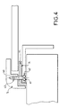
- Figure 4 shows the different elements of Figure 1 in y adding a screw 40 ensuring the pressing of the seal 15.
- the axis of this screw is perpendicular to the area 16 of the joint 15.
- This screw has a head 41 embedded in a counterbore 42 produced in branch 13 of the housing angle 12.
- the screw 40 is screwed into a tapped hole 43 made in frame 5. It it is understood that it is possible to install several screws 40 and that in this case you have to adapt the number of screws 40 to the dimensions of the table cooking.
- Figure 5 shows the elements of Figure 4 by modifying the extension 18 of the seal 15.
- This extension 18 comprises, in FIG. 5, two lips 50 coming to crash on the upper face 19 of the work surface 17.
- the two lips are symmetrical, one is crushed towards inside the hob, the other in the opposite direction.
- Figure 6 shows the elements of Figure 4 by modifying the extension 18.
- the extension 18 extends, FIG. 6, under the head 41 of the screw 40 and ends with two lips 60 both crushed on the face upper 19 of work plan 17, towards the inside of the table cooking.
- the first zone 16 of the seal 15 is modified.
- She comprises, in this figure, two beads 61 oriented upwards. In section, the beads 61 have the shape of domes. These two beads 61 are pressed against the hob 3 of the hob 1.
- Figure 7 shows the different elements of Figure 1 in y adding a screw 40 ensuring the pressing of the seal 15.
- the axis of this screw is perpendicular to the area 16 of the seal 15.
- the body of the screw 40 passes through a smooth hole drilled in branch 13 of the housing bracket 12.
- the screw 40 is screwed into a threaded hole 43 made in frame 5.
- the screw 40 has a head 41; this head 41 is located below the branch 13 and forms there a prominence.
- the extension 18 of the seal 15 extends under the head 41 of the screw 40.
- the end 70 of the extension 18 comes into contact with the branch 13.
- Under the head 41, the extension 18 has a double wall in the middle of which is a void 71.
- Figures 3, 5, 6 and 7 show several arrangements of the seal 15 given by way of example.
- This seal 15 can be produced by various embodiments such as for example molding or extrusion. These embodiments offer great freedom of possible forms that can use for example to adapt to the dimensions and shapes of parts between which the seal 15 is located or to locally adapt the elasticity of the joint. More specifically, Figures 5 and 6 show seals comprising lips 50 and 60 and / or beads 61. These layouts (lips or domes) are examples of shapes improving the tightness of the assembly. Lips 50 and 60 and the beads 61 have been represented in pairs, it is understood that their numbers are not given as an example.
Landscapes
- Engineering & Computer Science (AREA)
- Chemical & Material Sciences (AREA)
- Combustion & Propulsion (AREA)
- Mechanical Engineering (AREA)
- General Engineering & Computer Science (AREA)
- Gasket Seals (AREA)
- Cookers (AREA)
Applications Claiming Priority (2)
| Application Number | Priority Date | Filing Date | Title |
|---|---|---|---|
| FR9703611 | 1997-03-25 | ||
| FR9703611A FR2761461B1 (fr) | 1997-03-25 | 1997-03-25 | Etancheite d'une table de cuisson |
Publications (2)
| Publication Number | Publication Date |
|---|---|
| EP0867663A1 true EP0867663A1 (de) | 1998-09-30 |
| EP0867663B1 EP0867663B1 (de) | 2002-06-19 |
Family
ID=9505148
Family Applications (1)
| Application Number | Title | Priority Date | Filing Date |
|---|---|---|---|
| EP19980400697 Expired - Lifetime EP0867663B1 (de) | 1997-03-25 | 1998-03-25 | Dichtung für Kochmulde |
Country Status (3)
| Country | Link |
|---|---|
| EP (1) | EP0867663B1 (de) |
| DE (1) | DE69806082T2 (de) |
| FR (1) | FR2761461B1 (de) |
Cited By (2)
| Publication number | Priority date | Publication date | Assignee | Title |
|---|---|---|---|---|
| EP2144012A1 (de) * | 2008-07-09 | 2010-01-13 | Electrolux Home Products Corporation N.V. | Kochfeldanordnung mit Einbaukochfeldplatte |
| EP3943817A1 (de) * | 2020-07-24 | 2022-01-26 | E.G.O. Elektro-Gerätebau GmbH | Herd |
Families Citing this family (1)
| Publication number | Priority date | Publication date | Assignee | Title |
|---|---|---|---|---|
| DE102004048352B4 (de) * | 2004-10-01 | 2010-05-12 | Teka Küchentechnik GmbH | Haltevorrichtung, ausgebildet zur Halterung einer Kochplatte aus Glaskeramik eines Kochfeldes |
Citations (3)
| Publication number | Priority date | Publication date | Assignee | Title |
|---|---|---|---|---|
| DE3227058A1 (de) * | 1982-07-20 | 1984-01-26 | Licentia Patent-Verwaltungs-Gmbh, 6000 Frankfurt | Einbaukochflaeche aus glaskeramik |
| DE4202807C1 (de) * | 1992-01-31 | 1993-03-04 | Prometheus Ag Werk Murten, Murten, Ch | |
| DE4329956A1 (de) * | 1993-09-04 | 1995-03-09 | Schott Glaswerke | Anordnung zur Halterung eines Einbaukochfeldes |
-
1997
- 1997-03-25 FR FR9703611A patent/FR2761461B1/fr not_active Expired - Fee Related
-
1998
- 1998-03-25 EP EP19980400697 patent/EP0867663B1/de not_active Expired - Lifetime
- 1998-03-25 DE DE1998606082 patent/DE69806082T2/de not_active Expired - Fee Related
Patent Citations (3)
| Publication number | Priority date | Publication date | Assignee | Title |
|---|---|---|---|---|
| DE3227058A1 (de) * | 1982-07-20 | 1984-01-26 | Licentia Patent-Verwaltungs-Gmbh, 6000 Frankfurt | Einbaukochflaeche aus glaskeramik |
| DE4202807C1 (de) * | 1992-01-31 | 1993-03-04 | Prometheus Ag Werk Murten, Murten, Ch | |
| DE4329956A1 (de) * | 1993-09-04 | 1995-03-09 | Schott Glaswerke | Anordnung zur Halterung eines Einbaukochfeldes |
Cited By (2)
| Publication number | Priority date | Publication date | Assignee | Title |
|---|---|---|---|---|
| EP2144012A1 (de) * | 2008-07-09 | 2010-01-13 | Electrolux Home Products Corporation N.V. | Kochfeldanordnung mit Einbaukochfeldplatte |
| EP3943817A1 (de) * | 2020-07-24 | 2022-01-26 | E.G.O. Elektro-Gerätebau GmbH | Herd |
Also Published As
| Publication number | Publication date |
|---|---|
| DE69806082T2 (de) | 2003-02-13 |
| DE69806082D1 (de) | 2002-07-25 |
| FR2761461B1 (fr) | 1999-06-11 |
| FR2761461A1 (fr) | 1998-10-02 |
| EP0867663B1 (de) | 2002-06-19 |
Similar Documents
| Publication | Publication Date | Title |
|---|---|---|
| FR2636308A1 (fr) | Couvercle obturateur en matiere plastique, notamment pour obturer un orifice pratique dans un support | |
| FR2568226A1 (fr) | Couvercle de fermeture | |
| FR2509343A1 (fr) | Regard de visite pour canalisations d'assainissement | |
| EP0867663B1 (de) | Dichtung für Kochmulde | |
| FR2695287A1 (fr) | Appareil électrique, en particulier appareil de branchement et de commande pour véhicules à moteur. | |
| FR2831384A1 (fr) | Garniture pour l'etancheite d'un intervalle existant entre deux parties de boitier a etancheifier et boitier d'un appareil de commande d'un vehicule automobile | |
| EP0315520B1 (de) | Beleuchtungsvorrichtung mit Leuchtstoff-Röhrenlampen | |
| FR2832440A1 (fr) | Procede de fixation d'une vasque a un plan recepteur et dispositif ainsi obtenu | |
| EP0117812B1 (de) | Dichtungsscheibe für Elektronikablegetisch für Flugzeug | |
| FR2487953A1 (fr) | Dispositif de protection temporaire pour tables de cuisson | |
| FR2934140A1 (fr) | Couvercle d'appareil electromenager de cuisson comportant un sous-ensemble de filtration | |
| FR2659427A1 (fr) | Raccordement d'un dispositif de ventilation a un conduit exterieur. | |
| FR2778796A1 (fr) | Boitier a bornes de moteur | |
| FR2688566A1 (fr) | Dispositif d'etancheite pour un rebord de boitier. | |
| EP0641975B1 (de) | Flüssigkeitssammler für Kochmulde | |
| FR2732826A1 (fr) | Boitier pour appareillage electrique | |
| FR2675778A1 (fr) | Dispositif de fixation d'un couvercle sur une boite d'emballage en matiere plastique. | |
| EP3255995A1 (de) | Abgedichtete zerlegbare form zur lebensmittelzubereitung | |
| EP0483056B1 (de) | Rahmen für Verkleidungs- oder Fenster-Paneel | |
| FR3001473A1 (fr) | Ensemble modulaire pour evier | |
| FR2783775A1 (fr) | Corps de support pour lampes d'eclairage de la plaque d'immatriculation de vehicules automobiles | |
| EP0802375B1 (de) | Vorrichtung zur Klebeverbindung eines Glaselements | |
| LU82914A1 (fr) | Luminaire en nid d'abeilles avec corps entourant formant ceinture | |
| FR2703114A1 (fr) | Dispositif d'assemblage d'au moins deux plaques, notamment en tôle mince. | |
| EP0329573B1 (de) | Vorrichtung zum Befestigen von einzel- oder mehrschaligen Kuppeln, insbesondere Beleuchtungs- oder Lüftungskuppeln |
Legal Events
| Date | Code | Title | Description |
|---|---|---|---|
| PUAI | Public reference made under article 153(3) epc to a published international application that has entered the european phase |
Free format text: ORIGINAL CODE: 0009012 |
|
| AK | Designated contracting states |
Kind code of ref document: A1 Designated state(s): DE FR IT NL |
|
| AX | Request for extension of the european patent |
Free format text: AL;LT;LV;MK;RO;SI |
|
| 17P | Request for examination filed |
Effective date: 19990316 |
|
| AKX | Designation fees paid |
Free format text: DE FR IT NL |
|
| GRAG | Despatch of communication of intention to grant |
Free format text: ORIGINAL CODE: EPIDOS AGRA |
|
| 17Q | First examination report despatched |
Effective date: 20010709 |
|
| GRAG | Despatch of communication of intention to grant |
Free format text: ORIGINAL CODE: EPIDOS AGRA |
|
| GRAH | Despatch of communication of intention to grant a patent |
Free format text: ORIGINAL CODE: EPIDOS IGRA |
|
| GRAH | Despatch of communication of intention to grant a patent |
Free format text: ORIGINAL CODE: EPIDOS IGRA |
|
| GRAA | (expected) grant |
Free format text: ORIGINAL CODE: 0009210 |
|
| AK | Designated contracting states |
Kind code of ref document: B1 Designated state(s): DE FR IT NL |
|
| REF | Corresponds to: |
Ref document number: 69806082 Country of ref document: DE Date of ref document: 20020725 |
|
| PLBE | No opposition filed within time limit |
Free format text: ORIGINAL CODE: 0009261 |
|
| STAA | Information on the status of an ep patent application or granted ep patent |
Free format text: STATUS: NO OPPOSITION FILED WITHIN TIME LIMIT |
|
| 26N | No opposition filed |
Effective date: 20030320 |
|
| REG | Reference to a national code |
Ref country code: FR Ref legal event code: TP Ref country code: FR Ref legal event code: CD Ref country code: FR Ref legal event code: CA |
|
| NLS | Nl: assignments of ep-patents |
Owner name: COMPAGNIE EUROPEENNE DE FABRICATION D'ENCEINTES MI Effective date: 20071018 Owner name: BRANDT INDUSTRIES Effective date: 20071018 |
|
| NLT1 | Nl: modifications of names registered in virtue of documents presented to the patent office pursuant to art. 16 a, paragraph 1 |
Owner name: BRANDT COOKING |
|
| PGFP | Annual fee paid to national office [announced via postgrant information from national office to epo] |
Ref country code: NL Payment date: 20080327 Year of fee payment: 11 |
|
| PGFP | Annual fee paid to national office [announced via postgrant information from national office to epo] |
Ref country code: DE Payment date: 20080411 Year of fee payment: 11 |
|
| PGFP | Annual fee paid to national office [announced via postgrant information from national office to epo] |
Ref country code: IT Payment date: 20080331 Year of fee payment: 11 |
|
| NLV4 | Nl: lapsed or anulled due to non-payment of the annual fee |
Effective date: 20091001 |
|
| PG25 | Lapsed in a contracting state [announced via postgrant information from national office to epo] |
Ref country code: DE Free format text: LAPSE BECAUSE OF NON-PAYMENT OF DUE FEES Effective date: 20091001 |
|
| PG25 | Lapsed in a contracting state [announced via postgrant information from national office to epo] |
Ref country code: NL Free format text: LAPSE BECAUSE OF NON-PAYMENT OF DUE FEES Effective date: 20091001 |
|
| PG25 | Lapsed in a contracting state [announced via postgrant information from national office to epo] |
Ref country code: IT Free format text: LAPSE BECAUSE OF NON-PAYMENT OF DUE FEES Effective date: 20090325 |
|
| REG | Reference to a national code |
Ref country code: FR Ref legal event code: CD Owner name: FAGORBRANDT SAS, FR Effective date: 20110826 |
|
| PGFP | Annual fee paid to national office [announced via postgrant information from national office to epo] |
Ref country code: FR Payment date: 20120327 Year of fee payment: 15 |
|
| REG | Reference to a national code |
Ref country code: FR Ref legal event code: ST Effective date: 20131129 |
|
| PG25 | Lapsed in a contracting state [announced via postgrant information from national office to epo] |
Ref country code: FR Free format text: LAPSE BECAUSE OF NON-PAYMENT OF DUE FEES Effective date: 20130402 |