EP0867664A2 - Raumtemperierungssystem - Google Patents
Raumtemperierungssystem Download PDFInfo
- Publication number
- EP0867664A2 EP0867664A2 EP98105251A EP98105251A EP0867664A2 EP 0867664 A2 EP0867664 A2 EP 0867664A2 EP 98105251 A EP98105251 A EP 98105251A EP 98105251 A EP98105251 A EP 98105251A EP 0867664 A2 EP0867664 A2 EP 0867664A2
- Authority
- EP
- European Patent Office
- Prior art keywords
- room
- temperature control
- control system
- room temperature
- partition
- Prior art date
- Legal status (The legal status is an assumption and is not a legal conclusion. Google has not performed a legal analysis and makes no representation as to the accuracy of the status listed.)
- Withdrawn
Links
- 230000028016 temperature homeostasis Effects 0.000 title 1
- 238000005192 partition Methods 0.000 claims description 52
- 230000005855 radiation Effects 0.000 claims description 9
- 239000012774 insulation material Substances 0.000 claims description 4
- 239000002969 artificial stone Substances 0.000 claims description 3
- 238000001816 cooling Methods 0.000 claims description 3
- XLYOFNOQVPJJNP-UHFFFAOYSA-N water Substances O XLYOFNOQVPJJNP-UHFFFAOYSA-N 0.000 claims description 3
- 238000000926 separation method Methods 0.000 claims description 2
- 230000009194 climbing Effects 0.000 claims 1
- 238000009423 ventilation Methods 0.000 claims 1
- 239000006163 transport media Substances 0.000 abstract description 3
- 239000011796 hollow space material Substances 0.000 abstract 3
- 238000005496 tempering Methods 0.000 abstract 2
- 238000010438 heat treatment Methods 0.000 description 32
- 239000000463 material Substances 0.000 description 5
- 239000004927 clay Substances 0.000 description 4
- 238000013461 design Methods 0.000 description 4
- 238000005253 cladding Methods 0.000 description 3
- 238000009833 condensation Methods 0.000 description 3
- 230000005494 condensation Effects 0.000 description 3
- 230000001419 dependent effect Effects 0.000 description 3
- 238000009413 insulation Methods 0.000 description 3
- 239000004579 marble Substances 0.000 description 3
- 239000002609 medium Substances 0.000 description 3
- 230000036642 wellbeing Effects 0.000 description 3
- 238000004378 air conditioning Methods 0.000 description 2
- 239000000428 dust Substances 0.000 description 2
- 230000000694 effects Effects 0.000 description 2
- 230000006870 function Effects 0.000 description 2
- 239000010440 gypsum Substances 0.000 description 2
- 229910052602 gypsum Inorganic materials 0.000 description 2
- 238000012546 transfer Methods 0.000 description 2
- 238000004026 adhesive bonding Methods 0.000 description 1
- 230000000172 allergic effect Effects 0.000 description 1
- 208000010668 atopic eczema Diseases 0.000 description 1
- 230000015572 biosynthetic process Effects 0.000 description 1
- 238000006243 chemical reaction Methods 0.000 description 1
- 230000000295 complement effect Effects 0.000 description 1
- 238000010276 construction Methods 0.000 description 1
- 230000010259 detection of temperature stimulus Effects 0.000 description 1
- 238000011161 development Methods 0.000 description 1
- 230000018109 developmental process Effects 0.000 description 1
- 238000001035 drying Methods 0.000 description 1
- 230000007613 environmental effect Effects 0.000 description 1
- 239000004744 fabric Substances 0.000 description 1
- 230000002349 favourable effect Effects 0.000 description 1
- 238000003754 machining Methods 0.000 description 1
- 238000004519 manufacturing process Methods 0.000 description 1
- 238000005259 measurement Methods 0.000 description 1
- 238000000034 method Methods 0.000 description 1
- 238000010422 painting Methods 0.000 description 1
- 239000002245 particle Substances 0.000 description 1
- 239000002994 raw material Substances 0.000 description 1
- 238000004064 recycling Methods 0.000 description 1
- 238000009420 retrofitting Methods 0.000 description 1
- 230000006641 stabilisation Effects 0.000 description 1
- 238000011105 stabilization Methods 0.000 description 1
- 238000010792 warming Methods 0.000 description 1
- 239000002023 wood Substances 0.000 description 1
Images


Classifications
-
- F—MECHANICAL ENGINEERING; LIGHTING; HEATING; WEAPONS; BLASTING
- F24—HEATING; RANGES; VENTILATING
- F24D—DOMESTIC- OR SPACE-HEATING SYSTEMS, e.g. CENTRAL HEATING SYSTEMS; DOMESTIC HOT-WATER SUPPLY SYSTEMS; ELEMENTS OR COMPONENTS THEREFOR
- F24D3/00—Hot-water central heating systems
- F24D3/12—Tube and panel arrangements for ceiling, wall, or underfloor heating
- F24D3/14—Tube and panel arrangements for ceiling, wall, or underfloor heating incorporated in a ceiling, wall or floor
-
- Y—GENERAL TAGGING OF NEW TECHNOLOGICAL DEVELOPMENTS; GENERAL TAGGING OF CROSS-SECTIONAL TECHNOLOGIES SPANNING OVER SEVERAL SECTIONS OF THE IPC; TECHNICAL SUBJECTS COVERED BY FORMER USPC CROSS-REFERENCE ART COLLECTIONS [XRACs] AND DIGESTS
- Y02—TECHNOLOGIES OR APPLICATIONS FOR MITIGATION OR ADAPTATION AGAINST CLIMATE CHANGE
- Y02B—CLIMATE CHANGE MITIGATION TECHNOLOGIES RELATED TO BUILDINGS, e.g. HOUSING, HOUSE APPLIANCES OR RELATED END-USER APPLICATIONS
- Y02B30/00—Energy efficient heating, ventilation or air conditioning [HVAC]
Definitions
- the invention relates to a room temperature control system according to the Preamble of claim 1.
- the temperature of the room air be higher than that on the walls, especially the outer walls, adjusting surface temperature, so a certain well-being can be recorded.
- the relative strong temperature gradient between the air and the surface of the Walls are often perceived as uncomfortable, especially when you are near the outer walls.
- the German utility model DE G 94 06 473.3 suggests a heating system, in which on the walls of the room clay slabs are arranged in the cavities of warm air circulates, whereby the warming of the air by one
- the heat transfer medium flows through heating pipes, which also run inside the hollow clay plates. If none Circulation direction forced by a blower is a stable circulation of the heated air only can be achieved if channels are provided that the Flow of the warm air on the one hand and the flow of the allow cooled air on the other hand.
- a special Design of the shown in this utility model The heating system therefore provides vertical flow channels available in the hollow clay plates, with individual Sections of the heating tubes horizontally through these flow channels run.
- the Flow channels inevitably in one plane, so that immediately next to the channels leading to the inflowing heated air such channels are provided in which the cooled Air can flow down.
- a heating system on a room wall result thus inevitably areas that are heated and a Can emit heat radiation into the room, but also areas which has a significantly lower surface temperature have and act as a heat radiation sink.
- the structure such a system is also relatively expensive and expensive, since the hollow clay plates used are positioned exactly Need to become.
- European Patent EP 0 223 241 there is a improved heating system shown, which the heat radiation heated wall surfaces. At this space heating is one in front of the actual building wall Facing shell wall arranged, in which between the Building wall and the cavity formed cavity a further partition is arranged which the cavity in an air lift duct on the room side and a wall on the building wall side Air driven duct divided.
- Such space heating offers a number of advantages, the on the use of facing shells as a the Surface emitting heat radiation are based. Because the room concerned exclusively or predominantly by the emitted heat radiation is heated, this improves Room climate clearly. There is only one inside the room low temperature gradient and disturbing air currents are safely avoided. The one with such space heating equipped walls do not represent a heat sink, so that even in the immediate vicinity of these walls a comfortable one Temperature prevails. Studies have shown that the room temperature in such heated rooms by approx. 2 ° C can be lower than in convection radiators Clear without the people in the room wish to increase the room temperature. The subjective Perception of temperature gives the impression that the Room temperature is set higher overall. Already this effect leads to a significant saving heating costs because less heating energy is used must be to create a comfortable indoor climate.
- space heating Another advantage of such space heating is in that the air circulating in the cavity is relatively dry and condensation on the building wall is avoided, since the facing shell facing the room is not a cold one Represents condensation surface. When operating for a longer period Such heating leads to a desired drying out the building wall, which also increases the thermal conductivity (k-value) the building wall and thus the heat losses be reduced again.
- space heaters are therefore suitable for use in new buildings as well also for retrofitting, for example in old half-timbered houses, where keeping the building walls dry is of substance-preserving importance.
- the object of the present invention is therefore to avoid the aforementioned disadvantages and a room temperature control system to provide which is an even Heating of the entire heated face shell surface ensures and thus ensures a constant indoor climate.
- Such a room temperature system offers the advantage that irregularities in the course of the flow are excluded be, which ensures a uniform heating over the entire Surface of the facing shell is guaranteed.
- the single ones Subchannels are dimensioned so that they are not within the Subchannels to undefined turbulence of the flowing Air can come. Because the subchannels over extend the entire height of the flow channel on the room side and also in the reverse rooms and at least in sections of the flow channel on the building wall side are continued, there can also be no flow situation in which air is sucked in adjacent subchannels, making it for Cooling of the surface belonging to the corresponding subchannel the facing shell would come.
- the heat exchanger is slightly above the lower reversal chamber arranged in the flow channel on the room side, being horizontal across the entire width of the Heating acting facing shell extends.
- Results can be seen when using heat exchangers achieve that have a large number of metallic fins, which are arranged in the direction of flow and from the moving air around it.
- Such heat exchangers have a high degree of efficiency and make it possible to use heat exchangers small dimensions also larger air volumes heat as required for very high cladding walls is.
- partition from one There is thermal insulation material, causing heat loss due to Release of heat to the environment can be further reduced.
- thermal insulation material there are both Partition wall, as well as the dividers and the cover plate Cardboard. This material has very good thermal insulation properties on, can be made using recyclable raw materials are manufactured and is itself one without any problems Recycling process feedable.
- a preferred embodiment of the room temperature control system is characterized by the fact that preconfigured Components are used, each from the partition, the dividers and the cover plate, which are fixed are interconnected.
- preconfigured Components are used, each from the partition, the dividers and the cover plate, which are fixed are interconnected.
- a second Component at its lower end the correspondingly formed includes the lower reversal space and these two components their respective other ends complementary to each other are so that you can continue after assembly Adjacent subchannels immediately.
- It can also be a third component are used, which from the partition plate and there are dividers attached to the room and between the first and the second component as Connection element is used. Unless these components made of cardboard, you can with simple tools without Difficulties with the necessary structural conditions be adjusted so that standardized components are used can be. The manufacturing and assembly costs for one Such room temperature control system can be done in this way significantly lower.
- the room temperature control system is integrated in a facing wall, the partitions of the two or three components mentioned in each case between two posts of the facing shell wall over the entire Height are arranged.
- the pillars of this Front wall designed so that it is a strip-shaped have a bearing part on the wall of the building Strengthen the decency between the partition wall and the building wall determines that substantially the entire length of the Support part a cuboid mounting part symmetrically attached is whose width is less than that of the support part and its strength is the decency between partition and Faceplate determined so that the partition plate on the remaining area of the support part comes to rest and is guided laterally from the mounting part, and that the facing shell can be fastened to the end face of the assembly part, whereby the mounting part is recessed in the area of the heat exchanger is.
- the room temperature control system can do this be integrated into conventional facing walls, whereby it is advantageous if the dimensions are standardized Dimensions correspond.
- the special design of the Post ensures exact alignment of the components with each other, so that the individual subchannels without interruptions or obstacles in the flow but without complex assembly and positioning work.
- the cladding can be made from the cladding walls Lightweight boards, especially plasterboard, built up will or consist of natural or artificial stone slabs.
- the surface of the facing is the required Adapted to environmental conditions.
- the room temperature control system according to the invention can not only be used as heating, but with a suitable supply of the heat exchanger with a cooled medium also the Air conditioning, i.e. serve to cool the room.
- a suitable supply of the heat exchanger with a cooled medium also the Air conditioning, i.e. serve to cool the room.
- priority is given to the heat exchanger be located immediately below the upper reversal space.
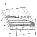
- Fig. 1 is a simplified perspective view shown a section of a wall, this wall partially is cut open to clarify the internal structure.
- the room temperature system comprises a facing 1, the serves as a temperature control element for the room.
- the facing shell 1 is built in front of a building wall 2 and is more suitable Way attached to this.
- the front cover 1 is in a defined distance from the building wall 2, for example approx. 10 cm, which means that it is sealed off from the room Cavity arises.
- the room temperature system also includes one essentially parallel to the wall of the building Partition 3, which the cavity in a room side Flow channel 5 and a flow channel on the building wall side 6 divided.
- the partition 3 extends essentially over the total height of the facing wall.
- a heat exchanger 10 is provided, which itself horizontally along the entire section to be heated Front wall extends.
- the heat exchanger 10 is a convector, which is a metallic pipe Has a large number of metallic fins, too the pipes and fins through a permanent, good thermally conductive, in particular metallic, connection in thermal contact stand.
- the room temperature control system also or exclusively to cool the room, a different one may have to be used Convector and a modified arrangement of the convector can be chosen in the cavity.
- the room temperature control system shown also points a post 15 on both the guide and attachment the partition 3 and the assembly of the actual Attachment shell 1 is used.
- the partition 3 is laterally sealed on the post 15, so that an exact Separation between the flow channel 5 on the room side and the flow channel 6 on the building wall side is ensured.
- the Front shell 1 is in a conventional manner on the front side the post 15 attached.
- the way of this attachment is mainly of the chosen material for the Faceplate 1 dependent, for example, plasterboard Attach to post 15 using suitable screws.
- the material of the facing 1 is made according to the desired Purpose selected. Often come for cost reasons Lightweight panels or gypsum plasterboards are used. As The use of natural or Artificial stone material, especially thin marble slabs proven. Such marble slabs are water resistant, have a very appealing and easy-care surface design on and also have particularly preferred thermal properties. The marble slabs have one much lower thermal resistance than, for example Gypsum plasterboard, so that a significantly shortened Heating phase results. Last but not least, the efficiency of the room temperature control system can be further improved.
- the partition 3 can be made in one piece with the desired dimensions be trained. But it is particularly useful the partition 3 and the other elements attached to it, the described below to produce in standard dimensions and at least in a first component 16, which on its upper end comprises the upper reversing space 8, and a second component 17, which at its lower end includes lower reversal space 7, to divide and only when assembling the room temperature system in the manner shown. During assembly, the length of one or adjust both components in a simple manner so that always the desired height is filled in the facing wall.
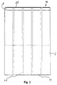
- FIG. 2 shows a view from the front of the first component 16.
- this first component 16 is shown in a side view.
- the partition wall 3 forms the main part of the first component 16.
- the distance between the individual dividers 20 is preferably about 10 cm, the distance dimension to be selected being dependent both on the room height to be heated and on the other fluidic properties of the room temperature control system.
- the dividers 20 on the room side have a height which is adapted to the selected distance between the partition 3 and the facing shell 1 to be applied, so that the end faces of the dividers 20 on the room side lie closely against the back surface of the facing shell, so that the sub-channels 19 formed are separated from one another in terms of flow are.
- a suitable height for the dividers 20 is 3 to 4 cm.
- the upper reversing space 8 At the upper end of the first component 16 is the upper reversing space 8, which creates a connection between the flow channel 5 on the room side and the flow channel 6 on the building wall side.
- the dividers 20 on the room side extend slightly beyond the dividing wall 3 and open uninterruptedly in dividers 21 which run in the region of the upper reversing space 8.
- the dividers 21 in turn open without interruption in dividers 22 on the building wall side, which are fastened to the rear of the dividing wall 3.
- the partition walls 22 on the building wall side extend approximately 30 to 50 cm vertically on the back of the partition wall 3 and run parallel to the partition walls 20 on the room side.
- the partition walls 22 on the building wall side preferably have a height of 1 to 3 cm.
- Across the entire width of the partition wall 3, the partition walls 22 on the building wall side and also the partition walls 21 running in the area of the upper reversal space are covered by a cover plate 25, so that the partial channels 19 in the upper reversing space and in the region of the flow channel 6 on the building wall side delimited by the cover plate 25 also run separately. This measure ensures that no undesired air flows occur between the individual subchannels in the flow channel on the room side, in the reversing space and in the region of the flow channel on the building wall side directly adjacent to these.
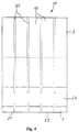
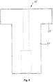
- FIG. 4 shows a front view of the second component 17.
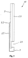
- Fig. 5 is a side view of this second component shown.
- the second component 17 also has Main part of the partition 3, on the front of the room side Separators 20 are arranged.
- the dividers on the room side 20 extend vertically substantially over the total extent of the partition 3.
- At the bottom is the lower reversal chamber 7, again in such a way that the room-side dividers 20 slightly over the partition 3 protrude and in dividers in the area of the reversal area which in turn lead into the back of the partition 3 vertical partition walls 22 without Ignore interruption.
- the dividers on the building wall side 22 also run for a distance of 30 to 50 cm parallel to the dividers 20 on the room side second component 17 has in the area of the lower reversal space 7 and in sections on the back of the partition 3 the cover plate 25 in the manner described above is arranged and fulfills the stated functions.
- the second component 17 differs from the first Component 16 in particular by interrupting the room side Separators 20 slightly above the lower one Reversal space 7.
- third component can be used, which consists only of the partition and attached dividers on the room side consists.
- This third component serves as a connector between the first and the second component and is in its dimensions adapted to this. This way with three components in their dimensions almost all applications for the room temperature control system build up, only a length adjustment of the individual components is required, which is easy to spot can be done.
- the heat exchanger better in the upper part of the Front wall should be positioned, this can by simply exchanging the first and second component and adapted assembly of the posts.
- All components preferably consist of a thermal insulation material.
- Cardboard is particularly suitable for building the preconfigured Construction elements, because it has both good thermal insulation properties achievable as well as a simple adjustment of the Dimensions can be carried out immediately during assembly.
- the Partition 3 can in this case consist of several layers of usual Cardboard plates exist, while the dividers and the cover plate only from a layer of the same type Cardboard are made.
- the connection between the individual Sharing can be done, for example, by gluing.
- the components or individual sections can also be omitted other suitable thermal insulation materials.
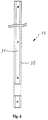
- the post 15 is a front view shown.
- Fig. 7 shows the post in side view and in Fig. 8 is a view of a short side surface of the Post shown.
- the post 15 consists essentially from a strip-shaped support part 30, which in the Assembly of the facing wall attached to the building wall becomes.
- the post 15 has a mounting part 31, which has a rectangular cross section and is in the essentially over the entire length of the support part 30 extends.
- the mounting part 31 is in the lower region interrupted or recessed so that the heat exchanger on this place can be done.
- the support part 30 has a thickness that is the distance between the partition 3 and the building wall 2 determined.
- the partition 3 comes up the area of the support part not occupied by the assembly part to lie so that left and right of the mounting part 31st in each case a partition plate 3 placed on the support part 30 can be.
- the mounting part 31 forms the side Stop for the partition plate 3, i.e. for the first, second and optionally third component of the room temperature control system.
- the end face of the mounting part 31 leading to the room facing, serves as a mounting surface for the Front shell 1.
- the post 15 can be monolithic be or assembled individual parts in the form of the support part and own assembly part.
- Wood is particularly suitable as a material for the post, because it has good thermal insulation properties and is simple Machining and length adjustment is possible. In this case it is useful if the mounting part 31 on the entire surface glued to the support part 30 and optionally additionally is screwed to make changes by warping or To prevent twisting.
- the posts are used when assembling the Room temperature control system in the width of the first and second components 16, 17 predetermined distances on the Building wall 2 installed. If due to the spatial conditions Deviations from this specified distance measure may be necessary, the first, second and, if necessary third components in a simple manner to the required Width can be adjusted.
- the room temperature control system is preferably on external walls of the room to be heated. Of course you can too Interior walls or sloping ceilings facing the interior the room temperature control system. The dimensions of the individual components can be sent to the respective Operating conditions can be easily adapted.
Landscapes
- Engineering & Computer Science (AREA)
- Physics & Mathematics (AREA)
- Thermal Sciences (AREA)
- Chemical & Material Sciences (AREA)
- Combustion & Propulsion (AREA)
- Mechanical Engineering (AREA)
- General Engineering & Computer Science (AREA)
- Building Environments (AREA)
Abstract
Description
- Fig. 1
- eine vereinfachte perspektivische Ansicht eines Abschnitts eines Raumtemperierungssystems, welches in eine Vorsatzschalenwand eingebaut ist;
- Fig. 2
- eine Vorderansicht eines ersten Bauelements des Raumtemperierungssystems mit einem oberen Umkehrraum;
- Fig. 3
- eine Seitenansicht des ersten Bauelements aus Fig. 2;
- Fig. 4
- eine Vorderansicht eines zweiten Bauelements des Raumtemperierungssystems mit einem unteren Umkehrraum;
- Fig. 5
- eine Seitenansicht des Bauelements aus Fig. 4;
- Fig. 6
- eine Vorderansicht eines Pfostens für eine Vorsatzschalenwand mit dem Raumtemperierungssystem;
- Fig. 7
- eine Seitenansicht des Pfostens aus Fig. 6;
- Fig. 8
- eine Ansicht von unten auf den Pfosten aus Fig. 6.
Am oberen Ende des ersten Bauelements 16 befindet sich der obere Umkehrraum 8, der eine Verbindung zwischen dem raumseitigen Strömungskanal 5 und dem bauwerkswandseitigen Strömungskanal 6 herstellt. Dazu verlaufen die raumseitigen Trennstege 20 über die Trennwand 3 geringfügig hinaus und münden unterbrechungsfrei in Trennstege 21, die im Bereich des oberen Umkehrraums 8 verlaufen. Die Trennstege 21 münden ihrerseits unterbrechungsfrei in bauwerkswandseitige Trennstege 22, die auf der Rückseite der Trennwand 3 befestigt sind. Die bauwerkswandseitigen Trennstege 22 erstrecken sich etwa 30 bis 50 cm vertikal auf der Rückseite der Trennwand 3 und verlaufen parallel zu den raumseitigen Trennstegen 20. Die bauwerkswandseitigen Trennstege 22 besitzen vorzugsweise eine Höhe von 1 bis 3 cm. Über die gesamte Breite der Trennwand 3 sind die bauwerkswandseitigen Trennstege 22 und auch die im Bereich des oberen Umkehrraums verlaufenden Trennstege 21 von einer Abdeckplatte 25 überdeckt, so daß die Teilkanäle 19 im oberen Umkehrraum und in dem durch die Abdeckplatte 25 begrenzten Bereich des bauwerkswandseitigen Strömungskanals 6 ebenfalls voneinander getrennt verlaufen. Durch diese Maßnahme ist sichergestellt, daß zwischen den einzelnen Teilkanälen im raumseitigen Strömungskanal, im Umkehrraum und in dem unmittelbar an diesen angrenzenden Bereich des bauwerkswandseitigen Strömungskanals keine ungewollten Luftströmungen entstehen.
Claims (12)
- Raumtemperierungssystem, bei dem Wände oder Wandbereiche des Raums als Temperierungselemente ausgebildet sind, die Wärmestrahlung emittieren oder absorbieren, wobei die Temperierungselemente als Vorsatzschale (1) vor der eigentlichen Bauwerkswand (2) aufgebaut und an dieser befestigt sind, unter Ausbildung eines zum Raum hin dichten Temperierungshohlraums zwischen Vorsatzschale und Bauwerkswand, der seinerseits durch eine im wesentlichen parallel zur Bauwerkswand verlaufende Trennwand (3) in einen raumseitigen Strömungskanal (5) und einen bauwerkswandseitigen Strömungskanal (6), die beide nur über obere und untere Umkehrräume (7, 8) miteinander strömungstechnisch verbunden sind, unterteilt ist und in welchem ein ein Wärmetransportmedium führender Wärmetauscher (10) angeordnet ist, wobei innerhalb des raumseitigen Strömungskanals (5) mehrere vertikal verlaufende raumseitige Trennstege (20) angeordnet sind, dadurch gekennzeichnet, daß sich die raumseitigen Trennstege zwischen Trennwand (3) und Vorsatzschale (1) vom unteren bis zum oberen Umkehrraum erstrecken, parallel zueinander in einem Abstand von 5 bis 20 cm verlaufen, nur vom Wärmetauscher (10) unterbrochen sind und strömungstechnisch voneinander getrennte Teilkanäle (19) ausbilden, daß die raumseitigen Trennstege (20) in im Bereich der Umkehrräume (7, 8) verlaufende Trennstege (21) übergehen, die ihrerseits in bauwerkswandseitige Trennstege (22) übergehen, welche innerhalb des bauwerkswandseitigen Strömungskanals (6) ausgehend vom oberen bzw. unteren Umkehrraum wenigstens ca. 30 cm vertikal weiter verlaufen, wodurch die Teilkanäle (19) auch in den Umkehrräumen (7, 8) und im bauwerkswandseitigen Strömungskanal (6) wenigstens in den unmittelbar an die Umkehrräume anschließenden Abschnitten strömungstechnisch voneinander getrennt sind, und daß die Trennstege (21, 22) im Bereich der Umkehrräume (7, 8) und des bauwerkswandseitigen Strömungskanals (6) zur Gewährleistung einer exakten strömungstechnischen Trennung der Teilkanäle von einer alle Teilkanäle übergreifenden Abdeckplatte (25) überdeckt sind.
- Raumtemperierungssystem nach Anspruch 1, dadurch gekennzeichnet, daß der Wärmetauscher (10) geringfügig oberhalb des unteren Umkehrraums (7) horizontal im raumseitigen Strömungskanal (5) angeordnet ist.
- Raumtemperierungssystem nach Anspruch 1 oder 2, dadurch gekennzeichnet, daß die Trennwand (3) aus einem Wärmedämmaterial besteht.
- Raumtemperierungssystem nach einem der Ansprüche 1 bis 3, dadurch gekennzeichnet, daß die Trennwand (3), die Trennstege (20, 21, 22) und die Abdeckplatte (25) aus Pappe bestehen.
- Raumtemperierungssystem nach einem der Ansprüche 1 bis 4, dadurch gekennzeichnet, daß der horizontale Abstand zwischen den Trennstegen (20, 21, 22) 10 bis 12 cm, der Spalt zwischen der Bauwerkswand (2) und der Trennwand (3) 1 bis 3 cm und der Spalt zwischen der Vorsatzschale (1) und der Trennwand (3) 2 bis 5 cm beträgt.
- Raumtemperierungssystem nach einem der Ansprüche 1 bis 5, dadurch gekennzeichnet, daß vorkonfigurierte Bauelemente (16, 17) eingesetzt sind, die aus der Trennwand (3) , den Trennstegen (20, 21 22) und der Abdeckplatte (25) bestehen, die fest miteinander verbunden sind.
- Raumtemperierungssystem nach einem der Ansprüche 1 bis 6, dadurch gekennzeichnet, daß es in eine Vorsatzschalenwand integriert ist.
- Raumtemperierungssystem nach Anspruch 7, dadurch gekennzeichnet, daß die Trennwand (3) jeweils zwischen zwei Pfosten (15) über die gesamte Höhe der Vorsatzschalenwand angeordnet ist, wobei die Pfosten (15) ein leistenförmiges an der Bauwerkswand anliegendes Auflageteil (30) besitzen, dessen Stärke den Abstand zwischen Trennwand (3) und Bauwerkswand (2) bestimmt, daß im wesentlichen über die gesamte Länge des Auflageteils (30) ein quaderförmiges Montageteil (31) symmetrisch angebracht ist, dessen Breite geringer als die des Auflageteils ist und dessen Stärke den Abstand zwischen Trennwand (3) und Vorsatzschale (1) bestimmt, so daß die Trennwand auf der verbleibenden Fläche des Auflageteils (30) zu liegen kommt und seitlich vom Montageteil (31) geführt wird, und daß die Vorsatzschale (1) an der Stirnfläche des Montageteils (31) befestigbar ist, wobei das Montageteil im Bereich des Wärmetauschers (10) ausgespart ist.
- Raumtemperierungssystem nach einem der Ansprüche 1 bis 8, dadurch gekennzeichnet, daß die Vorsatzschale (1) aus Leichtbauplatten, insbesondere Gipskartonplatten besteht.
- Raumtemperierungssystem nach einem der Ansprüche 1 bis 8, dadurch gekennzeichnet, daß die Vorsatzschale (1) aus Natur- oder Kunststeinplatten besteht.
- Raumtemperierungssystem nach einem der Ansprüche 1 bis 10, dadurch gekennzeichnet, daß es als Heizung dient, daß der Wärmetauscher (10) von erhitztem Wasser durchflossen wird, daß im raumseitigen Strömungskanal (5) die durch den Wärmetauscher erwärmte Luft geleitet wird, welche beim Aufsteigen die Vorsatzschale (1) erwärmt und dadurch selbst abkühlt, und daß im bauwerkswandseitigen Strömungskanal (6) die abgekühlte Luft nach unten geleitet wird.
- Raumtemperierungssystem nach einem der Ansprüche 1 bis 10, dadurch gekennzeichnet, daß der Wärmetauscher (10) von einem gekühlten Medium durchflossen wird, so daß das Raumtemperierungssystem als Kühlanlage dient.
Applications Claiming Priority (2)
| Application Number | Priority Date | Filing Date | Title |
|---|---|---|---|
| DE19712744A DE19712744C1 (de) | 1997-03-26 | 1997-03-26 | Raumtemperierungssystem |
| DE19712744 | 1997-03-26 |
Publications (2)
| Publication Number | Publication Date |
|---|---|
| EP0867664A2 true EP0867664A2 (de) | 1998-09-30 |
| EP0867664A3 EP0867664A3 (de) | 2000-05-10 |
Family
ID=7824717
Family Applications (1)
| Application Number | Title | Priority Date | Filing Date |
|---|---|---|---|
| EP98105251A Withdrawn EP0867664A3 (de) | 1997-03-26 | 1998-03-23 | Raumtemperierungssystem |
Country Status (2)
| Country | Link |
|---|---|
| EP (1) | EP0867664A3 (de) |
| DE (1) | DE19712744C1 (de) |
Families Citing this family (2)
| Publication number | Priority date | Publication date | Assignee | Title |
|---|---|---|---|---|
| DE29922798U1 (de) | 1999-12-24 | 2000-03-09 | Barath, Gisela, 41472 Neuss | Vorrichtung zur Temperierung von Räumen |
| DE10254240A1 (de) * | 2002-11-20 | 2004-06-09 | Weiss Umwelttechnik Gmbh | Kammer sowie Verfahren zur Messung von Verdunstungs- bzw. Verdampfungsemission |
Citations (4)
| Publication number | Priority date | Publication date | Assignee | Title |
|---|---|---|---|---|
| CH254181A (fr) | 1945-05-19 | 1948-04-30 | Finet Andre Leon Emile | Dispositif pour conférer à un local une température donnée. |
| EP0223241A2 (de) | 1985-11-18 | 1987-05-27 | Hans-Joachim Eckert | Vorrichtung zum Temperieren von Boden- und Wandflächen |
| DE9406473U1 (de) | 1993-04-22 | 1994-06-16 | Berger, Harro, Mag., Wien | Wandheizung |
| DE19514296A1 (de) | 1995-04-24 | 1996-10-31 | Schaefer Werke Gmbh | Heizkörper |
-
1997
- 1997-03-26 DE DE19712744A patent/DE19712744C1/de not_active Expired - Fee Related
-
1998
- 1998-03-23 EP EP98105251A patent/EP0867664A3/de not_active Withdrawn
Patent Citations (4)
| Publication number | Priority date | Publication date | Assignee | Title |
|---|---|---|---|---|
| CH254181A (fr) | 1945-05-19 | 1948-04-30 | Finet Andre Leon Emile | Dispositif pour conférer à un local une température donnée. |
| EP0223241A2 (de) | 1985-11-18 | 1987-05-27 | Hans-Joachim Eckert | Vorrichtung zum Temperieren von Boden- und Wandflächen |
| DE9406473U1 (de) | 1993-04-22 | 1994-06-16 | Berger, Harro, Mag., Wien | Wandheizung |
| DE19514296A1 (de) | 1995-04-24 | 1996-10-31 | Schaefer Werke Gmbh | Heizkörper |
Also Published As
| Publication number | Publication date |
|---|---|
| EP0867664A3 (de) | 2000-05-10 |
| DE19712744C1 (de) | 1998-11-12 |
Similar Documents
| Publication | Publication Date | Title |
|---|---|---|
| DE8390053U1 (de) | Wärmeaustauscher-Vorrichtung | |
| AT505298B1 (de) | Plattenförmiges verkleidungselement für eine mauer und mauerverkleidung | |
| DE3932972A1 (de) | Kuehl- oder heizelement | |
| DE68914246T2 (de) | Vorgefertigte Elemente für Klimatisation durch Strahlung oder Strahlung/Ventilation und eine diese Elemente enthaltende Klimaanlage. | |
| EP0927323B1 (de) | Kühldecke, elemente für kühldecke und kühlrohrmatte zur anwendung bei einer kühldecke | |
| EP0670985B1 (de) | Wandelement mit integrierter heizung | |
| EP1344987A2 (de) | Flächenheiz- und Kühlelement | |
| DE19636944A1 (de) | Kühldecke, Elemente für Kühldecke und Kühlrohrmatte zur Anwendung bei einer Kühldecke | |
| EP2045536A2 (de) | Kühl-, Heiz- und Akustikplattenelement | |
| DE19712744C1 (de) | Raumtemperierungssystem | |
| WO2013087225A1 (de) | Gebäude mit einem in eine betondecke des gebäudes integrierten raumkonditionierungssystem zum kühlen, heizen und zur belüftung | |
| DE202007017185U1 (de) | Wärmeverbundsystem sowie ein Flächenheizungs/-kühlungs-Baukastensystem mit einem derartigen Wärmeverbundsystem | |
| DE19908992C2 (de) | Vorrichtung zum Temperieren von an eine Fassade angrenzenden Innenräumen | |
| EP0150242A1 (de) | Fertigteil zum Aufbau eines über seine Wände klimatisierten Gebäudes | |
| DE202022106997U1 (de) | Wärmeübertragungsvorrichtung zum Kühlen bzw. Heizen von Räumen | |
| DE3147632C2 (de) | Anordnung zur Absorption von Umweltenergie an einer Gebäudeaußenwand | |
| DE2364013A1 (de) | Flaechenheizkoerper | |
| WO2007042331A1 (de) | Wärmetauscherplatte | |
| DE19738172C1 (de) | Einrichtung zum Temperieren von Gebäuden | |
| DE3507594A1 (de) | Aussenwandkonstruktion an einem bauwerk | |
| WO1988001664A1 (fr) | Element de construction polyvalent | |
| EP0374527A2 (de) | Luftverteilsystem | |
| DE69525672T2 (de) | Gebäudekonstruktionen und Verfahren zur Temperatursteuerung des Innenraums solcher Gebäude | |
| DE29503973U1 (de) | Raumklimasystem mit Speicherschicht | |
| DE3118052A1 (de) | Lueftungseinrichtung |
Legal Events
| Date | Code | Title | Description |
|---|---|---|---|
| PUAI | Public reference made under article 153(3) epc to a published international application that has entered the european phase |
Free format text: ORIGINAL CODE: 0009012 |
|
| AK | Designated contracting states |
Kind code of ref document: A2 Designated state(s): AT BE CH DK FR LI NL SE |
|
| AX | Request for extension of the european patent |
Free format text: AL;LT;LV;MK;RO;SI |
|
| PUAL | Search report despatched |
Free format text: ORIGINAL CODE: 0009013 |
|
| AK | Designated contracting states |
Kind code of ref document: A3 Designated state(s): AT BE CH DE DK ES FI FR GB GR IE IT LI LU MC NL PT SE |
|
| AX | Request for extension of the european patent |
Free format text: AL;LT;LV;MK;RO;SI |
|
| 17P | Request for examination filed |
Effective date: 20001103 |
|
| AKX | Designation fees paid |
Free format text: AT BE CH DK FR LI NL SE |
|
| REG | Reference to a national code |
Ref country code: DE Ref legal event code: 8566 |
|
| GRAH | Despatch of communication of intention to grant a patent |
Free format text: ORIGINAL CODE: EPIDOS IGRA |
|
| STAA | Information on the status of an ep patent application or granted ep patent |
Free format text: STATUS: THE APPLICATION IS DEEMED TO BE WITHDRAWN |
|
| 18D | Application deemed to be withdrawn |
Effective date: 20030507 |