EP0867699A2 - Verfahren und Vorrichtung für Temperaturmessung mit Nutzung der Infrarottechnik - Google Patents
Verfahren und Vorrichtung für Temperaturmessung mit Nutzung der Infrarottechnik Download PDFInfo
- Publication number
- EP0867699A2 EP0867699A2 EP98201500A EP98201500A EP0867699A2 EP 0867699 A2 EP0867699 A2 EP 0867699A2 EP 98201500 A EP98201500 A EP 98201500A EP 98201500 A EP98201500 A EP 98201500A EP 0867699 A2 EP0867699 A2 EP 0867699A2
- Authority
- EP
- European Patent Office
- Prior art keywords
- laser
- radiometer
- laser beam
- energy zone
- infrared
- Prior art date
- Legal status (The legal status is an assumption and is not a legal conclusion. Google has not performed a legal analysis and makes no representation as to the accuracy of the status listed.)
- Granted
Links
Images


Classifications
-
- G—PHYSICS
- G01—MEASURING; TESTING
- G01J—MEASUREMENT OF INTENSITY, VELOCITY, SPECTRAL CONTENT, POLARISATION, PHASE OR PULSE CHARACTERISTICS OF INFRARED, VISIBLE OR ULTRAVIOLET LIGHT; COLORIMETRY; RADIATION PYROMETRY
- G01J5/00—Radiation pyrometry, e.g. infrared or optical thermometry
- G01J5/02—Constructional details
- G01J5/08—Optical arrangements
- G01J5/0859—Sighting arrangements, e.g. cameras
-
- G—PHYSICS
- G01—MEASURING; TESTING
- G01J—MEASUREMENT OF INTENSITY, VELOCITY, SPECTRAL CONTENT, POLARISATION, PHASE OR PULSE CHARACTERISTICS OF INFRARED, VISIBLE OR ULTRAVIOLET LIGHT; COLORIMETRY; RADIATION PYROMETRY
- G01J5/00—Radiation pyrometry, e.g. infrared or optical thermometry
- G01J5/02—Constructional details
- G01J5/0265—Handheld, portable
-
- G—PHYSICS
- G01—MEASURING; TESTING
- G01J—MEASUREMENT OF INTENSITY, VELOCITY, SPECTRAL CONTENT, POLARISATION, PHASE OR PULSE CHARACTERISTICS OF INFRARED, VISIBLE OR ULTRAVIOLET LIGHT; COLORIMETRY; RADIATION PYROMETRY
- G01J5/00—Radiation pyrometry, e.g. infrared or optical thermometry
- G01J5/02—Constructional details
- G01J5/0275—Control or determination of height or distance or angle information for sensors or receivers
-
- G—PHYSICS
- G01—MEASURING; TESTING
- G01J—MEASUREMENT OF INTENSITY, VELOCITY, SPECTRAL CONTENT, POLARISATION, PHASE OR PULSE CHARACTERISTICS OF INFRARED, VISIBLE OR ULTRAVIOLET LIGHT; COLORIMETRY; RADIATION PYROMETRY
- G01J5/00—Radiation pyrometry, e.g. infrared or optical thermometry
- G01J5/02—Constructional details
- G01J5/07—Arrangements for adjusting the solid angle of collected radiation, e.g. adjusting or orienting field of view, tracking position or encoding angular position
-
- G—PHYSICS
- G01—MEASURING; TESTING
- G01J—MEASUREMENT OF INTENSITY, VELOCITY, SPECTRAL CONTENT, POLARISATION, PHASE OR PULSE CHARACTERISTICS OF INFRARED, VISIBLE OR ULTRAVIOLET LIGHT; COLORIMETRY; RADIATION PYROMETRY
- G01J5/00—Radiation pyrometry, e.g. infrared or optical thermometry
- G01J5/02—Constructional details
- G01J5/08—Optical arrangements
- G01J5/0813—Planar mirrors; Parallel phase plates
-
- G—PHYSICS
- G01—MEASURING; TESTING
- G01J—MEASUREMENT OF INTENSITY, VELOCITY, SPECTRAL CONTENT, POLARISATION, PHASE OR PULSE CHARACTERISTICS OF INFRARED, VISIBLE OR ULTRAVIOLET LIGHT; COLORIMETRY; RADIATION PYROMETRY
- G01J5/00—Radiation pyrometry, e.g. infrared or optical thermometry
- G01J5/02—Constructional details
- G01J5/08—Optical arrangements
- G01J5/084—Adjustable or slidable
-
- G—PHYSICS
- G01—MEASURING; TESTING
- G01J—MEASUREMENT OF INTENSITY, VELOCITY, SPECTRAL CONTENT, POLARISATION, PHASE OR PULSE CHARACTERISTICS OF INFRARED, VISIBLE OR ULTRAVIOLET LIGHT; COLORIMETRY; RADIATION PYROMETRY
- G01J5/00—Radiation pyrometry, e.g. infrared or optical thermometry
- G01J5/02—Constructional details
- G01J5/08—Optical arrangements
- G01J5/0896—Optical arrangements using a light source, e.g. for illuminating a surface
-
- G—PHYSICS
- G01—MEASURING; TESTING
- G01J—MEASUREMENT OF INTENSITY, VELOCITY, SPECTRAL CONTENT, POLARISATION, PHASE OR PULSE CHARACTERISTICS OF INFRARED, VISIBLE OR ULTRAVIOLET LIGHT; COLORIMETRY; RADIATION PYROMETRY
- G01J5/00—Radiation pyrometry, e.g. infrared or optical thermometry
- G01J5/48—Thermography; Techniques using wholly visual means
-
- Y—GENERAL TAGGING OF NEW TECHNOLOGICAL DEVELOPMENTS; GENERAL TAGGING OF CROSS-SECTIONAL TECHNOLOGIES SPANNING OVER SEVERAL SECTIONS OF THE IPC; TECHNICAL SUBJECTS COVERED BY FORMER USPC CROSS-REFERENCE ART COLLECTIONS [XRACs] AND DIGESTS
- Y10—TECHNICAL SUBJECTS COVERED BY FORMER USPC
- Y10S—TECHNICAL SUBJECTS COVERED BY FORMER USPC CROSS-REFERENCE ART COLLECTIONS [XRACs] AND DIGESTS
- Y10S33/00—Geometrical instruments
- Y10S33/21—Geometrical instruments with laser
Definitions
- the present invention relates generally to a method and apparatus for more accurately measuring the temperature of a surface using infrared measurement techniques and, more particularly, to such a method and apparatus which utilizes a circumscribing laser sighting beam or beams for more clearly defining the periphery of the energy zone from which the temperature is measured.
- this is accomplished by rotating the laser beam about the periphery of the energy zone; by the use of two or more stationery laser beams which are focused on the periphery of the energy zone; or by the use of a controlled single laser beam directed towards two or more predetermined locations on the periphery of the energy zone.
- Remote infrared temperature measuring devices have been used for many years to measure the temperature of a surface from a remote location. Their principle of operation is well known. All surfaces at a temperature above absolute zero emit heat in the form of radiated energy. This radiated energy is created by molecular motion which produces electromagnetic waves. Thus, some of the energy in the material is radiated in straight lines away from the surface of the material. Many infrared radiometers use optical reflection and/or refraction principles to capture the radiated energy from a given surface. The infrared radiation is focused upon a detector, analyzed and, using well known techniques, the surface energy is collected, processed and the temperature is calculated and displayed on an appropriate display.
- the instrument When using such radiometers to measure surface temperature, the instrument is aimed at a target or "spot" within the energy zone on the surface on which the measurement is to be taken.
- the radiometer receives the emitted radiation through the optical system and is focused upon an infrared sensitive detector which generates a signal which is internally processed and converted into a temperature reading which is displayed.
- the precise location of the energy zone on the surface as well as its size are extremely important to insure accuracy and reliability of the resultant measurement. It will be readily appreciated that the field of view of the optical systems of such radiometers is such that the diameter of the energy zone increases directly with the distance to the target.
- the typical energy zone of such radiometers is defined as where 90% of the energy focused upon the detector is found.
- there have been no means of accurately determining the size of the actual energy zone unless it is approximated by the use of a "distance to target table" or by actual physical measurement.
- the minimum measurement spot occurs at the specified focal distance.
- the minimum spot (resolution) the instrument can achieve is 60 divided by 120, or .5" at a distance of 60" from the instrument. This is significant when the size of the object is close to the minimum spot the instrument can measure.
- thermometers use of focal distance of between 20" and 60" (50 and 150cm); special close-focus instruments use a .5" to 12" focal distance. See page 254 and 255, Volume 28, The Omega Engineering Handbook , Vol. 28.
- laser beam sighting devices have been used to target the precise center of the energy zone. See, for example, Pages C1-10 through C1-12 of The Omega Temperature Handbook , Vol. 27.
- Various sighting devices such as scopes with cross hairs have also been used to more accurately identify the center of the energy zone to be measured. See, for example, Pages C1-10 through C1-21 of The Omega Temperature Handbook , Vol. 27.
- One method used to determine the distance to the target is to employ an infrared distance detector or a Doppler effect distance detector or a split image detector similar to that used in photography.
- the exact size of the energy zone must still be known if one is to have any degree of certainty as to the actual area of the surface being measured. This is particularly true if the energy zone is too small or the surface on which the energy zone encompasses is irregular in shape. In the case where the surface does not fill the entire energy zone area, the readings will be low and, thus, in error.
- the readings will also be in error since part of the object would be missing from the actual energy zone being measured.
- the use of a single laser beam to the apparent center of the energy zone does not insure complete accuracy since the user of the radiometer does not know specifically the boundaries of the energy zone being measured.
- the present invention in brief summary, comprises method and apparatus for visibly outlining the energy zone to be measured by a radiometer.
- the method comprises the steps of providing a laser sighting device on the radiometer adapted to emit at least one laser beam against a surface whose temperature is to be measured and controlling said laser beam about the energy zone to visibly outline said energy zone.
- the beam would be controlled in such a fashion where it is directed to predetermined points of the target zone. This can be done mechanically or electrically.
- Another embodiment of this invention employs a plurality of laser beams to describe the outline of the energy zone either by splitting the laser beam into a number of points through the use of optical fibers or beam splitters or the use of a plurality of lasers.
- One embodiment of the apparatus comprises a laser sighting device adapted to emit at least one laser beam against the surface and means to rotate said laser beam about the energy zone to visibly outline said energy zone. This rotation can be by steps or continuous motion.
- Another embodiment consists of two or more stationary beams directed to define the energy zone.
- the two or more laser beams could be derived from a dedicated laser to each beam or by means of beam splitters. This can be accomplished by mirrors, optics and fiber optics.
- Another embodiment consists of a laser beam splitting device that emits one laser beam which is split into a plurality of beams that outline the energy zone.
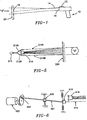
- FIG. 1 illustrates the operation of traditional, prior art, hand held radiometers.
- a radiometer referred to generally by reference numeral 10
- This spot 18 is located in the center of the energy zone "E" which is to be measured by the radiometer 10.
- This radiometer 18 includes a detector 16 which is connected to conventional internal circuitry and display means (not shown) for conversion, calculation and display of the temperature of the surface 20 calculated indirectly from the energy radiated from the surface within the energy zone E.
- Such energy is radiated in straight lines in all directions away from the surface 20 and captured with the detector 16 on the radiometer 10.
- the radiometer is thus able to capture and measure the infrared energy in the energy zone E and determine the surface temperature thereof.
- the actual size and shape of the energy zone E is determined by the optics of the radiometer and the distance between the radiometer and the target.
- Bach radiometer has a defined angle of vision or "field of view" which is typically identified in the instrument's specification sheet.
- the size of the energy zone E is predetermined when the field of view is known in conjunction with the distance to the target. Obviously, the further the radiometer is held from the target (i.e., the greater the distance), the larger the energy zone E.
- distance to spot size ratio This can be expressed in a "distance to spot size ratio.” For example, with a “distance to spot size ratio of 40:1 the periphery of the energy zone would have a 1" diameter at a distance of 40" or, at a distance of 20" the diameter of the energy zone would be 1/2".
- the manufacturer of the pyrometer usually provides field of view diagrams for determining the energy zone at specific distances.
- such laser aiming devices are merely able to identify the center of the energy zone being measured and not the outer periphery of the actual energy zone from which the measurement is being taken.
- the farther away from the surface the radiometer 10 is positioned the larger the energy zone E.
- the actual energy zone E may, conceivably, include irregular shaped portions of the surface 20 or even extend beyond the edges of the surface.
- the resultant measured temperature would be inaccurate.
- the user of the radiometer 10 would have no knowledge of such fact or that the resultant readings could be inaccurate.
- the present invention provides a means for visibly defining the energy zone E so that the user of the radiometer 10 can observe the actual energy zone being measured to determine where it falls relative to the surface being measured.
- a fine laser line or lines is projected against the surface being measured and such line or lines is positioned so as to encompass the periphery of the energy zone E. If a rotating laser beam is employed, positioning can be effected, alternatively, by moving either the laser itself or the laser beam emitted from the laser.
- the perimeter of the energy zone E could be identified on the object by the movement of the laser beam in a path about the circumference of the energy zone E, the user would be able to quickly and accurately determine if the energy zone from which the measurement was being taken was fully on the surface to be measured and whether its surface was of a type which would provide an otherwise accurate measurement.
- the periphery of the energy zone E is identified as a function of the stated "field of view” of the particular radiometer as identified in its specifications and the distance between the radiometer and the target. Identification of the size and shape of the energy zone is easily done using conventional mathematical formulas. Once identified, the laser beam is then projected about the periphery of the energy zone E in accordance with the methods and apparatus hereinafter described.
- One simple "aiming" approach is to project the laser beam at the same angle as the field of view of the radiometer emulating from the same axis or, alternatively, by mechanically adjusting the laser beam angle in accordance with the "distance to spot size ratio" calculations. In either event, the periphery of the energy zone E would be identified by the laser beam.
- Fig. 2 illustrates a first embodiment of the present invention in which the laser aiming device 12 emits a laser beam 14 which is aimed at a mirrored surface 30 which is positioned in front of the laser beam 14.
- the mirror 30 is rotated using motive means 32 so as to rotate the beam in a circular fashion to define the energy zone E on the surface being measured.
- the mirror 30 can be rotated by vibratory means or by the application of a magnetic field (not shown). Rotation of the mirror 30 should be at a refraction angle which corresponds to the 90% energy zone E thereby permitting the laser beam 14 to rotate about the periphery of the energy zone E thereby making it visible to the user of the radiometer 10.
- a prism can be used in place of the mirror 30 with predetermined angles to cause the prism to function as the reflecting mirror surface and, thereby, direct the laser beam about the perimeter of the energy zone.
- Figs. 2A and 2B illustrate the manner in which the laser beams can be used to outline the energy zone E on the surface to be measured. It is important that rotation of the beam 14 be carefully controlled so that rotation is at such a speed which can be visually followed. This will permit full beam intensity.
- the laser beam is rotated about the energy zone E through a series of steps with the laser beam being permitted to remain in each step for at least one hundredth of a second before moving to its next position. This is accomplished by creating a plurality of steps E-1, E-2 etc., around the energy zone E.
- the laser beam 114 would stop at each step for the predetermined period of time to permit the beam to be visually observed before moving to the next step.
- Fig. 3 illustrates another embodiment of the present invention in which the laser 112 itself is rotated or displaced so as to scribe a circle which defines the energy zone E by mechanically pivoting the laser 112 about pivot point 120 using motive means 132.
- the laser 112 can be rotated by vibratory means (not shown) or by the application of a magnetic field (not shown). Rotation of the laser 112 should, however, be at a refraction angle which corresponds to the 90% energy zone E thereby permitting the laser beam 114 to rotate about the periphery of the energy zone E to make it visible to the user of the radiometer 10.
- the laser 212 is rotated about a pivot point 220 by the application of a magnetic field 225 so as cause the emission of the laser beam 214 around the periphery of the 90% energy zone E to make the beam visible to the user of the radiometer 10.
- means are provided for modifying the magnetic field 225 to correspond to the 90% energy zone so as to permit the laser to be rotated accordingly.
- the laser 312 has at least two components 312A and 312B which produce at least two individual laser beams 314A and 314B about the detector 316. These at least two individual beams 314A and 314B are directed to the surface 320 being measured at the perimeter of the energy zone E rather than at its center. Through the use of a number of such laser beams, the energy zone E becomes clearly identified rather than merely the center of the energy zone E. If desired, individual lasers can be used or laser splitting devices can be used to split a single laser beam.
- Fig. 6 illustrates yet another embodiment of the present invention in which the laser 412 is mechanically pivoted in a circular fashion around the detector 416 so as to emit a laser beam 414 in a circular path on the surface (not shown) thereby defining the energy zone E.
- Laser 412 is pivotally mounted on pivot bearing 420 provided on connecting arm 421.
- Arm 421 is mounted on pivot bearing 424 which is rotated by motor 422. In such a manner, the laser beam 414 emitted from the laser 412 rotates about and outlines the energy zone E on the surface from which the temperature is being measured.
- the rotation of the laser beam may also be effected using fiber optics techniques as shown in Fig. 7 in which the laser beam is projected through fiber optics means 501. In such manner, the beam fans out from the laser source and encircles and thereby defines the energy zone E.
- fiber optics By the use of a sufficient number of fiber optics, one can outline the circumference of the target area E with a light ring. This can be accomplished by as few as two fibers 501 positioned 180 degrees apart since the pick up pattern would be circular.
- Fig. 8 illustrates still another means of effecting rotation of the laser beam 614 emitted from laser 612.
- the laser beam 614 is directed against a rotating flat surface mirror 630 where it is reflected against a plated plastic cone mirror 631.
- the reflected beam is then projected to the surface and defines the perimeter of the energy zone E.
- the flat mirror 630 is driven by motor 622.
- the laser beam 614 rotates about the circumference of the energy zone E on the surface being measured.
- the mirrors are positioned at such an angle that the laser projection is at the same angle as the infrared detector pickup angle.
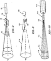
- Figs. 9A-C illustrate alternative square (Fig. 9A), rectangular (Fig. 9B) and triangular (Fig. 9C) configurations for the light patterns which may be accomplished using the means of the present invention.
- Fig. 10 illustrates a method for defining the energy zone where a circular configuration can be accomplished without rotation of the laser beam wherein a plurality of fixed optical fibers positioned to project a number of spots is employed.
- a fixed laser 712 projects a beam 713 which is split into a plurality of beams 714 by a bundle of optical fibers 715 in order to project a pattern 716 onto the surface defining the energy zone E. Additional configurations may also be used, if desired.
Landscapes
- Physics & Mathematics (AREA)
- General Physics & Mathematics (AREA)
- Spectroscopy & Molecular Physics (AREA)
- Radiation Pyrometers (AREA)
Priority Applications (2)
| Application Number | Priority Date | Filing Date | Title |
|---|---|---|---|
| DE9422259U DE9422259U1 (de) | 1993-09-17 | 1994-02-23 | Vorrichtung zum Messen der Temperatur unter Verwendung von Infrarot-Techniken |
| EP04077059A EP1475619A3 (de) | 1993-09-17 | 1994-02-23 | Verfahren und Vorrichtung für Temperaturmessung mit Nutzung der Infrarottechnik |
Applications Claiming Priority (3)
| Application Number | Priority Date | Filing Date | Title |
|---|---|---|---|
| US08121916 US5368392B1 (en) | 1993-09-17 | 1993-09-17 | Method and apparatus for measuring temperature using infrared techniques |
| EP94301275A EP0644408B1 (de) | 1993-09-17 | 1994-02-23 | Verfahren und Vorrichtung zur Temperaturmessung mittels Infrarottechnik |
| US121916 | 1998-07-24 |
Related Parent Applications (1)
| Application Number | Title | Priority Date | Filing Date |
|---|---|---|---|
| EP94301275A Division EP0644408B1 (de) | 1993-09-17 | 1994-02-23 | Verfahren und Vorrichtung zur Temperaturmessung mittels Infrarottechnik |
Related Child Applications (1)
| Application Number | Title | Priority Date | Filing Date |
|---|---|---|---|
| EP04077059A Division EP1475619A3 (de) | 1993-09-17 | 1994-02-23 | Verfahren und Vorrichtung für Temperaturmessung mit Nutzung der Infrarottechnik |
Publications (3)
| Publication Number | Publication Date |
|---|---|
| EP0867699A2 true EP0867699A2 (de) | 1998-09-30 |
| EP0867699A3 EP0867699A3 (de) | 1998-11-04 |
| EP0867699B1 EP0867699B1 (de) | 2008-04-30 |
Family
ID=22399511
Family Applications (3)
| Application Number | Title | Priority Date | Filing Date |
|---|---|---|---|
| EP98201500A Expired - Lifetime EP0867699B1 (de) | 1993-09-17 | 1994-02-23 | Verfahren und Vorrichtung für Temperaturmessung mit Nutzung der Infrarottechnik |
| EP04077059A Withdrawn EP1475619A3 (de) | 1993-09-17 | 1994-02-23 | Verfahren und Vorrichtung für Temperaturmessung mit Nutzung der Infrarottechnik |
| EP94301275A Expired - Lifetime EP0644408B1 (de) | 1993-09-17 | 1994-02-23 | Verfahren und Vorrichtung zur Temperaturmessung mittels Infrarottechnik |
Family Applications After (2)
| Application Number | Title | Priority Date | Filing Date |
|---|---|---|---|
| EP04077059A Withdrawn EP1475619A3 (de) | 1993-09-17 | 1994-02-23 | Verfahren und Vorrichtung für Temperaturmessung mit Nutzung der Infrarottechnik |
| EP94301275A Expired - Lifetime EP0644408B1 (de) | 1993-09-17 | 1994-02-23 | Verfahren und Vorrichtung zur Temperaturmessung mittels Infrarottechnik |
Country Status (4)
| Country | Link |
|---|---|
| US (2) | US5368392B1 (de) |
| EP (3) | EP0867699B1 (de) |
| CA (1) | CA2114806C (de) |
| DE (4) | DE867699T1 (de) |
Cited By (3)
| Publication number | Priority date | Publication date | Assignee | Title |
|---|---|---|---|---|
| DE10036720A1 (de) * | 2000-07-27 | 2002-02-07 | Raytek Gmbh | Vorrichtung und Verfahren zur Infrarot-Temperaturmessung |
| DE10336097B3 (de) * | 2003-08-06 | 2005-03-10 | Testo Ag | Visiereinrichtung für ein Radiometer sowie Verfahren |
| US7025499B2 (en) | 2000-10-24 | 2006-04-11 | Robert Bosch Gmbh | Device for testing a material that changes shape when an electric and/or magnetic field is applied |
Families Citing this family (51)
| Publication number | Priority date | Publication date | Assignee | Title |
|---|---|---|---|---|
| US10361802B1 (en) | 1999-02-01 | 2019-07-23 | Blanding Hovenweep, Llc | Adaptive pattern recognition based control system and method |
| US5823678A (en) * | 1993-09-17 | 1998-10-20 | Omega Engineering, Inc. | Light source aiming system and method for hand-held temperature measuring unit |
| US20030185273A1 (en) * | 1993-09-17 | 2003-10-02 | Hollander Milton Bernard | Laser directed temperature measurement |
| US5823679A (en) * | 1993-09-17 | 1998-10-20 | Omega Engineering, Inc. | Method and apparatus for measuring temperature including aiming light |
| US5727880A (en) * | 1993-09-17 | 1998-03-17 | Omega Engineering, Inc. | Method and apparatus for measuring temperature using infrared techniques |
| US5491546A (en) * | 1994-02-17 | 1996-02-13 | Wascher; Rick R. | Laser assisted telescopic target sighting system and method |
| US5626424A (en) * | 1994-07-21 | 1997-05-06 | Raytek Subsidiary, Inc. | Dual light source aiming mechanism and improved actuation system for hand-held temperature measuring unit |
| US5533268A (en) * | 1994-08-08 | 1996-07-09 | Miles D. Willetts | Laser deflection apparatus for laser compass |
| US6290389B2 (en) * | 1995-08-03 | 2001-09-18 | Raytek Gmbh | Device for temperature measurement |
| DE19528590C3 (de) * | 1995-08-03 | 2003-11-27 | Raytek Gmbh | Vorrichtung zur Temperaturmessung |
| JP3277776B2 (ja) | 1995-11-20 | 2002-04-22 | ミノルタ株式会社 | 放射温度計の照準装置 |
| JPH1020765A (ja) * | 1996-07-04 | 1998-01-23 | Sekinosu Kk | レーザーポインター |
| US5836694A (en) * | 1996-12-10 | 1998-11-17 | Raytek Subsidiary, Inc. | Laser and scope aiming mechanism for a hand-held temperature measuring unit |
| FR2773214B1 (fr) * | 1996-12-11 | 2002-05-31 | Omega Engineering | Procede et dispositif pour la mesure par infrarouge de la temperature d'une surface |
| DE19654276A1 (de) * | 1996-12-24 | 1998-06-25 | Raytek Gmbh | Vorrichtung zur berührungslosen Temperaturmessung |
| CA2254438C (en) * | 1997-11-21 | 2008-04-01 | Omega Engineering, Inc. | Pyrometer-multimeter |
| US6901089B1 (en) * | 1999-07-02 | 2005-05-31 | Milton Bernard Hollander | Laser instrument |
| US6377400B1 (en) * | 1999-07-02 | 2002-04-23 | Milton Bernard Hollander | Laser sighting beam modification for measuring or treatment instrument |
| CA2319880C (en) * | 1999-09-17 | 2012-03-13 | Milton Bernard Hollander | Laser beam adjustment |
| US6470578B1 (en) * | 1999-09-28 | 2002-10-29 | P&G Development Group, Inc. | Method and apparatus for indicating a pattern of intersection using a light column |
| US6667761B1 (en) | 2000-04-14 | 2003-12-23 | Imaging & Sensing Technology Corporation | Instrument visualization system |
| US6557495B2 (en) * | 2000-07-06 | 2003-05-06 | Eileen Lisa Lorenz | Laser pet toy |
| US6631287B2 (en) | 2001-04-03 | 2003-10-07 | Welch Allyn, Inc. | Infrared thermometer |
| EP1386481A1 (de) * | 2001-05-07 | 2004-02-04 | Flir Systems AB | Infrarotstrahlungsempfindliche infrarotkamera |
| EP2251659A1 (de) * | 2003-06-16 | 2010-11-17 | White Box Inc. | Lasersystem |
| ES2380087T3 (es) * | 2003-07-14 | 2012-05-08 | White Box Inc. | Sistema de láser |
| DE10343258A1 (de) * | 2003-07-30 | 2005-03-03 | Optris Gmbh | Vorrichtung zur berührungslosen Temperaturmessung |
| EP1649256B1 (de) * | 2003-07-30 | 2010-01-20 | Optris GmbH | Vorrichtung zur beruhrungslosen temperaturmessung |
| US7352445B2 (en) * | 2004-02-10 | 2008-04-01 | Fluke Corporation | Electronically generating an outline indicating the size of an energy zone imaged onto the IR detector of a radiometer |
| US8153975B2 (en) * | 2004-12-01 | 2012-04-10 | White Box, Inc. | Interfacing devices and systems |
| US7484885B1 (en) | 2004-06-30 | 2009-02-03 | Raytek Corporation | Thermal imager having sunlight exposure protection mechanism |
| US7304297B1 (en) | 2004-07-01 | 2007-12-04 | Raytek Corporation | Thermal imager utilizing improved radiometric calibration technique |
| DE102005018856B4 (de) * | 2005-04-22 | 2009-02-05 | Raytek Gmbh | Vorrichtung zur Visualisierung eines Messflecks |
| US20070199596A1 (en) * | 2005-10-18 | 2007-08-30 | Manuel Fernandez | Digital pressurization compound terminal tg6000x |
| US20090061752A1 (en) * | 2007-08-28 | 2009-03-05 | Current Energy Controls, Lp | Autonomous Ventilation System |
| CA2717860C (en) | 2008-03-07 | 2016-11-08 | Milwaukee Electric Tool Corporation | Battery pack for use with a power tool and a non-motorized sensing tool |
| US20090257469A1 (en) * | 2008-04-09 | 2009-10-15 | Jones Mike N | Infrared thermometer |
| US8240912B2 (en) * | 2008-08-15 | 2012-08-14 | Fluke Corporation | Multi-zone non-contact spot thermometer |
| US8167483B2 (en) * | 2009-01-15 | 2012-05-01 | Fluke Corporation | Temperature measurement instruments and methods for identifying a selected target area |
| CN101922971B (zh) * | 2010-05-06 | 2012-09-05 | 袁国炳 | 一种用于红外测温仪的光学系统和调焦结构 |
| TW201226868A (en) | 2010-12-28 | 2012-07-01 | Radiant Innovation Inc | Laser aiming apparatus of radiation thermometer |
| US9307912B2 (en) | 2012-08-08 | 2016-04-12 | Welch Allyn, Inc. | Temperature measurement system |
| CN104838234B (zh) * | 2013-09-19 | 2016-10-05 | 株式会社小松制作所 | 测定工具 |
| CN103776548A (zh) * | 2014-02-14 | 2014-05-07 | 丹纳赫(上海)工业仪器技术研发有限公司 | 红外测温仪以及用于测量能量区域的温度的方法 |
| US20230014408A1 (en) * | 2016-08-12 | 2023-01-19 | Thermowand Technologies, Inc. | Temperature Measurement by Infrared Analysis |
| WO2018193609A1 (ja) * | 2017-04-21 | 2018-10-25 | パナソニックIpマネジメント株式会社 | 距離計測装置及び移動体 |
| US10444083B2 (en) | 2017-11-21 | 2019-10-15 | Watlow Electric Manufacturing Company | Multi-fiber optic sensing system |
| CN108730879B (zh) * | 2018-06-08 | 2021-01-08 | 宁波亿鑫诚电器有限公司 | 调光大功率led太阳能路灯及调光使用方法 |
| CN110260977A (zh) * | 2019-06-14 | 2019-09-20 | 苏州佳世达光电有限公司 | 光学模块及红外线测温枪 |
| US20230007961A1 (en) * | 2021-07-08 | 2023-01-12 | Radiant Innovation Inc. | Temperature measuring device and temperature measuring method for providing light spot marks of different colors |
| US20230090850A1 (en) * | 2021-09-18 | 2023-03-23 | Wally Jarnagin | Wireless asphalt measuring system |
Family Cites Families (16)
| Publication number | Priority date | Publication date | Assignee | Title |
|---|---|---|---|---|
| US3823313A (en) * | 1972-02-14 | 1974-07-09 | Laser Alignment | Laser fanning device |
| JPS5531976A (en) * | 1978-08-29 | 1980-03-06 | Matsushita Electric Ind Co Ltd | Temperature detector for infrared ray |
| US4330212A (en) * | 1978-12-18 | 1982-05-18 | Grumman Aerospace Corporation | Triaxis laser alignment system and method |
| JPS5722521A (en) * | 1980-07-15 | 1982-02-05 | Horiba Ltd | Confirming method for radiation or irradiated area |
| US4315150A (en) * | 1980-07-24 | 1982-02-09 | Telatemp Corporation | Targeted infrared thermometer |
| US4494881A (en) * | 1982-03-10 | 1985-01-22 | Everest Charles E | Intra-optical light beam sighting system for an infrared thermometer |
| CH645801A5 (fr) * | 1982-03-11 | 1984-10-31 | Lasag Ag | Tete optique d'une installation pour l'observation et le traitement par rayonnement laser de l'oeil. |
| DE3213955A1 (de) * | 1982-04-16 | 1982-10-14 | Dr. Herbert Specht VisIR-Messtechnik Handels GmbH, 6204 Taunusstein | Laserstrahl-visiereinrichtung zur kennzeichnung von lage und durchmesser des messflecks fuer strahlungsthermometer mit fokaler oder afokaler linsen- und spiegeloptik |
| US4576432A (en) * | 1983-08-17 | 1986-03-18 | Messerschmitt-Boelkow-Blohm Gesellschaft Mit Beschraenkter Haftung | Aiming or sighting apparatus with synchronously rotating thermal imager and aiming head |
| US4626686A (en) * | 1984-04-09 | 1986-12-02 | Exergen Corporation | Variable field of view heat scanner |
| DE3607679A1 (de) * | 1985-05-07 | 1986-11-13 | VEB Meßgerätewerk "Erich Weinert" Magdeburg Betrieb des Kombinates VEB EAW Berlin-Treptow "Friedrich Ebert", DDR 3011 Magdeburg | Parallaxefreie visiereinrichtung fuer ein pyrometer |
| DE3710486C1 (de) * | 1987-03-30 | 1988-08-04 | Testoterm Messtechnik Gmbh Co | Vorrichtung zur Messfleckmarkierung bei einem Strahlungsmessgeraet |
| US4963096A (en) | 1989-04-26 | 1990-10-16 | Khattak Anwar S | Device and method for improving shooting skills |
| JPH081460Y2 (ja) * | 1990-05-23 | 1996-01-17 | 株式会社堀場製作所 | 放射温度計 |
| FR2665533B1 (fr) * | 1990-08-06 | 1994-03-25 | Ortomedic | Dispositif de mesure a distance de temperature et/ou de differences de temperature. |
| US5085525A (en) * | 1990-10-19 | 1992-02-04 | Square D Company | Scanning infrared temperature sensor with sighting apparatus |
-
1993
- 1993-09-17 US US08121916 patent/US5368392B1/en not_active Expired - Lifetime
-
1994
- 1994-02-02 CA CA002114806A patent/CA2114806C/en not_active Expired - Lifetime
- 1994-02-23 EP EP98201500A patent/EP0867699B1/de not_active Expired - Lifetime
- 1994-02-23 EP EP04077059A patent/EP1475619A3/de not_active Withdrawn
- 1994-02-23 DE DE0867699T patent/DE867699T1/de active Pending
- 1994-02-23 EP EP94301275A patent/EP0644408B1/de not_active Expired - Lifetime
- 1994-02-23 DE DE69435097T patent/DE69435097T2/de not_active Expired - Lifetime
- 1994-02-23 DE DE9422197U patent/DE9422197U1/de not_active Expired - Lifetime
- 1994-02-23 DE DE69411831T patent/DE69411831T2/de not_active Expired - Lifetime
- 1994-11-28 US US08348978 patent/US5524984C1/en not_active Expired - Lifetime
Cited By (4)
| Publication number | Priority date | Publication date | Assignee | Title |
|---|---|---|---|---|
| DE10036720A1 (de) * | 2000-07-27 | 2002-02-07 | Raytek Gmbh | Vorrichtung und Verfahren zur Infrarot-Temperaturmessung |
| US7025499B2 (en) | 2000-10-24 | 2006-04-11 | Robert Bosch Gmbh | Device for testing a material that changes shape when an electric and/or magnetic field is applied |
| DE10336097B3 (de) * | 2003-08-06 | 2005-03-10 | Testo Ag | Visiereinrichtung für ein Radiometer sowie Verfahren |
| US7485864B2 (en) | 2003-08-06 | 2009-02-03 | Testo Ag | Radiometer, sighting device for a radiometer and method therefor |
Also Published As
| Publication number | Publication date |
|---|---|
| EP0644408B1 (de) | 1998-07-22 |
| CA2114806A1 (en) | 1995-03-18 |
| EP1475619A2 (de) | 2004-11-10 |
| DE69411831D1 (de) | 1998-08-27 |
| US5368392B1 (en) | 1998-11-03 |
| US5524984A (en) | 1996-06-11 |
| DE69435097T2 (de) | 2009-07-02 |
| DE69411831T2 (de) | 1999-01-14 |
| US5524984C1 (en) | 2002-05-14 |
| DE867699T1 (de) | 1999-06-02 |
| EP0867699B1 (de) | 2008-04-30 |
| EP0867699A3 (de) | 1998-11-04 |
| DE9422197U1 (de) | 1998-10-08 |
| EP0644408A1 (de) | 1995-03-22 |
| DE69435097D1 (de) | 2008-06-12 |
| EP1475619A3 (de) | 2006-10-18 |
| CA2114806C (en) | 2000-12-26 |
| US5368392A (en) | 1994-11-29 |
Similar Documents
| Publication | Publication Date | Title |
|---|---|---|
| US5368392A (en) | Method and apparatus for measuring temperature using infrared techniques | |
| US5727880A (en) | Method and apparatus for measuring temperature using infrared techniques | |
| US6540398B2 (en) | Method and apparatus for measuring temperature using infrared techniques | |
| US5823679A (en) | Method and apparatus for measuring temperature including aiming light | |
| US20100195697A1 (en) | Measurement sighting device and method | |
| JP3704360B2 (ja) | 非接触温度計 | |
| US4315150A (en) | Targeted infrared thermometer | |
| US9453913B2 (en) | Target apparatus for three-dimensional measurement system | |
| US4647774A (en) | Pyrometer #2 | |
| US5823678A (en) | Light source aiming system and method for hand-held temperature measuring unit | |
| CN101706327B (zh) | 多区域非接触式红外温度计 | |
| US7390124B2 (en) | Device for contact-free measurement of temperature | |
| JP4690316B2 (ja) | 照準装置及び非接触で又は接触させて使用可能な測定装置 | |
| CN1853092B (zh) | 用于非接触温度测量的装置 | |
| CA2317734C (en) | Method and apparatus for measuring temperature using infrared techniques | |
| CA2241761C (en) | Sighting system and method for temperature measuring | |
| US20030210732A1 (en) | Laser thermometer | |
| EP0003828B1 (de) | Einrichtung zum photometrischen Prüfen | |
| CN2444218Y (zh) | 可完全稳像调焦的远距离红外测温装置 | |
| DE9422259U1 (de) | Vorrichtung zum Messen der Temperatur unter Verwendung von Infrarot-Techniken | |
| JPH0425726A (ja) | チョッパ装置 |
Legal Events
| Date | Code | Title | Description |
|---|---|---|---|
| PUAI | Public reference made under article 153(3) epc to a published international application that has entered the european phase |
Free format text: ORIGINAL CODE: 0009012 |
|
| PUAL | Search report despatched |
Free format text: ORIGINAL CODE: 0009013 |
|
| AC | Divisional application: reference to earlier application |
Ref document number: 644408 Country of ref document: EP |
|
| AK | Designated contracting states |
Kind code of ref document: A2 Designated state(s): DE FR GB IT NL |
|
| AK | Designated contracting states |
Kind code of ref document: A3 Designated state(s): DE FR GB IT NL |
|
| EL | Fr: translation of claims filed | ||
| TCNL | Nl: translation of patent claims filed | ||
| ITCL | It: translation for ep claims filed |
Representative=s name: STUDIO TORTA SOCIETA' SEMPLICE |
|
| DET | De: translation of patent claims | ||
| 17P | Request for examination filed |
Effective date: 19990423 |
|
| 17Q | First examination report despatched |
Effective date: 20000619 |
|
| TPAC | Observations filed by third parties |
Free format text: ORIGINAL CODE: EPIDOSNTIPA |
|
| GRAP | Despatch of communication of intention to grant a patent |
Free format text: ORIGINAL CODE: EPIDOSNIGR1 |
|
| GRAS | Grant fee paid |
Free format text: ORIGINAL CODE: EPIDOSNIGR3 |
|
| GRAA | (expected) grant |
Free format text: ORIGINAL CODE: 0009210 |
|
| AC | Divisional application: reference to earlier application |
Ref document number: 0644408 Country of ref document: EP Kind code of ref document: P |
|
| AK | Designated contracting states |
Kind code of ref document: B1 Designated state(s): DE FR GB IT NL |
|
| REG | Reference to a national code |
Ref country code: GB Ref legal event code: FG4D |
|
| REF | Corresponds to: |
Ref document number: 69435097 Country of ref document: DE Date of ref document: 20080612 Kind code of ref document: P |
|
| ET | Fr: translation filed | ||
| PLBE | No opposition filed within time limit |
Free format text: ORIGINAL CODE: 0009261 |
|
| STAA | Information on the status of an ep patent application or granted ep patent |
Free format text: STATUS: NO OPPOSITION FILED WITHIN TIME LIMIT |
|
| 26N | No opposition filed |
Effective date: 20090202 |
|
| PGFP | Annual fee paid to national office [announced via postgrant information from national office to epo] |
Ref country code: FR Payment date: 20120227 Year of fee payment: 19 |
|
| PGFP | Annual fee paid to national office [announced via postgrant information from national office to epo] |
Ref country code: DE Payment date: 20120221 Year of fee payment: 19 |
|
| PGFP | Annual fee paid to national office [announced via postgrant information from national office to epo] |
Ref country code: IT Payment date: 20120227 Year of fee payment: 19 Ref country code: GB Payment date: 20120221 Year of fee payment: 19 |
|
| PGFP | Annual fee paid to national office [announced via postgrant information from national office to epo] |
Ref country code: NL Payment date: 20120228 Year of fee payment: 19 |
|
| REG | Reference to a national code |
Ref country code: NL Ref legal event code: V1 Effective date: 20130901 |
|
| GBPC | Gb: european patent ceased through non-payment of renewal fee |
Effective date: 20130223 |
|
| PG25 | Lapsed in a contracting state [announced via postgrant information from national office to epo] |
Ref country code: NL Free format text: LAPSE BECAUSE OF NON-PAYMENT OF DUE FEES Effective date: 20130901 |
|
| REG | Reference to a national code |
Ref country code: FR Ref legal event code: ST Effective date: 20131031 |
|
| REG | Reference to a national code |
Ref country code: DE Ref legal event code: R119 Ref document number: 69435097 Country of ref document: DE Effective date: 20130903 |
|
| PG25 | Lapsed in a contracting state [announced via postgrant information from national office to epo] |
Ref country code: IT Free format text: LAPSE BECAUSE OF NON-PAYMENT OF DUE FEES Effective date: 20130223 |
|
| PG25 | Lapsed in a contracting state [announced via postgrant information from national office to epo] |
Ref country code: FR Free format text: LAPSE BECAUSE OF NON-PAYMENT OF DUE FEES Effective date: 20130228 Ref country code: DE Free format text: LAPSE BECAUSE OF NON-PAYMENT OF DUE FEES Effective date: 20130903 Ref country code: GB Free format text: LAPSE BECAUSE OF NON-PAYMENT OF DUE FEES Effective date: 20130223 |