EP0867706B2 - Méthode et dispositif pour fixer une roue de véhicule sur l'arbre principale d'une machine d'équilibrage - Google Patents
Méthode et dispositif pour fixer une roue de véhicule sur l'arbre principale d'une machine d'équilibrage Download PDFInfo
- Publication number
- EP0867706B2 EP0867706B2 EP98103943A EP98103943A EP0867706B2 EP 0867706 B2 EP0867706 B2 EP 0867706B2 EP 98103943 A EP98103943 A EP 98103943A EP 98103943 A EP98103943 A EP 98103943A EP 0867706 B2 EP0867706 B2 EP 0867706B2
- Authority
- EP
- European Patent Office
- Prior art keywords
- main shaft
- motor
- clamping nut
- drive
- wheel
- Prior art date
- Legal status (The legal status is an assumption and is not a legal conclusion. Google has not performed a legal analysis and makes no representation as to the accuracy of the status listed.)
- Expired - Lifetime
Links
- 238000000034 method Methods 0.000 title claims description 7
- 238000006073 displacement reaction Methods 0.000 claims description 2
- 238000005259 measurement Methods 0.000 description 4
- 239000003990 capacitor Substances 0.000 description 1
- 238000010586 diagram Methods 0.000 description 1
- 230000000694 effects Effects 0.000 description 1
- 238000012544 monitoring process Methods 0.000 description 1
Images
Classifications
-
- G—PHYSICS
- G01—MEASURING; TESTING
- G01M—TESTING STATIC OR DYNAMIC BALANCE OF MACHINES OR STRUCTURES; TESTING OF STRUCTURES OR APPARATUS, NOT OTHERWISE PROVIDED FOR
- G01M1/00—Testing static or dynamic balance of machines or structures
- G01M1/02—Details of balancing machines or devices
- G01M1/04—Adaptation of bearing support assemblies for receiving the body to be tested
- G01M1/045—Adaptation of bearing support assemblies for receiving the body to be tested the body being a vehicle wheel
Definitions
- the invention relates to a method and a device for clamping a motor vehicle wheel on a main shaft of a balancing machine according to the preamble of claim 1 and of claim 4.
- Clamping nut threadedly engaged with the main shaft of the wheel balancer.
- the clamping nut is rotated with the aid of a grand piano or hand wheel or similar manually operable means with respect to the fixed main shaft, so that the Zentrierkonen centering and / or Bolzenzentri réelle come into effect due to the resulting axial movement of the pressure or clamping nut.
- When loosening the clamping nut is turned by hand in the opposite direction.
- a wheel balancing machine which has a self-locking reduction gear to exert on the main shaft a holding force when the motor vehicle wheel is tightened to the main shaft.
- the object of the invention is to provide a method and an apparatus of the type mentioned above, with which the centered clamping of the vehicle wheel on the main shaft of the balancing machine for the service person is facilitated without much additional effort.
- the main shaft is rotated by its motor drive for axial displacement of the clamping nut and the clamping nut held against rotation.
- the force required for the clamping is therefore supplied by the motor drive, which also serves to drive the main shaft for the unbalance measurement.
- the clamping nut or connected to the clamping nut wing or handwheel can be held by hand by the operator. However, it can also be used supported on the machine frame holding device for holding the clamping nut against rotation.
- the torque generated by the motor drive is monitored, and the motor drive is then shaded when this torque reaches a certain value.
- this torque value ensures that the vehicle wheel is clamped sufficiently strong for the implementation of the unbalance measurement.
- the clamping nut is again held against rotation, and the main shaft is driven by the motor drive in the opposite direction. In this case, the motor drive is switched off when the mediating torque has dropped to a certain value. This ensures that the clamping nut can be easily solved by the main shaft to release the vehicle wheel.
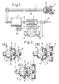
- a main shaft 1 of a balancing machine is shown.
- a motor vehicle wheel 13 clamped onto the main shaft.
- a drive motor 2 which is designed as an electric motor and in particular a capacitor motor (EP 0 524 465 B1) or other suitable AC motor, which is also used as a countercurrent brake.
- This drive motor 2 is further used to provide the force or the torque with which the motor vehicle wheel 13 is fixed to the main shaft and is released from the clamped state after carrying out the imbalance measurement and unbalance compensation.
- the clamping device 4 may be formed in a known manner. Possible embodiments are shown in FIG. 2 in the illustrations (A), (B) and (C). In the embodiments (A) and (B) takes place Mittenlochzentritation the motor vehicle wheel 13 by means of a mounted on the main shaft 1 centering cone 15. When tightening the center hole of the motor vehicle wheel 13 is pushed onto this centering cone 15. With the aid of a clamping nut 5, to which an impeller 14 in the embodiment (A) and a handwheel 6 in the embodiment in the illustration (B) is formed, the wheel 13 is pressed against a flange 16. The clamping nut 5 is in threaded engagement with a thread 7 which is rotatably connected to the clamping shaft 1. Between the clamping nut and the motor vehicle wheel 13, a pressure pot 17 may be provided for receiving the wheel voltage.
- Fig. 2 (C) is connected between the clamping nut 5 and the motor vehicle wheel 13, a removable flange 18 with centering pins 19
- the centering engage with conically shaped front ends in the bolt holes of the vehicle wheel.
- the centering pins 19 can be brought to the exchange flange 18 at different radii or replaced.
- the main shaft 1 and the rotatably connected thread 7 is rotated while the clamping nut 5 is held against rotation, for example on the handwheel 6 or the impeller 14.
- the holding can be done by hand or with the help of a not shown machine frame supported Garelnraum 22, which can be brought into engagement with the clamping device 4 (Fig. 1).
- the lock nut 5 held against rotation during clamping in the illustrations of FIG. 2 is shifted to the left, so that the motor vehicle wheel 13 is pressed against the respective flanges 16.
- Due to the action of the centering cones on the centering cone or on the centering pin 19, a centering of the vehicle wheel relative to the shaft axis 20 takes place.
- the main shaft 1 For driving the main shaft 1 provides the drive motor 2, which is turned on by means of a main switch 11 or other switch which is operated by means of a pedal.
- the main switch or the pedal-operated switch may be formed as a toggle switch, so that the drive motor 2 and thus the main shaft 1 can be driven in opposite directions.
- the clamping of the drive motor 2 is driven in such a way that due to the thread rotation 7, as already explained, the clamping nut 5 is moved in Fig. 2 to the left.
- the current drawn by the motor is measured to measure the torque.
- a corresponding torque measuring device 3 which may be designed as a measuring device for measuring the supply current, is provided. With the torque measuring device 3, a comparator 8 is connected.
- a torque setpoint generator for example in the form of a memory, is also connected to the comparator 8.
- the setpoint memory 9 the torque value is stored, which should not be exceeded during clamping.
- the comparator 8 supplies a signal to a switch 12, which switches off the power supply to the drive motor 2.
- the stored in the memory 9 torque setpoint is such that the motor vehicle wheel 13 is clamped with sufficient clamping force on the main shaft t by means of the clamping devices shown in FIG.
- the setpoint memory 9 is activated when switching on the drive motor 2 in the direction of rotation provided for clamping.
- the main switch 11 and operated with the pedal switch is actuated in the other direction, so that the main shaft 1 is driven in the opposite direction, wherein the clamping nut 5 is again held against rotation.
- a setpoint memory 10 is activated, in which a setpoint value for the torque is stored, in which the disconnection of the supply current during release by means of the drive motor 2 is to take place.
- the comparator 8 again provides the corresponding off signal to the switch 12. The clamping nut 5 is then solved that by hand in a simple manner for the final removal of the motor vehicle wheel 13 from the thread by turning Hand can be removed by the service person.
- a safety device can be provided which also switches off the motor when the clamping device 4 is not held fast.
- a timer 21 may be provided which predetermines a specific time interval beginning with the switching on of the drive motor 2. This time interval corresponds at least to the time interval which is required in order to clamp the wheel to be balanced with the required setpoint torque when the clamping device 4 is held fast.
- a signal for example from the timer 21, is generated, by which the drive motor 2 is switched off.
- the timer 21 may be connected to the switch 12. This shutdown effected by the timer 21 takes place in accordance with the operation of the comparator 8. If no shutdown is effected by the comparator 8 within the predetermined time interval, this is caused by the timer 21, as explained.
- a speed monitoring of the speed of the main shaft 1 can be performed. If the time course of the determined rotational speed does not correspond to the rotational speed profile which is present during a proper tensioning operation, the drive motor 2 is also switched off after a certain timeout.
Landscapes
- Physics & Mathematics (AREA)
- General Physics & Mathematics (AREA)
- Testing Of Balance (AREA)
Claims (7)
- Procédé destiné à fixer de manière démontable une roue (13) de véhicule automobile sur un arbre principal (1) d'une machine d'équilibrage de roues, selon lequel un trou central prévu sur la roue et/ou des trous de goujons prévus sur la roue (13) sont serrés respectivement sur un ou plusieurs cônes de centrage (15 ; 19) disposés de manière définie par rapport à l'axe (20) de l'arbre principal, ou dégagés de ceux-ci, à l'aide d'un écrou de serrage (5) pouvant se déplacer dans la direction axiale sur l'arbre principal en y étant en prise par filetage,
caractérisé en ce que pour le déplacement axial de l'écrou de serrage (5), on fait tourner l'arbre principal (1) par l'entraînement du moteur (2), en immobilisant l'écrou de serrage (5) en rotation et
lorsque l'on atteint au cours de la phase de serrage, un couple engendré par l'entraînement du moteur à l'encontre de l'écrou de serrage (5) immobilisé tel que la roue de véhicule automobile est serrée suffisamment fort pour effectuer la mesure de balourd sur l'arbre principal, l'entraînement du moteur (2) est automatiquement arrêté. - Procédé selon la revendication 1, caractérisé en ce que l'entraînement du moteur (2) est arrêté lorsqu'à l'intérieur d'un intervalle de temps déterminé après la mise en marche de l'entraînement du moteur (2), le couple engendré par l'entraînement du moteur reste en-dessous d'un couple de consigne.
- Procédé selon la revendication 1 ou 2, caractérisé en ce que le couple engendré par l'entraînement du moteur (2) à l'encontre de l'écrou de serrage (5) immobilisé, est comparé à un couple de consigne.
- Dispositif destiné à fixer de manière démontable une roue (13) de véhicule automobile sur un arbre principal (1) d'une machine d'équilibrage, qui peut être entraîné par un moteur d'entraînement (2), et comprenant un ou plusieurs cônes de centrage (15 ; 19) disposés de manière définie par rapport à l'axe (20) de l'arbre principal et un écrou de serrage (5) mobile dans la direction axiale en étant en prise par filetage avec l'arbre principal (1), un trou central prévu sur la roue et/ou des trous de goujons prévus sur la roue (13) étant serrés sur le cône de centrage ou respectivement les cônes de centrage (15 ; 19) ou dégagés de celui-ci ou de ceux-ci,
caractérisé en ce que sur l'écrou de serrage (5) est prévu un système (6 ; 14) pour immobiliser l'écrou de serrage (5) en rotation, à la main ou par un dispositif de retenue (22) pouvant s'appuyer sur le châssis de la machine, et en ce qu'un dispositif de commutation (11, 12) du moteur d'entraînement (2) de l'arbre principal (1) est conçu de façon telle, et le moteur d'entraînement (2) est relié à l'arbre principal (1) de façon telle, que lors du serrage de la roue (13) du véhicule automobile, sur le cône de centrage ou les cônes de centrage (15 ; 19), le moteur d'entraînement (2) peut être mis en marche pour faire tourner l'arbre principal (1) et déplacer axialement l'écrou de serrage (5) immobilisé en rotation et le dispositif de commutation (11, 12) comprend un commutateur (12) destiné à arrêter automatiquement le moteur d'entraînement (2), qui est en marche lors du serrage de la roue (13) de véhicule automobile sur le cône de centrage ou les cônes de centrage (15 ; 19), lorsque l'on atteint un couple tel que la roue de véhicule automobile est serrée suffisamment fort pour effectuer la mesure de balourd sur l'arbre principal. - Dispositif selon la revendication 4, caractérisé en ce que pour desserrer la roue (13) l'arbre principal (1) entraîné par le moteur d'entraînement (2) présente un sens de rotation opposé à celui du serrage, pour un écrou de serrage (5) immobilisé en rotation.
- Dispositif selon la revendication 4 ou 5, caractérisé en ce qu'une mémoire de valeur de consigne (9, 10) pour un couple de consigne, rendue active par la mise en marche du moteur d'entraînement (2), est reliée à un comparateur (8) en vue de la comparaison avec le couple engendré par le moteur d'entraînement (2) à l'encontre de l'écrou de serrage (5) maintenu immobilisé .
- Dispositif selon l'une revendications 4 à 6, caractérisé en ce qu'une horloge (21) prescrivant un intervalle de temps durant lequel est atteint le couple de consigne engendré par le moteur d'entraînement (2) à l'encontre de l'écrou de serrage (5) maintenu immobilisé, est reliée au commutateur (12) pour arrêter automatiquement le moteur d'entraînement (2).
Applications Claiming Priority (2)
| Application Number | Priority Date | Filing Date | Title |
|---|---|---|---|
| DE19713075 | 1997-03-27 | ||
| DE19713075A DE19713075B4 (de) | 1997-03-27 | 1997-03-27 | Verfahren und Vorrichtung zum lösbaren Befestigen eines Kraftfahrzeugrades an einer von einem Antriebsmotor antreibbaren Hauptwelle einer Radauswuchtmaschine |
Publications (4)
| Publication Number | Publication Date |
|---|---|
| EP0867706A2 EP0867706A2 (fr) | 1998-09-30 |
| EP0867706A3 EP0867706A3 (fr) | 1999-08-18 |
| EP0867706B1 EP0867706B1 (fr) | 2002-02-13 |
| EP0867706B2 true EP0867706B2 (fr) | 2007-02-28 |
Family
ID=7824916
Family Applications (1)
| Application Number | Title | Priority Date | Filing Date |
|---|---|---|---|
| EP98103943A Expired - Lifetime EP0867706B2 (fr) | 1997-03-27 | 1998-03-05 | Méthode et dispositif pour fixer une roue de véhicule sur l'arbre principale d'une machine d'équilibrage |
Country Status (4)
| Country | Link |
|---|---|
| US (1) | US5948980A (fr) |
| EP (1) | EP0867706B2 (fr) |
| DE (1) | DE19713075B4 (fr) |
| ES (1) | ES2172046T3 (fr) |
Families Citing this family (12)
| Publication number | Priority date | Publication date | Assignee | Title |
|---|---|---|---|---|
| US6324908B1 (en) | 1996-01-31 | 2001-12-04 | Hunter Engineering Company | Wheel balancer and control circuit therefor |
| US6338273B1 (en) * | 1999-07-27 | 2002-01-15 | Hawek Auswuchetechnik Horst Warkotsch Gmbh | Clamping device for fixing a wheel rim of a vehicle wheel to a shaft of a balancing machine |
| US6772631B2 (en) | 2001-08-31 | 2004-08-10 | Allan H. Hansen | Vehicle wheel balancer |
| US6619120B2 (en) | 2001-09-19 | 2003-09-16 | Allan H. Hansen | Wheel mounting member for vehicle wheel balancer |
| DE10238271B4 (de) * | 2002-08-21 | 2012-11-08 | Snap-On Equipment Gmbh | Verfahren und Vorrichtung zum zentrierten Spannen eines Kraftfahrzeugrades auf eine Hauptwelle einer Radauswuchtmaschine |
| US7077006B2 (en) * | 2003-02-04 | 2006-07-18 | Hansen Allan H | High-accuracy wheel spacer |
| RU2240522C1 (ru) * | 2003-02-20 | 2004-11-20 | Государственное учреждение Кузбасский государственный технический университет | Приспособление для статической балансировки |
| US6854194B2 (en) | 2003-04-23 | 2005-02-15 | Allan H. Hansen | Wheel centering adaptor with protective liner and wear indicator |
| US20050038580A1 (en) * | 2003-08-15 | 2005-02-17 | Seim Kerri Jean | Information about structural integrity of vehicles |
| US20050109106A1 (en) * | 2003-11-26 | 2005-05-26 | Hansen Allan H. | Two-piece centering stud for a vehicle wheel balancer |
| EP3418708B1 (fr) | 2017-06-23 | 2021-04-07 | Snap-on Equipment Srl a unico socio | Équilibreuse de roue avec servomoteur |
| DE102017114018B4 (de) * | 2017-06-23 | 2021-01-07 | Snap-On Equipment Srl A Unico Socio | Radservicemaschine mit Krafterfassungseinrichtung |
Citations (1)
| Publication number | Priority date | Publication date | Assignee | Title |
|---|---|---|---|---|
| EP0877920A1 (fr) † | 1996-01-31 | 1998-11-18 | Hunter Engineering Company | Equilibreuse de roues a servomoteur |
Family Cites Families (7)
| Publication number | Priority date | Publication date | Assignee | Title |
|---|---|---|---|---|
| US4085619A (en) * | 1976-02-09 | 1978-04-25 | Royal Industries, Inc. | Electronic balancer for vehicle wheels |
| US4332169A (en) * | 1980-06-16 | 1982-06-01 | Hennessy Industries, Inc. | Speed nut for a wheel balancer |
| DE3730083A1 (de) * | 1987-09-08 | 1989-03-16 | Hofmann Werkstatt Technik | Vorrichtung zum messen von unwuchten an rotoren |
| DE3923191C2 (de) * | 1989-07-13 | 1994-02-24 | Hofmann Werkstatt Technik | Vorrichtung zum Messen der Unwucht eines Rotors, insbesondere eines Kraftfahrzeugrades |
| DE4124285C2 (de) * | 1991-07-22 | 2001-04-26 | Snap On Deutschland Holding | Vorrichtung zum Messen der Unwucht eines Rotors |
| DE4200380C2 (de) * | 1992-01-09 | 1996-09-19 | Hofmann Werkstatt Technik | Verfahren und Vorrichtung zum Spannen und Lösen eines Rotors, insbesondere eines Kraftfahrzeugrades, an einer von einem Motor angetriebenen Hauptwelle einer Unwuchtmeßanordnung, insbesondere einer Radauswuchtmaschine |
| US5385045A (en) * | 1992-07-15 | 1995-01-31 | Fmc Corporation | Tire changing and balancing machine |
-
1997
- 1997-03-27 DE DE19713075A patent/DE19713075B4/de not_active Expired - Lifetime
-
1998
- 1998-03-05 ES ES98103943T patent/ES2172046T3/es not_active Expired - Lifetime
- 1998-03-05 EP EP98103943A patent/EP0867706B2/fr not_active Expired - Lifetime
- 1998-03-27 US US09/049,050 patent/US5948980A/en not_active Expired - Lifetime
Patent Citations (1)
| Publication number | Priority date | Publication date | Assignee | Title |
|---|---|---|---|---|
| EP0877920A1 (fr) † | 1996-01-31 | 1998-11-18 | Hunter Engineering Company | Equilibreuse de roues a servomoteur |
Non-Patent Citations (1)
| Title |
|---|
| Firmenprospekt der Firma Hofmann Werkstatt-Technik GmbH, Pfungstadt, geodyna 5001, geodyna 5501, Impressum 950211406.98 † |
Also Published As
| Publication number | Publication date |
|---|---|
| EP0867706B1 (fr) | 2002-02-13 |
| ES2172046T3 (es) | 2002-09-16 |
| DE19713075A1 (de) | 1998-10-01 |
| EP0867706A2 (fr) | 1998-09-30 |
| US5948980A (en) | 1999-09-07 |
| DE19713075B4 (de) | 2004-09-16 |
| EP0867706A3 (fr) | 1999-08-18 |
Similar Documents
| Publication | Publication Date | Title |
|---|---|---|
| EP0550816B1 (fr) | Méthode et dispositif pour serrer et débloquer un rotor d'un arbre principal entraîné par un moteur d'un arrangement d'équilibrage | |
| EP0867706B2 (fr) | Méthode et dispositif pour fixer une roue de véhicule sur l'arbre principale d'une machine d'équilibrage | |
| EP1333265B1 (fr) | Mesure du balourd dune roue de motocyclette avec un détachement du dispositif d'entraínement par un changement soudain de la vitesse de rotation | |
| DE2914844C2 (de) | Schnellspannvorrichtung, insbesondere für Auswuchtmaschinen zum Auswuchten von Fahrzeugrädern | |
| DE4308711C2 (de) | Vorrichtung zum Verfahren von auf Schlitten befestigten und Wellen lagernden Lagerböcken | |
| DE2807343A1 (de) | Selbstzentrierende vorrichtung zur befestigung eines fahrzeugrades auf der achse einer auswuchtmaschine | |
| EP2114702B1 (fr) | Dispositif de montage et procédé de montage et de démontage d'un pneumatique de véhicule sur une jante | |
| EP1708942B1 (fr) | Changeur de bobines | |
| DE69901662T2 (de) | Maschinen zum Verdrillen von Stäben mit vieleckigem Querschnitt | |
| EP0650042A2 (fr) | Procédé et dispositif de maintien en position d'une roue de véhicule serrée sur un axe de mesure d'une machine d'équilibrage | |
| DE3923191C2 (de) | Vorrichtung zum Messen der Unwucht eines Rotors, insbesondere eines Kraftfahrzeugrades | |
| EP3568264A1 (fr) | Dispositif de serrage destiné à serrer un ressort hélicoïdale | |
| DE2435534A1 (de) | Maschine zum kaltverwinden von laenglichen profil-werkstuecken | |
| DE4205045C1 (en) | Pneumatic tyre fitting device for vehicle wheel - uses current amplitude regulation of drive motor to control torque during fitting process | |
| EP0988516A1 (fr) | Mandrin a serrage rapide pour fixer la jante d'une roue de vehicule sur l'extremite a filet exterieur de l'arbre d'une machine a equilibrer | |
| DE10238271B4 (de) | Verfahren und Vorrichtung zum zentrierten Spannen eines Kraftfahrzeugrades auf eine Hauptwelle einer Radauswuchtmaschine | |
| DE9308945U1 (de) | Vorrichtung zur Demontage eines Reifens von einer Felge | |
| DE102004017767B4 (de) | Verfahren und Vorrichtung zum Auswuchten eines Fahrzeugrades | |
| DE3432753C2 (fr) | ||
| DE4231841C2 (de) | "Spannvorrichtung" | |
| DE102019111511A1 (de) | Druckwerk für eine Offsetdruckmaschine mit einem mindestens ein Gummituch tragenden Gummizylinder und Verfahren zum Handhaben eines Gummituches | |
| EP3962743B1 (fr) | Cylindre de blanchet et procédé de manipulation d'un blanchet | |
| WO1989001898A1 (fr) | Dispositif de ficelage automatique de rouleaux | |
| EP1331472A2 (fr) | Procédé et dispositif d'équilibrage d'une roue de véhicule | |
| DE102024121851A1 (de) | Maschine und Verfahren zum automatisierten Montieren von Speichenrädern, insbesondere Laufrädern von Fahrrädern |
Legal Events
| Date | Code | Title | Description |
|---|---|---|---|
| PUAI | Public reference made under article 153(3) epc to a published international application that has entered the european phase |
Free format text: ORIGINAL CODE: 0009012 |
|
| AK | Designated contracting states |
Kind code of ref document: A2 Designated state(s): ES FR GB IT |
|
| AX | Request for extension of the european patent |
Free format text: AL;LT;LV;MK;RO;SI |
|
| PUAL | Search report despatched |
Free format text: ORIGINAL CODE: 0009013 |
|
| AK | Designated contracting states |
Kind code of ref document: A3 Designated state(s): AT BE CH DE DK ES FI FR GB GR IE IT LI LU MC NL PT |
|
| AX | Request for extension of the european patent |
Free format text: AL;LT;LV;MK;RO;SI |
|
| RIC1 | Information provided on ipc code assigned before grant |
Free format text: 6G 01M 1/06 A, 6G 01M 1/04 B |
|
| 17P | Request for examination filed |
Effective date: 20000128 |
|
| RAP1 | Party data changed (applicant data changed or rights of an application transferred) |
Owner name: SNAP-ON DEUTSCHLAND HOLDING GMBH |
|
| AKX | Designation fees paid |
Free format text: ES FR GB IT |
|
| REG | Reference to a national code |
Ref country code: DE Ref legal event code: 8566 |
|
| 17Q | First examination report despatched |
Effective date: 20001110 |
|
| GRAG | Despatch of communication of intention to grant |
Free format text: ORIGINAL CODE: EPIDOS AGRA |
|
| GRAG | Despatch of communication of intention to grant |
Free format text: ORIGINAL CODE: EPIDOS AGRA |
|
| GRAH | Despatch of communication of intention to grant a patent |
Free format text: ORIGINAL CODE: EPIDOS IGRA |
|
| GRAH | Despatch of communication of intention to grant a patent |
Free format text: ORIGINAL CODE: EPIDOS IGRA |
|
| GRAA | (expected) grant |
Free format text: ORIGINAL CODE: 0009210 |
|
| REG | Reference to a national code |
Ref country code: GB Ref legal event code: IF02 |
|
| AK | Designated contracting states |
Kind code of ref document: B1 Designated state(s): ES FR GB IT |
|
| GBT | Gb: translation of ep patent filed (gb section 77(6)(a)/1977) |
Effective date: 20020215 |
|
| ET | Fr: translation filed | ||
| RAP2 | Party data changed (patent owner data changed or rights of a patent transferred) |
Owner name: SNAP-ON EQUIPMENT GMBH |
|
| REG | Reference to a national code |
Ref country code: ES Ref legal event code: FG2A Ref document number: 2172046 Country of ref document: ES Kind code of ref document: T3 |
|
| PLBQ | Unpublished change to opponent data |
Free format text: ORIGINAL CODE: EPIDOS OPPO |
|
| PLBI | Opposition filed |
Free format text: ORIGINAL CODE: 0009260 |
|
| PLBF | Reply of patent proprietor to notice(s) of opposition |
Free format text: ORIGINAL CODE: EPIDOS OBSO |
|
| 26 | Opposition filed |
Opponent name: HUNTER ENGINEERING CO., Effective date: 20021113 |
|
| PLBF | Reply of patent proprietor to notice(s) of opposition |
Free format text: ORIGINAL CODE: EPIDOS OBSO |
|
| PGFP | Annual fee paid to national office [announced via postgrant information from national office to epo] |
Ref country code: FR Payment date: 20040318 Year of fee payment: 7 |
|
| PGFP | Annual fee paid to national office [announced via postgrant information from national office to epo] |
Ref country code: ES Payment date: 20040324 Year of fee payment: 7 |
|
| APBP | Date of receipt of notice of appeal recorded |
Free format text: ORIGINAL CODE: EPIDOSNNOA2O |
|
| APBQ | Date of receipt of statement of grounds of appeal recorded |
Free format text: ORIGINAL CODE: EPIDOSNNOA3O |
|
| APAA | Appeal reference recorded |
Free format text: ORIGINAL CODE: EPIDOS REFN |
|
| PG25 | Lapsed in a contracting state [announced via postgrant information from national office to epo] |
Ref country code: ES Free format text: LAPSE BECAUSE OF NON-PAYMENT OF DUE FEES Effective date: 20050307 |
|
| PGFP | Annual fee paid to national office [announced via postgrant information from national office to epo] |
Ref country code: GB Payment date: 20050321 Year of fee payment: 8 |
|
| APAH | Appeal reference modified |
Free format text: ORIGINAL CODE: EPIDOSCREFNO |
|
| PG25 | Lapsed in a contracting state [announced via postgrant information from national office to epo] |
Ref country code: FR Free format text: LAPSE BECAUSE OF NON-PAYMENT OF DUE FEES Effective date: 20051130 |
|
| REG | Reference to a national code |
Ref country code: FR Ref legal event code: ST Effective date: 20051130 |
|
| PG25 | Lapsed in a contracting state [announced via postgrant information from national office to epo] |
Ref country code: GB Free format text: LAPSE BECAUSE OF NON-PAYMENT OF DUE FEES Effective date: 20060305 |
|
| REG | Reference to a national code |
Ref country code: ES Ref legal event code: FD2A Effective date: 20050307 |
|
| APBU | Appeal procedure closed |
Free format text: ORIGINAL CODE: EPIDOSNNOA9O |
|
| GBPC | Gb: european patent ceased through non-payment of renewal fee |
Effective date: 20060305 |
|
| PUAH | Patent maintained in amended form |
Free format text: ORIGINAL CODE: 0009272 |
|
| STAA | Information on the status of an ep patent application or granted ep patent |
Free format text: STATUS: PATENT MAINTAINED AS AMENDED |
|
| 27A | Patent maintained in amended form |
Effective date: 20070228 |
|
| AK | Designated contracting states |
Kind code of ref document: B2 Designated state(s): ES FR GB IT |
|
| REG | Reference to a national code |
Ref country code: ES Ref legal event code: FD2A Effective date: 20050307 |
|
| EN | Fr: translation not filed | ||
| PGFP | Annual fee paid to national office [announced via postgrant information from national office to epo] |
Ref country code: IT Payment date: 20150330 Year of fee payment: 18 |
|
| PG25 | Lapsed in a contracting state [announced via postgrant information from national office to epo] |
Ref country code: IT Free format text: LAPSE BECAUSE OF NON-PAYMENT OF DUE FEES Effective date: 20160305 |