EP0867710B1 - Faserdetektor für ein Messgerät zur Bestimmung der Lichtstreuung - Google Patents
Faserdetektor für ein Messgerät zur Bestimmung der Lichtstreuung Download PDFInfo
- Publication number
- EP0867710B1 EP0867710B1 EP98105460A EP98105460A EP0867710B1 EP 0867710 B1 EP0867710 B1 EP 0867710B1 EP 98105460 A EP98105460 A EP 98105460A EP 98105460 A EP98105460 A EP 98105460A EP 0867710 B1 EP0867710 B1 EP 0867710B1
- Authority
- EP
- European Patent Office
- Prior art keywords
- light
- mode
- fiber
- detector
- optical fibre
- Prior art date
- Legal status (The legal status is an assumption and is not a legal conclusion. Google has not performed a legal analysis and makes no representation as to the accuracy of the status listed.)
- Expired - Lifetime
Links
- 239000000835 fiber Substances 0.000 title claims description 49
- 238000000149 argon plasma sintering Methods 0.000 title description 3
- 239000013307 optical fiber Substances 0.000 claims abstract description 51
- 230000003287 optical effect Effects 0.000 claims abstract description 17
- 238000002296 dynamic light scattering Methods 0.000 claims description 16
- 230000003068 static effect Effects 0.000 claims description 9
- 238000001370 static light scattering Methods 0.000 claims description 9
- 230000036961 partial effect Effects 0.000 abstract description 3
- 230000008878 coupling Effects 0.000 abstract 1
- 238000010168 coupling process Methods 0.000 abstract 1
- 238000005859 coupling reaction Methods 0.000 abstract 1
- 238000005259 measurement Methods 0.000 description 7
- 239000013598 vector Substances 0.000 description 7
- 238000001514 detection method Methods 0.000 description 6
- 239000002245 particle Substances 0.000 description 6
- 238000011835 investigation Methods 0.000 description 5
- 239000000523 sample Substances 0.000 description 5
- 230000000694 effects Effects 0.000 description 2
- 230000002123 temporal effect Effects 0.000 description 2
- 230000005653 Brownian motion process Effects 0.000 description 1
- 238000004458 analytical method Methods 0.000 description 1
- 238000005537 brownian motion Methods 0.000 description 1
- 230000002950 deficient Effects 0.000 description 1
- 238000009792 diffusion process Methods 0.000 description 1
- 238000009826 distribution Methods 0.000 description 1
- 238000002474 experimental method Methods 0.000 description 1
- 239000004973 liquid crystal related substance Substances 0.000 description 1
- 238000004519 manufacturing process Methods 0.000 description 1
- 238000000691 measurement method Methods 0.000 description 1
- 238000000034 method Methods 0.000 description 1
- 238000005457 optimization Methods 0.000 description 1
- 230000010287 polarization Effects 0.000 description 1
- 239000012488 sample solution Substances 0.000 description 1
- 238000010183 spectrum analysis Methods 0.000 description 1
- 230000036962 time dependent Effects 0.000 description 1
Images
Classifications
-
- G—PHYSICS
- G01—MEASURING; TESTING
- G01N—INVESTIGATING OR ANALYSING MATERIALS BY DETERMINING THEIR CHEMICAL OR PHYSICAL PROPERTIES
- G01N15/00—Investigating characteristics of particles; Investigating permeability, pore-volume or surface-area of porous materials
- G01N15/02—Investigating particle size or size distribution
- G01N15/0205—Investigating particle size or size distribution by optical means
-
- G—PHYSICS
- G01—MEASURING; TESTING
- G01N—INVESTIGATING OR ANALYSING MATERIALS BY DETERMINING THEIR CHEMICAL OR PHYSICAL PROPERTIES
- G01N21/00—Investigating or analysing materials by the use of optical means, i.e. using sub-millimetre waves, infrared, visible or ultraviolet light
- G01N21/17—Systems in which incident light is modified in accordance with the properties of the material investigated
- G01N21/47—Scattering, i.e. diffuse reflection
- G01N21/4738—Diffuse reflection, e.g. also for testing fluids, fibrous materials
- G01N21/474—Details of optical heads therefor, e.g. using optical fibres
Definitions
- the invention relates to a fiber detector for a Measuring device for determining the static and / or dynamic Light scattering.
- Detectors for determining the static and / or the dynamic light scattering in which optical fibers are used will find because of the simplicity of their structure and their Alignment multiple application. Compared to the classic Pinhole detectors result in fiber detectors their property, only a few transverse modes from the to select the total scattered light of a sample, a higher one Light intensity with better coherence of the captured Light. Although a complete theory of light propagation very much in an optical fiber for multimode optical fibers complicated, it is sufficient to assume for practical purposes that all modes are lossless in an optical fiber and spread orthogonally to each other. Leaving aside side effects eight, then the optical fiber can be used as a bundle of individual, separate, single-mode fibers that are apparently different from each other for each used wavelength typical mode field diameter are separated. Such a fiber is said to be an ideal optical one Fiber.
- the temporal change in the intensity of the of the scattered light of scattered light is the temporal change in the intensity of the of the scattered light of scattered light, which occurs in a defined scatter vector q.
- the temporal Changes in the intensity of the scattered light are caused by the spatial movement of the dissolved particles towards each other. That from every particle has scattered light at the point of its detection a defined phase, which depends on its position and on the The sum of all scatter contributions of the particles in the solution depends. Since the change of location of the particles is thermal induced Brownian motion are the position changes completely random as well as the phase changes and that resulting optical field at the observation point.
- the lowest limit of the ratio of fluctuating Signal component to the constant signal component would be a complete incoherent or multimode detection. While the Total intensity of the scattered light with each additional selected fashion grows accordingly, the fluctuating Portion of the signal quickly averaged down to near 0, the resulting product of intercept and light intensity is a parameter that is ideal for optical Fiber is a constant.
- intercept fiber 1 N
- Intensity pinhole ⁇ N the number of modes selected [J. Ricka, Dynamic Light Scattering with Single Mode and Multi-mode Receivers, Applied Optics 32, 2860-2875 (1993)].
- the desired optimal intercept of 0.8 cannot therefore a single optical fiber, but only with a three-mode optical fiber, which together with additional, the diffraction-limiting devices are used, such as perforated disks. However, there is a considerable difference cher portion of the light lost.
- any light intensity between 1 and 3 (when using a three-mode optical fiber) or any light intensity between 1 and 6 (when using a six-mode optical fiber) is achieved according to the invention if a known device for splitting a uniform Light beam is connected to one with several light beams new device that allows single modes from one select multi-mode light beam and by mixing different modes a light beam with the desired very special optical intensity.
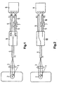
- a fiber detector according to the invention for a measuring device for determining the dynamic Achieve light scattering, using a multi-mode optical Fiber 4 first with a device 9 for splitting the Light in two light beams of the same or different Intensity is connected and then each of the light rays from a multimode optical fiber 5 is received, wherein one of these multimode optical fibers via a fiber connector 7 with a single-mode optical fiber 6 is linked and both optical fibers then mixed of light are connected to a single photon detector 8.
- Fig. 1 the laser beam 1 illuminates the sample 2, the stray light by a Focusing device 3 introduced into a three-mode optical fiber (F1) 4 becomes.
- the device for splitting the light 9 From there it will Light into the device for splitting the light 9 directed that the uniform light beam into two light beams with 12% or 88% of the original light intensity disassembled.
- the light beam with the light intensity of 12% leaves the device for splitting the light over a three-mode optical fiber (F2) 5 using the single photon detector 8, usually a photomultiplier or one Photodiode, is connected.
- the Light beam by means of the high-precision fiber connector 7 with the optical fiber (F3) 6 linked, which is only a single mode which also has the single photon detector 8 connected is.
- the required for the laser detector according to the invention is three-mode, six-mode or ten-mode optical fiber a commercially available optical fiber that according to Core diameter, numerical aperture and wavelength of the applied light is selected so that there are three in it Can spread fashions.
- an optical one Fiber can be selected that guide six or ten light modes can.
- connection of a three-mode fiber with a single-mode optical fiber for forwarding a fashion is almost lossless if the numerical apertures in both fibers are about the same. In the event of a defective fiber connection however, losses can occur. However, since the Light intensity along the axis of the fiber core depends on the Gaussian distribution curve, the losses are almost always low.
- any mode value can be set between 1 and 3.
- F1 is a three-mode fiber Gap ratio for F3 (%) Gap ratio for F2 (%)
- Botinterzept Total light intensity 99 1 0.980 1.02 95 5 0.909 1.10 90 10 0,833 1.20 85 15 0.769 1.30 80 20 0.714 1.40 70 30 0.625 1.60 60 40 0.556 1.80 50 50 0,500 2.00 40 60 0,455 2.20 30 70 0,417 2.40 20 80 0.385 2.60 10 90 0,357 2.80 5 95 0.345 2.90 1 99 0,336 2.98
- Table 2 shows the measurement results when F1 is a six-mode fiber. With different gap ratios for F3 and F2, the specified values for the overall concept and the total light intensity were measured: F1 is a six-mode fiber Gap ratio for F3 (%) Gap ratio for F2 (%) Automatinterzept Total light intensity (compared to a single-mode fiber) 99 1 0,952 1.05 95 5 0,800 1.25 90 10 0,667 1.50 85 15 0.571 1.75 80 20 0,500 2.00 70 30 0,400 2.50 60 40 0.333 3.00 50 50 0.286 3.50 40 60 0,250 4.00 30 70 0.222 4.50 20 80 0,200 5.00 10 90 0.182 5.50 5 95 0.174 5.75 1 99 0.168 5.95
- a device to split the light that allows variable gap ratios for example a liquid crystal retarder with a Glan prism polarization cube, can replace fixed gaps the full range of intercepts and of yourself resulting total intensities with a single structure can be determined without any optical parts need to be replaced.
- a fiber detector can also be used according to the invention be used in place of the device for optical Splitting the light 9 an optical switch 10 contains the light either via a multi-mode optical Fiber 5 or via a multimode optical fiber 5, the by means of a fiber connector 7 with a single-mode optical Fiber 6 is linked and then the light to the single photon detector 8 forward.
- an optical switch 10 contains the light either via a multi-mode optical Fiber 5 or via a multimode optical fiber 5, the by means of a fiber connector 7 with a single-mode optical Fiber 6 is linked and then the light to the single photon detector 8 forward.
- a device can the static and the dynamic practically simultaneously Light scattering can be measured by a for a measuring time t high intercept is used to the dynamic light scattering to determine and then toggled to at high To measure the static light scattering (Fig. 2).
- a six-mode optical fiber is used, is the total intensity of the static scattered light six times greater than the intensity of dynamic light scattering. The has the consequence that the measuring time with the same accuracy is six times
Landscapes
- Chemical & Material Sciences (AREA)
- Biochemistry (AREA)
- Physics & Mathematics (AREA)
- Health & Medical Sciences (AREA)
- Life Sciences & Earth Sciences (AREA)
- Analytical Chemistry (AREA)
- General Health & Medical Sciences (AREA)
- General Physics & Mathematics (AREA)
- Immunology (AREA)
- Pathology (AREA)
- Dispersion Chemistry (AREA)
- Investigating Or Analysing Materials By Optical Means (AREA)
- Investigating Or Analysing Materials By The Use Of Chemical Reactions (AREA)
- Spectrometry And Color Measurement (AREA)
Description
- Fig. 1
- zeigt einen erfindungsgemäßen Faserdetektor für ein Interzept = 0,8 mit einer Vorrichtung (9) zur Aufspaltung des Lichts in zwei Teilstrahlen.
- Fig. 2
- zeigt einen erfindungsgemäßen Faserdetektor mit einem optischen Umschalter (10), durch den das Licht wahlweise über eine mehrmodige optische Faser (5) oder über eine mit einer einmodigen Faser verknüpfte mehrmodige Faser geleitet werden kann.
| F1 ist eine dreimodige Faser | |||
| Spaltverhältnis für F3 (%) | Spaltverhältnis für F2 (%) | Gesamtinterzept | Gesamtlichtintensität (verglichen mit einer einmodigen Faser) |
| 99 | 1 | 0,980 | 1,02 |
| 95 | 5 | 0,909 | 1,10 |
| 90 | 10 | 0,833 | 1,20 |
| 85 | 15 | 0,769 | 1,30 |
| 80 | 20 | 0,714 | 1,40 |
| 70 | 30 | 0,625 | 1,60 |
| 60 | 40 | 0,556 | 1,80 |
| 50 | 50 | 0,500 | 2,00 |
| 40 | 60 | 0,455 | 2,20 |
| 30 | 70 | 0,417 | 2,40 |
| 20 | 80 | 0,385 | 2,60 |
| 10 | 90 | 0,357 | 2,80 |
| 5 | 95 | 0,345 | 2,90 |
| 1 | 99 | 0,336 | 2,98 |
| F1 ist eine sechsmodige Faser | |||
| Spaltverhältnis für F3 (%) | Spaltverhältnis für F2 (%) | Gesamtinterzept | Gesamtlichtintensität (verglichen mit einer einmodigen Faser) |
| 99 | 1 | 0,952 | 1,05 |
| 95 | 5 | 0,800 | 1,25 |
| 90 | 10 | 0,667 | 1,50 |
| 85 | 15 | 0,571 | 1,75 |
| 80 | 20 | 0,500 | 2,00 |
| 70 | 30 | 0,400 | 2,50 |
| 60 | 40 | 0,333 | 3,00 |
| 50 | 50 | 0,286 | 3,50 |
| 40 | 60 | 0,250 | 4,00 |
| 30 | 70 | 0,222 | 4,50 |
| 20 | 80 | 0,200 | 5,00 |
| 10 | 90 | 0,182 | 5,50 |
| 5 | 95 | 0,174 | 5,75 |
| 1 | 99 | 0,168 | 5,95 |
- 1
- Laserstrahl
- 2
- Probe
- 3
- Fokussiereinrichtung
- 4
- mehrmodige optische Faser (F1)
- 5
- mehrmodige optische Faser (F2)
- 6
- einmodige optische Faser (F3)
- 7
- Faserverbinder
- 8
- Einzelphotonendetektor
- 9
- Vorrichtung zum Aufspalten des Lichtes
- 10
- optischer Umschalter
Claims (2)
- Faserdetektor für ein Messgerät zur Bestimmung der dynamischen Lichtstreuung enthaltend eine mehrmodige optische Faser (4) und einen Photonendetektor (8), durch gekennzeichnet, dass die mehrmodige optische Faser (4) zunächst mit einer Vorrichtung (9) zur Aufspaltung des Lichtes in zwei Lichtstrahlen gleicher oder unterschiedlicher Intensität verbunden ist und jeder der Lichtstrahlen dann von einer mehrmodigen optischen Faser (5) aufgenommen wird, wobei eine dieser mehrmodigen optischen Fasern (5) über einen Faserverbinder (7) mit einer einmodigen optischen Faser (6) verknüpft ist und beide optischen Fasern dann unter Mischung des Lichtes mit einem Einzelphotonendetektor (8) verbunden sind.
- Faserdetektor für ein Messgerät zur Bestimmung der statischen und der dynamischen Lichtstreuung enthaltend eine mehrmodige optische Faser (4) und einen Photonendetektor (8), dadurch gekennzeichnet, dass die mehrmodige optische Faser (4) zunächst mit einem optischen Umschalter (10) verbunden ist, der das Licht wahlweise über eine mehrmodige optische Faser (5) oder über eine mehrmodige optische Faser (5) die mittels eines Faserverbinders (7) mit einer einmodigen optischen Faser (6) verknüpft ist, einem Einzelphotonendetektor (8) zuleitet.
Applications Claiming Priority (2)
| Application Number | Priority Date | Filing Date | Title |
|---|---|---|---|
| DE19713196 | 1997-03-28 | ||
| DE19713196A DE19713196C1 (de) | 1997-03-28 | 1997-03-28 | Faserdetektor für ein Meßgerät zur Bestimmung der Lichtstreuung |
Publications (2)
| Publication Number | Publication Date |
|---|---|
| EP0867710A1 EP0867710A1 (de) | 1998-09-30 |
| EP0867710B1 true EP0867710B1 (de) | 2003-09-17 |
Family
ID=7824981
Family Applications (1)
| Application Number | Title | Priority Date | Filing Date |
|---|---|---|---|
| EP98105460A Expired - Lifetime EP0867710B1 (de) | 1997-03-28 | 1998-03-26 | Faserdetektor für ein Messgerät zur Bestimmung der Lichtstreuung |
Country Status (3)
| Country | Link |
|---|---|
| EP (1) | EP0867710B1 (de) |
| AT (1) | ATE250222T1 (de) |
| DE (2) | DE19713196C1 (de) |
Families Citing this family (4)
| Publication number | Priority date | Publication date | Assignee | Title |
|---|---|---|---|---|
| KR20010084777A (ko) * | 2000-02-29 | 2001-09-06 | 윤종용 | 모드 커플링을 이용한 광 칩입자 감지 시스템 |
| DE10336080A1 (de) * | 2003-08-06 | 2005-03-03 | Gnothis Holding Sa | Verfahren und Vorrichtung zur Bestimmung von lumineszierenden Molekülen, insbesondere nach der Methode der Fluoreszenzkorrelationsspektroskopie |
| KR100803473B1 (ko) | 2006-02-06 | 2008-02-14 | 광주과학기술원 | 가변된 광주파수를 가지는 모드 사이 간섭현상을 이용한다중모드 광섬유의 모드간 지연시간 측정 시스템 |
| US10473591B2 (en) | 2017-05-01 | 2019-11-12 | Wyatt Technology Corporation | High throughput method and apparatus for measuring multiple optical properties of a liquid sample |
Family Cites Families (3)
| Publication number | Priority date | Publication date | Assignee | Title |
|---|---|---|---|---|
| US4818071A (en) * | 1985-03-26 | 1989-04-04 | Andrew Corporation | Fiber optic doppler anemometer |
| US5155549A (en) * | 1990-10-25 | 1992-10-13 | The Research Of State University Of New York | Method and apparatus for determining the physical properties of materials using dynamic light scattering techniques |
| DE29705625U1 (de) * | 1997-03-28 | 1997-05-28 | ALV-Laser Vertriebsgesellschaft mbH, 63225 Langen | Faserdetektor für ein Meßgerät zur Bestimmung der Lichtstreuung |
-
1997
- 1997-03-28 DE DE19713196A patent/DE19713196C1/de not_active Expired - Fee Related
-
1998
- 1998-03-26 AT AT98105460T patent/ATE250222T1/de not_active IP Right Cessation
- 1998-03-26 EP EP98105460A patent/EP0867710B1/de not_active Expired - Lifetime
- 1998-03-26 DE DE59809611T patent/DE59809611D1/de not_active Expired - Fee Related
Also Published As
| Publication number | Publication date |
|---|---|
| DE19713196C1 (de) | 1998-10-08 |
| ATE250222T1 (de) | 2003-10-15 |
| DE59809611D1 (de) | 2003-10-23 |
| EP0867710A1 (de) | 1998-09-30 |
Similar Documents
| Publication | Publication Date | Title |
|---|---|---|
| DE69629750T2 (de) | Teilchenanalysator mit einem aus zwei räumlich getrennten Elementen bestehenden optischen Filter | |
| DE60130356T2 (de) | Verfahren und vorrichtung zur bestimmung der polarisationseigenschaften von licht, das durch ein material emittiert, reflektiert oder durchgelassen wird, durch verwendung eines laser-scan-mikroskops | |
| EP0822395B1 (de) | Verfahren und Vorrichtung zur Raman-Korrelationsspektroskopie | |
| EP0961929B1 (de) | Lichtabtastvorrichtung | |
| DE69121633T2 (de) | Verfahren und Apparat zur Messung spektraler Absorption in undurchsichtigem Material und Verfahren und Apparat zur Messung einer Verteilung mikroskopischer Absorption | |
| DE3404608C2 (de) | ||
| DE69828345T2 (de) | Kreuzkorrelationsverfahren und Vorrichtung zur Unterdrückung der Effekte von Mehrfachstreuung | |
| EP0150035B1 (de) | Verfahren, Schaltungsanordnung und Einrichtung zur berührungslosen real-time-Bestimmung von Geschwindigkeiten sowie deren Verwendung | |
| DE19629725A1 (de) | Doppelobjektiv-System für ein Mikroskop, insbesondere Rastermikroskop | |
| DE19714202A1 (de) | Vorrichtung zum optischen Prüfen von Oberflächen | |
| DE4244605A1 (de) | Optisches Niederkohärenzreflektometer von verbesserter Empfindlichkeit mit optischer Dämpfung | |
| DE69631400T2 (de) | System für das Messen von Dünnfilmen | |
| DE4326473A1 (de) | Rastermikroskop zur Beobachtung unter einem Winkel zur Beleuchtung | |
| DE4035266C2 (de) | Verfahren und Anordnung zur Thermowellenanalyse | |
| DE102004051141A1 (de) | Dynamische Lichtstreumesseinrichtung unter Verwendung des Phasenmodulationsinterferenzverfahrens | |
| DE102011118607A1 (de) | Verfahren und Anordnung zur Streulichtmessung | |
| DE2936284C3 (de) | Ringinterferometer | |
| DE19713196C1 (de) | Faserdetektor für ein Meßgerät zur Bestimmung der Lichtstreuung | |
| DE3405886C2 (de) | Verfahren und Vorrichtung zum polarimetrischen Messen des Rollwinkels eines beweglichen Maschinenteiles | |
| DE69317874T2 (de) | Verfahren und vorrichtung zur differentiellen messung von brechungsindizes und deren anwendung | |
| DE102014216278A1 (de) | Vorrichtung zur interferometrischen Vermessung eines Objekts | |
| DE3106025C2 (de) | Verfahren und Vorrichtung zur schnellen Messung örtlicher Geschwindigkeitskomponenten in einem Geschwindigkeitsfeld | |
| DE60023443T2 (de) | Vorrichtung und Verfahren zur Überlagerungsempfang eines optischen Signals | |
| DE29705625U1 (de) | Faserdetektor für ein Meßgerät zur Bestimmung der Lichtstreuung | |
| DE60121746T2 (de) | Bildaufnahmeeinrichtung |
Legal Events
| Date | Code | Title | Description |
|---|---|---|---|
| PUAI | Public reference made under article 153(3) epc to a published international application that has entered the european phase |
Free format text: ORIGINAL CODE: 0009012 |
|
| AK | Designated contracting states |
Kind code of ref document: A1 Designated state(s): AT CH DE FR GB LI |
|
| AX | Request for extension of the european patent |
Free format text: AL;LT;LV;MK;RO;SI |
|
| 17P | Request for examination filed |
Effective date: 19990310 |
|
| AKX | Designation fees paid |
Free format text: AT BE CH DE DK LI |
|
| RBV | Designated contracting states (corrected) |
Designated state(s): AT CH DE FR GB LI |
|
| 17Q | First examination report despatched |
Effective date: 20020314 |
|
| GRAH | Despatch of communication of intention to grant a patent |
Free format text: ORIGINAL CODE: EPIDOS IGRA |
|
| GRAS | Grant fee paid |
Free format text: ORIGINAL CODE: EPIDOSNIGR3 |
|
| GRAA | (expected) grant |
Free format text: ORIGINAL CODE: 0009210 |
|
| AK | Designated contracting states |
Kind code of ref document: B1 Designated state(s): AT CH DE FR GB LI |
|
| REG | Reference to a national code |
Ref country code: GB Ref legal event code: FG4D Free format text: NOT ENGLISH |
|
| REG | Reference to a national code |
Ref country code: CH Ref legal event code: EP |
|
| REF | Corresponds to: |
Ref document number: 59809611 Country of ref document: DE Date of ref document: 20031023 Kind code of ref document: P |
|
| GBT | Gb: translation of ep patent filed (gb section 77(6)(a)/1977) |
Effective date: 20031211 |
|
| ET | Fr: translation filed | ||
| PLBE | No opposition filed within time limit |
Free format text: ORIGINAL CODE: 0009261 |
|
| STAA | Information on the status of an ep patent application or granted ep patent |
Free format text: STATUS: NO OPPOSITION FILED WITHIN TIME LIMIT |
|
| 26N | No opposition filed |
Effective date: 20040618 |
|
| PGFP | Annual fee paid to national office [announced via postgrant information from national office to epo] |
Ref country code: FR Payment date: 20060322 Year of fee payment: 9 |
|
| PGFP | Annual fee paid to national office [announced via postgrant information from national office to epo] |
Ref country code: CH Payment date: 20060324 Year of fee payment: 9 Ref country code: AT Payment date: 20060324 Year of fee payment: 9 |
|
| PGFP | Annual fee paid to national office [announced via postgrant information from national office to epo] |
Ref country code: DE Payment date: 20060331 Year of fee payment: 9 |
|
| REG | Reference to a national code |
Ref country code: CH Ref legal event code: PL |
|
| PG25 | Lapsed in a contracting state [announced via postgrant information from national office to epo] |
Ref country code: AT Free format text: LAPSE BECAUSE OF NON-PAYMENT OF DUE FEES Effective date: 20070326 |
|
| GBPC | Gb: european patent ceased through non-payment of renewal fee |
Effective date: 20070326 |
|
| REG | Reference to a national code |
Ref country code: FR Ref legal event code: ST Effective date: 20071130 |
|
| PG25 | Lapsed in a contracting state [announced via postgrant information from national office to epo] |
Ref country code: DE Free format text: LAPSE BECAUSE OF NON-PAYMENT OF DUE FEES Effective date: 20071002 |
|
| PG25 | Lapsed in a contracting state [announced via postgrant information from national office to epo] |
Ref country code: CH Free format text: LAPSE BECAUSE OF NON-PAYMENT OF DUE FEES Effective date: 20070331 Ref country code: LI Free format text: LAPSE BECAUSE OF NON-PAYMENT OF DUE FEES Effective date: 20070331 |
|
| PG25 | Lapsed in a contracting state [announced via postgrant information from national office to epo] |
Ref country code: GB Free format text: LAPSE BECAUSE OF NON-PAYMENT OF DUE FEES Effective date: 20070326 |
|
| PG25 | Lapsed in a contracting state [announced via postgrant information from national office to epo] |
Ref country code: FR Free format text: LAPSE BECAUSE OF NON-PAYMENT OF DUE FEES Effective date: 20070402 |
|
| PGFP | Annual fee paid to national office [announced via postgrant information from national office to epo] |
Ref country code: GB Payment date: 20060323 Year of fee payment: 9 |