EP0867736A2 - Verfahren und Vorrichtung zur Abstimmung der Wellenlänge und der Bandbreite eines optischen Gitters - Google Patents
Verfahren und Vorrichtung zur Abstimmung der Wellenlänge und der Bandbreite eines optischen Gitters Download PDFInfo
- Publication number
- EP0867736A2 EP0867736A2 EP98105350A EP98105350A EP0867736A2 EP 0867736 A2 EP0867736 A2 EP 0867736A2 EP 98105350 A EP98105350 A EP 98105350A EP 98105350 A EP98105350 A EP 98105350A EP 0867736 A2 EP0867736 A2 EP 0867736A2
- Authority
- EP
- European Patent Office
- Prior art keywords
- grating
- optical
- block
- temperature
- waveguide
- Prior art date
- Legal status (The legal status is an assumption and is not a legal conclusion. Google has not performed a legal analysis and makes no representation as to the accuracy of the status listed.)
- Withdrawn
Links
Images

Classifications
-
- G—PHYSICS
- G02—OPTICS
- G02B—OPTICAL ELEMENTS, SYSTEMS OR APPARATUS
- G02B6/00—Light guides; Structural details of arrangements comprising light guides and other optical elements, e.g. couplings
- G02B6/02—Optical fibres with cladding with or without a coating
- G02B6/02057—Optical fibres with cladding with or without a coating comprising gratings
- G02B6/02076—Refractive index modulation gratings, e.g. Bragg gratings
- G02B6/02195—Refractive index modulation gratings, e.g. Bragg gratings characterised by means for tuning the grating
- G02B6/02204—Refractive index modulation gratings, e.g. Bragg gratings characterised by means for tuning the grating using thermal effects, e.g. heating or cooling of a temperature sensitive mounting body
-
- G—PHYSICS
- G02—OPTICS
- G02F—OPTICAL DEVICES OR ARRANGEMENTS FOR THE CONTROL OF LIGHT BY MODIFICATION OF THE OPTICAL PROPERTIES OF THE MEDIA OF THE ELEMENTS INVOLVED THEREIN; NON-LINEAR OPTICS; FREQUENCY-CHANGING OF LIGHT; OPTICAL LOGIC ELEMENTS; OPTICAL ANALOGUE/DIGITAL CONVERTERS
- G02F1/00—Devices or arrangements for the control of the intensity, colour, phase, polarisation or direction of light arriving from an independent light source, e.g. switching, gating or modulating; Non-linear optics
- G02F1/01—Devices or arrangements for the control of the intensity, colour, phase, polarisation or direction of light arriving from an independent light source, e.g. switching, gating or modulating; Non-linear optics for the control of the intensity, phase, polarisation or colour
- G02F1/011—Devices or arrangements for the control of the intensity, colour, phase, polarisation or direction of light arriving from an independent light source, e.g. switching, gating or modulating; Non-linear optics for the control of the intensity, phase, polarisation or colour in optical waveguides, not otherwise provided for in this subclass
- G02F1/0115—Devices or arrangements for the control of the intensity, colour, phase, polarisation or direction of light arriving from an independent light source, e.g. switching, gating or modulating; Non-linear optics for the control of the intensity, phase, polarisation or colour in optical waveguides, not otherwise provided for in this subclass in optical fibres
-
- G—PHYSICS
- G02—OPTICS
- G02F—OPTICAL DEVICES OR ARRANGEMENTS FOR THE CONTROL OF LIGHT BY MODIFICATION OF THE OPTICAL PROPERTIES OF THE MEDIA OF THE ELEMENTS INVOLVED THEREIN; NON-LINEAR OPTICS; FREQUENCY-CHANGING OF LIGHT; OPTICAL LOGIC ELEMENTS; OPTICAL ANALOGUE/DIGITAL CONVERTERS
- G02F1/00—Devices or arrangements for the control of the intensity, colour, phase, polarisation or direction of light arriving from an independent light source, e.g. switching, gating or modulating; Non-linear optics
- G02F1/01—Devices or arrangements for the control of the intensity, colour, phase, polarisation or direction of light arriving from an independent light source, e.g. switching, gating or modulating; Non-linear optics for the control of the intensity, phase, polarisation or colour
- G02F1/0147—Devices or arrangements for the control of the intensity, colour, phase, polarisation or direction of light arriving from an independent light source, e.g. switching, gating or modulating; Non-linear optics for the control of the intensity, phase, polarisation or colour based on thermo-optic effects
Definitions
- This invention relates to a method and device for modifying the wavelength and/or bandwidth response of a Bragg grating and more particularly provides a device and method for tuning a Bragg grating.
- Optical filters are used in various configurations to pass or reject, and multiplex or demultiplex optical signals.
- Bragg grating filters are gaining popularity. They can be designed within waveguides to reflect a specific band and transmit the remaining range of wavelengths, thus constituting a bandpass filter.
- Bragg filter which has been developed for sensing stress and/or temperature changes in structures is incorporated or embedded in the core of an optical fiber described in United States patent number 4,807,850.
- permanent periodic grating elements of varying refractive index can be embedded or impressed in the core of an optical fibre by exposing the core through the cladding to the interference pattern of two coherent beams of ultraviolet light that are directed against the optical fibre symmetrically to a plane normal to the fiber axis. This results in a situation where the material of the fiber core has permanent periodic variations in its refractive index impressed therein by the action of the interfering ultraviolet light beams thereon, with the individual grating elements (i.e.
- the embedded Bragg grating reflects the light launched into the fiber core for guided propagation therein in a propagation direction; only that light having a wavelength within a very narrow range dependent on the grating element periodicity is reflected back along the fibre axis opposite to the original propagation direction, while being substantially transparent to light at wavelengths outside the aforementioned narrow band so that it does not adversely affect the further propagation of such other light.
- this type of grating creates a narrow notch in the transmission spectrum, and by the same token a similarly narrow peak in the reflection spectrum.
- any stresses or temperature changes encountered at the location of the structure in which the Bragg filter is embedded affect the grating and change its periodicity, or the index of the refraction of the material of the core, or both, so that the position of the central wavelength in the spectrum is shifted, thus providing an indication of the stress or temperature changes existing or taking place in the structure being monitored at the location of the grating.
- the means suggested in the Morey et al. patent all point to a uniform heating/cooling, or uniform stretching/compressing of the entire length of an optical filter.
- US Patent 5,042,898 issued August 27, 1991 to Morey et al. discloses a device for compensating, or counteracting, the effect of temperature on a Bragg grating filter.
- the device has means for applying to an optical waveguide including a grating optical filter therein, longitudinal strains the magnitude of which varies with temperature (to which means and the waveguide are subjected at the same time) so that the changes in the central wavelength of the filter that are attributable to the changes in the strain compensate the changes that are attributable to the temperature of the grating filter.
- chirping denotes the provision of a variation in the grating period i.e. distances between individual adjacent grating elements; chirping can be provided by an original manufacturing process or dynamically, e.g. by a non-uniform stretching of a grating-type filter.
- an object of the present invention to provide a method and an apparatus for modifying the response of an optical filter, typically a Bragg grating filter, in a manner to produce a controlled reversible expansion of the central wavelength band characteristic to the filter. It is also desirable to controllably shift the wavelength range of the expanded band, also in a reversible manner.
- an optical filter typically a Bragg grating filter
- the present invention is based on the concept (contrary to that of US Patent 5,042,898) of intensifying the performance control of an optical filter by simultaneous application of a temperature gradient along the length of the filter and coactive, rather than counteractive, application of longitudinal stress (tensile or compressive) of the corresponding waveguide portion. It has been found that the bandwidth of a selected signal, its wavelength range and even, to a degree, the reflectivity profile of the waveguide, can be effectively controlled in accordance with the invention as will be shown below.
- a device for modifying the optical response of an optical grating embedded in an optical waveguide comprising:
- a method of modifying the optical response of an optical grating embedded in an optical waveguide comprising:
- the thermal control means may be a heating means, a cooling means or both.
- the control means include temperature-stabilizing means for maintaining a controlled predetermined temperature at least at one, preferably at both ends of the grating.
- the temperature applied controllably to the block of the material may vary over time.
- a method of modifying the optical response of an optical grating embedded in an optical waveguide comprising:
- the temperature change may be exemplified by a controlled heating of the waveguide, the heating resulting in a thermal elongation of the waveguide; a co-active longitudinal stress in this case would be a controlled tensile stress.
- the temperature change may be effected by a controlled cooling wherein the co-active stress would be a compressive stress.
- the method would involve a controlled heating of an optical filter in a manner to produce a temperature gradient therein, with simultaneous corresponding tensile stress gradient.
- the filter would be stretched and heated at the same time, the invention residing in the fact that the heating/stretching would be applied non-uniformly, or non-linearly, onto the grating across its length.
- a typical optical filter is exemplified by a Bragg grating filter which has a plurality of grating elements constituted by periodic refractive index variations of a predetermined initial period X.
- a Bragg grating filter which has a plurality of grating elements constituted by periodic refractive index variations of a predetermined initial period X.
- such grating is characterized by a narrow reflectivity peak, or band, centered around a central wavelength.
- the wavelength of the band can be shifted, without changes to its width, by stretching the grating.
- Temperature changes of the entire grating also effect a band wavelength shift.
- non-uniform stretching or non-uniform heating of the filter results in a broadening of the characteristic band of the filter combined optionally with a shift of the band on the wavelength.
- the optical filter can be, for example, simultaneously stretched and heated in a non-uniform manner.
- the initial (typically but not necessarily constant) period of the optical filter changes into a predetermined range of periods ( ⁇ X) , with attendant stretching and optional shifting of the initial wavelength response of the optical filter.
- the reference numeral 10 denotes a length of an optical fiber with a Bragg grating impressed therein to thus form an optical filter.
- the grating elements 12 have a uniform spacing or period X.
- the fiber 10 is mounted in a groove of an aluminum block 14 and glued to the block with an epoxy adhesive along the entire length of the groove.
- the glue may be applied thinly at an elevated temperature with the fiber under an initial tension, so that when the assembly is cooled, the fiber will not be compressed.
- a heating/cooling element 15 is provided at one end of the aluminum block 14 and fixed thereto and a similar element 17 is fixed at the other end of the block 14.
- the purpose of the elements 15 and 17 is to conduct a thermal input from a source of heat or cold (not shown in the drawing) to the respective ends of the block 14. The heat or cold is transferred from the block 14 to the fiber 10. Both the block and the fiber undergo thermal expansion (or contraction), commensurate to their respective thermal expansion coefficients.
- the coefficient for the material of an optical fiber is approximately 0.6 x 10 -6
- the coefficient for aluminum is several times greater, 23 x 10 -6 .
- the block 14 as seen in a plan view has a rectangular shape and a uniform thickness. It stands to reason that the rate of heat transfer of the block 14 is uniform along the length of the fiber 10.
- the block 14 consists of two broad end portions 16, 18 and a narrower neck portion 20 bridging the end portions 16, 18. It will occur evidently to those familiar with physics that the heat (or cold) supplied e.g. to the end portion 16 through the corresponding heating element (not visible in Fig. 2), will be transferred more rapidly over the broad end portion 16 than through the neck portion 20, partly because of reduced cross-section, thus increased resistance, and partly because of increased heat losses in the narrower portion 20.
- means are also provided for maintaining the temperature at one or both ends of the grating at a desired level. Such means are commonly known in the art.
- Fig. 3 is representative of a typical optical response of a Bragg grating with a uniform period X of the grating elements.
- the central wavelength of the peak 22 will shift towards higher wavelengths without changing the width of the base wavelength 24.
- the central wavelength will also shift without changing the width of the base wavelength.
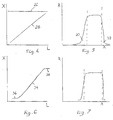
- Fig. 4 illustrates schematically the periodicity of the grating filter 10 along the length L of the filter.
- the upper, horizontal line 26 is representative of the initial period X of the grating when no mechanical nor thermal action is exerted on the filter 10 of Fig. 1 or Fig. 2.
- This gradient in the period is the result of two factors - the graded heating of the filter 10 and the co-acting graded tensile stress imparted onto the filter 10 by the graded expansion of the aluminum block 14 to which the fiber 10 is continuously secured. While the fiber will also expand (in a graded manner) under the graded heating, the block 14 will expand to a severalfold greater degree. Thus, the thermal expansion of the fiber becomes virtually meaningless, while the stretching imparted by the expansion of the block 14 will co-act with the influence of the graded heating on the period of the filter 10.
- the graph of Fig. 3 corresponds to the horizontal line of Fig. 4, representing the initial uniform periodicity of the grating of the filter 10.
- Fig. 5 illustrates graphically the optical response of the fiber 10 due to the operation of the device of the invention (and the use of the method of the invention). It will be seen that the initial bandwidth 24 (Fig. 3) has broadened considerably and has also shifted to a degree controlled by the temperature gradient between the ends of the filter 10.
- the operation of the device of invention is of course reversible.
- the graph of Fig. 5 will return to the shape of Fig. 3 when the effect of temperature onto the block 14 and the fiber 10 is withdrawn by the return of the temperature to the initial level.
- a Peltier type heater/cooler (not shown in the drawing) can be employed in association with the device of Fig. 1 or Fig. 2.
- the Peltier device incorporates the temperature-maintaining means discussed hereinabove.
- the band In the optical communication field, it is usually desired that the band fully "fills” a desired wavelength channel wherein the reflectivity profile of the band assumes a "top hat", or rectangular shape.
- This is advantageous for a variety of reasons.
- the graph of Fig. 5 still has side lobes 30, 32 on either side of the main band which is defined by the two vertical dashed lines.
- the lobes may pose a crosstalk problem and are usually deleterious and unwanted.
- the invention incorporates means for at least reducing the lobes by modifying the reflectivity response of the filter to approximate the ideal, rectangular shape as defined by the dashed lines of Fig. 5.
- the device as illustrated in Fig. 2 is representative of this concept.
- the optical response of the filter so tuned is represented in Fig. 7.
- the reflectivity profile (R versus ⁇ ) is more rectangular-shaped, or has smaller lobes, than the profile of Fig. 5.
- An alternative to the device of Figs. 1 and 2 is to attach the filter 10 to the conductive substrate in a manner approximating a continuous affixment, e.g. by clamping or fixing the fiber to the conductive substrate at several spots
- the substrate may have any regular or irregular shape as dictated by the desired heat transfer pattern.
- the gratings shown are preferably impressed within an optical fibre, other optical waveguide structures can conveniently be utilized; for example a plurality of gratings can be written into a slab waveguide wherein heating elements can be used to control the wavelength reflectivity response of the gratings.
- Other embodiments may be envisaged.
- the device and method of this invention may be used for filtering, demultiplexing and dispersion compensation tuning of optical signals.
Landscapes
- Physics & Mathematics (AREA)
- General Physics & Mathematics (AREA)
- Optics & Photonics (AREA)
- Nonlinear Science (AREA)
- Diffracting Gratings Or Hologram Optical Elements (AREA)
- Light Guides In General And Applications Therefor (AREA)
- Optical Fibers, Optical Fiber Cores, And Optical Fiber Bundles (AREA)
- Mechanical Light Control Or Optical Switches (AREA)
Applications Claiming Priority (2)
| Application Number | Priority Date | Filing Date | Title |
|---|---|---|---|
| US82475397A | 1997-03-26 | 1997-03-26 | |
| US824753 | 1997-03-26 |
Publications (2)
| Publication Number | Publication Date |
|---|---|
| EP0867736A2 true EP0867736A2 (de) | 1998-09-30 |
| EP0867736A3 EP0867736A3 (de) | 1999-08-18 |
Family
ID=25242228
Family Applications (1)
| Application Number | Title | Priority Date | Filing Date |
|---|---|---|---|
| EP98105350A Withdrawn EP0867736A3 (de) | 1997-03-26 | 1998-03-24 | Verfahren und Vorrichtung zur Abstimmung der Wellenlänge und der Bandbreite eines optischen Gitters |
Country Status (3)
| Country | Link |
|---|---|
| EP (1) | EP0867736A3 (de) |
| JP (1) | JPH10325928A (de) |
| CA (1) | CA2229958A1 (de) |
Cited By (15)
| Publication number | Priority date | Publication date | Assignee | Title |
|---|---|---|---|---|
| EP1024391A1 (de) * | 1999-01-26 | 2000-08-02 | Lucent Technologies Inc. | Verfahren zur Herstellung von optischen gechirpten Gitter mit einem intrinsisch gechirpten Gitter und externem Gradienten |
| EP1026540A1 (de) * | 1999-02-02 | 2000-08-09 | Lucent Technologies Inc. | Thermisch regelbares faseroptisches Gitterelement mit Gehäuse für verbesserte Leistungsmerkmale |
| US6411746B1 (en) | 2000-01-18 | 2002-06-25 | Corning Incorporated | Thermally tunable optical devices |
| JP2002533743A (ja) * | 1998-12-04 | 2002-10-08 | シドラ コーポレイション | 管に収容されたブラッグ回折格子を形成する方法および装置 |
| EP1271199A1 (de) * | 2001-06-28 | 2003-01-02 | Corning O.T.I. S.p.A. | Optische Einrichtung zur Kompensation der chromatischen Dispersion |
| US6525870B1 (en) * | 2001-07-26 | 2003-02-25 | Ciena Corporation | Method and system for controlling Raman gain flatness sensitivity to pump laser wavelength variation |
| US6527441B1 (en) * | 1998-06-18 | 2003-03-04 | Qinetiq Limited | Temperature sensing apparatus |
| US6556726B2 (en) | 2000-08-07 | 2003-04-29 | Industrial Technology Research Institute | Electric optical fiber grating filter with switchable central wavelength |
| US6842567B2 (en) | 2002-02-07 | 2005-01-11 | Teraxion Inc. | Power efficient assemblies for applying a temperature gradient to a refractive index grating |
| US6937793B2 (en) | 2002-07-26 | 2005-08-30 | Teraxion Inc. | Tunable chromatic dispersion compensator |
| US6941044B2 (en) | 2001-07-25 | 2005-09-06 | Teraxion Inc. | Tunable optical structure for the compensation of chromatic dispersion in a light signal |
| US8331745B2 (en) | 2009-03-18 | 2012-12-11 | Teraxion Inc. | Assembly for applying a temperature gradient to a refractive index grating and chromatic dispersion compensator |
| CN103308977A (zh) * | 2013-06-08 | 2013-09-18 | 北京品傲光电科技有限公司 | 一种带宽可控的光纤光栅刻写方法及装置 |
| WO2023139024A1 (en) * | 2022-01-18 | 2023-07-27 | Nkt Photonics A/S | Wavelength-stabilised narrow-linewidth mode-locked picosecond laser system |
| CN117310868A (zh) * | 2023-09-26 | 2023-12-29 | 浙江贝良风能电子科技有限公司 | 一种光纤光栅拉伸设备及其使用方法 |
Families Citing this family (1)
| Publication number | Priority date | Publication date | Assignee | Title |
|---|---|---|---|---|
| CN112068238A (zh) * | 2020-09-07 | 2020-12-11 | 桂林电子科技大学 | 一种单应力元光纤啁啾光纤布拉格光栅及其制备方法 |
Family Cites Families (2)
| Publication number | Priority date | Publication date | Assignee | Title |
|---|---|---|---|---|
| US5042898A (en) * | 1989-12-26 | 1991-08-27 | United Technologies Corporation | Incorporated Bragg filter temperature compensated optical waveguide device |
| AUPM547194A0 (en) * | 1994-05-06 | 1994-06-02 | University Of Sydney, The | Variable property light transmitting device |
-
1998
- 1998-02-20 CA CA 2229958 patent/CA2229958A1/en not_active Abandoned
- 1998-03-24 EP EP98105350A patent/EP0867736A3/de not_active Withdrawn
- 1998-03-25 JP JP10096745A patent/JPH10325928A/ja active Pending
Cited By (16)
| Publication number | Priority date | Publication date | Assignee | Title |
|---|---|---|---|---|
| US6527441B1 (en) * | 1998-06-18 | 2003-03-04 | Qinetiq Limited | Temperature sensing apparatus |
| US6351585B1 (en) | 1998-10-30 | 2002-02-26 | Lucent Technologies Inc. | Thermally adjustable optical fiber grating device with packaging for enhanced performance |
| JP2002533743A (ja) * | 1998-12-04 | 2002-10-08 | シドラ コーポレイション | 管に収容されたブラッグ回折格子を形成する方法および装置 |
| EP1024391A1 (de) * | 1999-01-26 | 2000-08-02 | Lucent Technologies Inc. | Verfahren zur Herstellung von optischen gechirpten Gitter mit einem intrinsisch gechirpten Gitter und externem Gradienten |
| EP1026540A1 (de) * | 1999-02-02 | 2000-08-09 | Lucent Technologies Inc. | Thermisch regelbares faseroptisches Gitterelement mit Gehäuse für verbesserte Leistungsmerkmale |
| US6411746B1 (en) | 2000-01-18 | 2002-06-25 | Corning Incorporated | Thermally tunable optical devices |
| US6556726B2 (en) | 2000-08-07 | 2003-04-29 | Industrial Technology Research Institute | Electric optical fiber grating filter with switchable central wavelength |
| EP1271199A1 (de) * | 2001-06-28 | 2003-01-02 | Corning O.T.I. S.p.A. | Optische Einrichtung zur Kompensation der chromatischen Dispersion |
| US6941044B2 (en) | 2001-07-25 | 2005-09-06 | Teraxion Inc. | Tunable optical structure for the compensation of chromatic dispersion in a light signal |
| US6525870B1 (en) * | 2001-07-26 | 2003-02-25 | Ciena Corporation | Method and system for controlling Raman gain flatness sensitivity to pump laser wavelength variation |
| US6842567B2 (en) | 2002-02-07 | 2005-01-11 | Teraxion Inc. | Power efficient assemblies for applying a temperature gradient to a refractive index grating |
| US6937793B2 (en) | 2002-07-26 | 2005-08-30 | Teraxion Inc. | Tunable chromatic dispersion compensator |
| US8331745B2 (en) | 2009-03-18 | 2012-12-11 | Teraxion Inc. | Assembly for applying a temperature gradient to a refractive index grating and chromatic dispersion compensator |
| CN103308977A (zh) * | 2013-06-08 | 2013-09-18 | 北京品傲光电科技有限公司 | 一种带宽可控的光纤光栅刻写方法及装置 |
| WO2023139024A1 (en) * | 2022-01-18 | 2023-07-27 | Nkt Photonics A/S | Wavelength-stabilised narrow-linewidth mode-locked picosecond laser system |
| CN117310868A (zh) * | 2023-09-26 | 2023-12-29 | 浙江贝良风能电子科技有限公司 | 一种光纤光栅拉伸设备及其使用方法 |
Also Published As
| Publication number | Publication date |
|---|---|
| EP0867736A3 (de) | 1999-08-18 |
| CA2229958A1 (en) | 1998-09-26 |
| JPH10325928A (ja) | 1998-12-08 |
Similar Documents
| Publication | Publication Date | Title |
|---|---|---|
| US5694501A (en) | Apparatus and method of bragg intra-grating strain control | |
| EP0867736A2 (de) | Verfahren und Vorrichtung zur Abstimmung der Wellenlänge und der Bandbreite eines optischen Gitters | |
| US6937793B2 (en) | Tunable chromatic dispersion compensator | |
| US6256428B1 (en) | Cascading of tunable optical filter elements | |
| US5699468A (en) | Bragg grating variable optical attenuator | |
| EP1008875B1 (de) | Verfahren zur Ätzung einer optischen Faser | |
| US20030053783A1 (en) | Optical fiber having temperature independent optical characteristics | |
| EP1024376A1 (de) | Optische Gittervorrichtung mit variabler Beschichtung | |
| US6240220B1 (en) | Tunable optical fiber package | |
| JPH10505920A (ja) | 圧縮により波長可変としたファイバグレーティング | |
| EP1055143B1 (de) | Hintereinanderschaltung von abstimmbaren optischen filterelementen | |
| US6879755B2 (en) | Optical structure for the compensation of chromatic dispersion and dispersion slope in a light signal | |
| US9864131B2 (en) | Tunable superstructure fiber grating device | |
| US7050676B2 (en) | Optical signal encoding apparatus and decoding apparatus | |
| US7711224B1 (en) | Colorless multichannel tunable dispersion compensator | |
| US6792009B2 (en) | Tunable grating-based channel filter parking device | |
| US6633702B2 (en) | Device for adjustable chirping in-fiber Bragg gratings and method for producing same | |
| US6941044B2 (en) | Tunable optical structure for the compensation of chromatic dispersion in a light signal | |
| WO1997031289A1 (en) | Apparatus and method for controlling the spectral response of a waveguide bragg grating | |
| US20030227097A1 (en) | Method of fabricating a polymer part with a negative thermal expansion coefficient and a polymer part obtained by the method | |
| EP1345054A1 (de) | Durchlassfilter basierend auf abstimmbarem Glasfasergitter | |
| EP1243949A1 (de) | Optische Filtervorrichtung, Verfahren zur Abstimmung und Kommunikationssystem | |
| Zou et al. | Polymer Bragg gratings for telecom applications | |
| US20030026543A1 (en) | Tunable wideband dispersion compensator | |
| JP2002055245A (ja) | 可変チャープグレーティング光ファイバ装置及びその製造方法 |
Legal Events
| Date | Code | Title | Description |
|---|---|---|---|
| PUAI | Public reference made under article 153(3) epc to a published international application that has entered the european phase |
Free format text: ORIGINAL CODE: 0009012 |
|
| AK | Designated contracting states |
Kind code of ref document: A2 Designated state(s): AT BE CH DE DK ES FI FR GB GR IE IT LI LU MC NL PT SE |
|
| AX | Request for extension of the european patent |
Free format text: AL;LT;LV;MK;RO;SI |
|
| PUAL | Search report despatched |
Free format text: ORIGINAL CODE: 0009013 |
|
| AK | Designated contracting states |
Kind code of ref document: A3 Designated state(s): AT BE CH DE DK ES FI FR GB GR IE IT LI LU MC NL PT SE |
|
| AX | Request for extension of the european patent |
Free format text: AL;LT;LV;MK;RO;SI |
|
| RIC1 | Information provided on ipc code assigned before grant |
Free format text: 6G 02B 6/16 A, 6G 02B 6/34 B, 6G 02B 6/124 B |
|
| AKX | Designation fees paid | ||
| REG | Reference to a national code |
Ref country code: DE Ref legal event code: 8566 |
|
| STAA | Information on the status of an ep patent application or granted ep patent |
Free format text: STATUS: THE APPLICATION IS DEEMED TO BE WITHDRAWN |
|
| 18D | Application deemed to be withdrawn |
Effective date: 20000219 |