EP0867738A2 - Terminaison pour fibres optiques - Google Patents
Terminaison pour fibres optiques Download PDFInfo
- Publication number
- EP0867738A2 EP0867738A2 EP98302272A EP98302272A EP0867738A2 EP 0867738 A2 EP0867738 A2 EP 0867738A2 EP 98302272 A EP98302272 A EP 98302272A EP 98302272 A EP98302272 A EP 98302272A EP 0867738 A2 EP0867738 A2 EP 0867738A2
- Authority
- EP
- European Patent Office
- Prior art keywords
- receipt
- space
- transmission member
- optical transmission
- substrate
- Prior art date
- Legal status (The legal status is an assumption and is not a legal conclusion. Google has not performed a legal analysis and makes no representation as to the accuracy of the status listed.)
- Withdrawn
Links
Images


Classifications
-
- G—PHYSICS
- G02—OPTICS
- G02B—OPTICAL ELEMENTS, SYSTEMS OR APPARATUS
- G02B6/00—Light guides; Structural details of arrangements comprising light guides and other optical elements, e.g. couplings
- G02B6/24—Coupling light guides
- G02B6/36—Mechanical coupling means
- G02B6/38—Mechanical coupling means having fibre to fibre mating means
- G02B6/3807—Dismountable connectors, i.e. comprising plugs
- G02B6/3833—Details of mounting fibres in ferrules; Assembly methods; Manufacture
- G02B6/3855—Details of mounting fibres in ferrules; Assembly methods; Manufacture characterised by the method of anchoring or fixing the fibre within the ferrule
- G02B6/3861—Adhesive bonding
-
- G—PHYSICS
- G02—OPTICS
- G02B—OPTICAL ELEMENTS, SYSTEMS OR APPARATUS
- G02B6/00—Light guides; Structural details of arrangements comprising light guides and other optical elements, e.g. couplings
- G02B6/24—Coupling light guides
- G02B6/36—Mechanical coupling means
- G02B6/38—Mechanical coupling means having fibre to fibre mating means
- G02B6/3807—Dismountable connectors, i.e. comprising plugs
- G02B6/3833—Details of mounting fibres in ferrules; Assembly methods; Manufacture
- G02B6/3834—Means for centering or aligning the light guide within the ferrule
- G02B6/3838—Means for centering or aligning the light guide within the ferrule using grooves for light guides
-
- G—PHYSICS
- G02—OPTICS
- G02B—OPTICAL ELEMENTS, SYSTEMS OR APPARATUS
- G02B6/00—Light guides; Structural details of arrangements comprising light guides and other optical elements, e.g. couplings
- G02B6/24—Coupling light guides
- G02B6/36—Mechanical coupling means
- G02B6/38—Mechanical coupling means having fibre to fibre mating means
- G02B6/3807—Dismountable connectors, i.e. comprising plugs
- G02B6/3833—Details of mounting fibres in ferrules; Assembly methods; Manufacture
- G02B6/3834—Means for centering or aligning the light guide within the ferrule
- G02B6/3838—Means for centering or aligning the light guide within the ferrule using grooves for light guides
- G02B6/3839—Means for centering or aligning the light guide within the ferrule using grooves for light guides for a plurality of light guides
Definitions
- the present invention relates to an improvement on optical transmission member-fixed assembly comprising a substrate and a lid integrated with the substrate, the substrate being provided with a receipt groove for receiving a core wire of an optical fiber and a receipt seat for receiving at least a covering of the optical.
- Various types of substrates are known to fix optical fibers having diameters of for example around 125 ⁇ m.
- a light transmission loss between the optical fiber and another optical transmission means becomes greater. Therefore, an extremely high working precision such as 0.5 ⁇ m or less is required as a working precision in a fixing groove of the optical fiber-fixing substrate.
- grooves each having a V-shaped section are formed in the substrate, each optical fiber is placed in the corresponding groove, and each optical fiber is fixed there with a resin or solder.
- Fig. 1(a) is a front view for schematically illustrating an example of an optical fiber-fixed assembly with such an optical fiber-fixing substrate
- Figs. 1(b) and 1(c) are a plane view and a left side view for also schematically illustrating this assembly, respectively.
- the optical fiber-fixed assembly 1 includes a fixing substrate 3 and lids 2 and 4.
- the fixing substrate 3 includes a receipt seat 3c for receiving coverings of optical fibers, and the coverings 5 are received in the receipt seat 3c.
- a lid 2 is placed on the coverings 5.
- a holding portion 3a of the fixing substrate 3 is provided with given rows of receipt grooves 9. Each groove 9 extends from an end face 7 toward a stepped portion 3b.
- a core wire 8 of the optical fiber is placed in each groove 9, and fixed there with an adhesive such as a resin.
- the lid 4 is placed on the holding portion 3a.
- an optical fiber-fixing substrate is prepared from ceramic or glass.
- Each receipt groove 9 is as very thin as for example one hundred and dozens ⁇ m.
- the present inventors discovered that the above optical fiber-fixed assembly might suffer from the following problems. That is, the fixed assembly is desired to suppress the insertion loss of the light to a given area over a wide temperature range.
- the optical fiber-fixed assembly is often arranged in a very low temperature environment.
- the optical fiber-fixed assembly may reach near a temperature of 85°C even in the shade depending upon a placing location.
- the operational temperature environment of optical parts mounted in automobiles is classified into the following three cases. That is, if the optical part is mounted in a trunk room, the optical part needs to withstand temperature changes in a range of -20°C to +60°C. If it is mounted in a vehicle compartment into which sun light does not directly hit, it needs withstand temperature changes in a range of -40°C to +85°C. If the optical part is mounted in an engine room, it needs withstand temperature changes in a range of -40°C to +120°C.
- the present inventors produced optical-fiber fixed assemblies each having a configuration as shown in Figs. 1(a) to 1(c), placed each of them in a given package and then subjected the package to a heat impact test and a heat cycle test over a wide temperature range of for example -40°C to +85°C.
- a heat impact test and a heat cycle test over a wide temperature range of for example -40°C to +85°C.
- the present invention is to prevent deterioration of light transmission characteristics such as the light insertion loss even under application of heat impacts or heat cycles over a wide temperature range with respect to the optical transmission member-fixed assembly which includes a substrate with a receipt groove for receiving a core wire of the optical transmission member and a lid integrated with the substrate, while a receipt space is provided between the substrate and the lid for receiving at least covering of the optical transmission member.
- the present invention relates to an optical transmission member-fixed assembly which comprises a substrate with a receipt groove in which a core wire of an optical transmission member is received, a lid integrated with the substrate, while between the substrate and the lid is provided a receipt space in which at least a covering of the optical transmission member is received, a dimension of the receipt space being greater than that of the receipt groove when as viewed in a vertical direction to the optical transmission member, wherein an adhesive is filled around the core wire inside the receipt groove for fixing the core wire there, an adhesive is filled around the optical transmission member within the receipt space for fixing the optical transmission member there, a boundary space zone is provided between the receipt space and the receipt groove, a thickness of the adhesive filled around the optical transmission member inside the boundary space is continuously reduced as a location of the boundary space zone is at least near and goes to an opening of the receipt groove at an end opposed to the receipt space.
- the present inventors produced optical fiber-fixed assemblies as shown in for example Figs. 1(a) to 1(c), placed and sealed each of them in a given package, and subjected such packages to the heat impact test and the heat cycle test. At that time, defective products having the light insertion loss conspicuously reduced in some cases.
- the present inventors investigated this phenomenon according to the following process, elucidated the cause therefor, and reached the present invention based on this elucidation.
- the present inventors first noted differences in dimensional changes between the packages and the optical fiber-fixed assemblies when the temperature changed. Since the optical fibers are fixed to both the package and the optical fiber-fixed assembly, it was thought that the package moved relative to the optical fiber-fixed assembly in compliance with changes in temperature, and consequently tensile stress was applied to the optical fiber.
- the present inventors conducted an experiment in which optical fibers were pulled out from optical fiber-fixed assemblies. As a result, it turned out that pulling force of about 0.49 kgf was required to pull out each optical fiber. Further, the inventors conducted an experiment in which after the optical fibers were sealingly fixed to the package, the optical fibers were pulled out from the package. Consequently, pulling force of about 0.116 kgf was required for each optical fiber. As is seen from the above, since the pulling force required to pull out the optical fiber from the optical fiber-fixed assembly was far greater than that required to pull out the optical fiber from the package, it is highly possible that the optical fiber is broken inside the optical fiber-fixed assembly by such pulling force.
- optical fibers were actually assembled in an optical fiber-fixing assembly, pulling force was applied to the optical fibers and behavior of the optical fibers were measured.
- Fourteen optical fiber-fixed assemblies were subjected to the experiment. As a result, the optical fibers were broken at boundary between the receipt groove 9 and the receipt seat 3c in two assemblies, and the optical fibers were broken inside the receipt groove 9 in nine assemblies, whereas the optical fibers were pulled out from three fixing assemblies.
- the defective optical-fixed fixed assemblies after the heat impact test or the heat cycle test were dissembled, and the state of broken faces at broken locations of the optical fibers was observed.
- the broken face exhibited almost the state shown in Fig. 2.
- fresh optical fibers were actually broken by applying tensile stress or bending stress to them, their broken faces were observed, and compared with those of the optical fibers of the actual assemblies.
- states 10a, 10b and 10c are different states 10a, 10b and 10c.
- These states of the broken face can be analyzed as follows. That is, when bending stress is applied to the optical fiber, tensile stress is concentrated locally at a portion of the optical fiber at a peripheral edge, the optical fiber begins to be broken at 10a as a breakage-stating point by the tensile stress. Such breakage relatively slowly proceeds from the starting point 10a to form an initial-stage broken face 10b. When the breakage proceeds to some extent, such breakage rapidly proceeds in the lower side of the optical fiber in Fig. 2. Thus, a broken face 10c different from the initial-stage one 10b is formed.
- a portion 10d corresponds to just a contact between the optical fiber and an optical fiber-receiving groove (in this experiment, so-called V-shaped grooves were employed), and breakage speedily proceeds near the contact, thereby forming the rapidly breakage-proceeded face 10d.
- Fig. 3 is a sectional view of illustrating near the boundary between the receipt groove 9 and the receipt seat 3c in the optical fiber-fixed assembly before the heat impact test or the heat cycle test in an enlarged scale.
- an adhesive layer 20 is provided between the outer peripheral surface of a core wire of the optical fiber an the bottom face 3d of the receipt groove 9 and between the outer peripheral surface of the core wire 8 and a wall surface 4a of the lid 4 so that the core wire 8 may be surrounded by the adhesive layer.
- the core wire 8 extends to a side of the receipt seat 3c through an outlet 9a of the receipt groove 9.
- the lid 2 is provided with a rectangular parallelopiped receiving seat 35 for receiving at least a covering of the optical fiber.
- a receipt space 38 is defined by the receipt seats 3c and 35.
- the adhesive layer 12 is bonded to wall faces of the substrate 3 and the wall 2a of the lid 2.
- the cause for the breakage of the optical fiber is considered as follows. That is, it is considered that as the temperature lowers, the adhesive shrinks around and toward the optical fiber as shown by arrows C and D, and that since the resin is not uniform at every portion in terms of density, etc., the adhesive is non-uniformly shrunk around the optical fiber. It is further considered that when a part of the outer peripheral portion of the adhesive layer 12 peels from the lid 2 or the substrate 3, bending stress is rapidly applied to this peeled part of the adhesive as shown by an arrow B. The core wire 8 is likely to be cut by this bending stress.
- the present inventors assembled optical fiber-fixed assemblies by using an epoxy resin adhesive or acrylic resin UV-curable type resin adhesive as an adhesive, and subjected them to the heat impact test or the heat cycle test.
- the elastic modulus and the coefficient of thermal expansion of the epoxy resin adhesive were 35 kg/cm 2 and 1.8 x 10 -4 /°C, respectively.
- the elastic modulus and the coefficient of thermal expansion of the acrylic UV-curable type resin adhesive were 3900 kg/cm 2 and 0.8 x 10 -4 /°C, respectively.
- the coefficient of thermal expansion of the epoxy resin adhesive is greater than that of the acrylic one and therefore displacement of the former is not less than 2 times that of the latter when the temperature changes, it can be presumed that the number of defective assemblies is greater in the case of the epoxy resin adhesive.
- the occurrence percentage of defective assemblies was far higher with a lower yield in the use of the acrylic UV-curable resin adhesive than in the use of the epoxy resin adhesive. The reason is that since the acrylic UV-curable type resin adhesive has a lower elastic modulus, it is likely to peel from the wall surface of the lid and its stress is larger, even if the displacement is small.
- JP-A-8 286078 proposes that a core wire-holding portion is provided higher than an optical fiber-placing portion, a corner portion of a step due to a difference in height is designed to have a curvature or an obtuse angle.
- the present inventors produced optical transmission member-fixed assemblies having such a structure, it turned out that their light transmission characteristic degraded against severe heat impact and heat cycles applied over the above-mentioned wide temperature range.
- the present inventors found it most important to continuously decrease the thickness of the adhesive around the optical transmission member in the boundary zone between the receipt space and the receipt grooves at least near openings of the receipt grooves as the location of the receipt space goes toward the receipt grooves.
- the inventors reached the present invention based on this finding.
- the thickness of the adhesive around the optical transmission member inside the boundary zone at a constant volume-decreasing rate as the location of the boundary zone goes to near the openings at the ends of the receipt grooves.
- Fig. 5 is a perspective view for illustrating an embodiment of thus constructed optical fiber-fixed assembly according to the present invention in a dissembled state.
- Fig. 6 is a sectional view of illustrating a boundary zone between a receipt groove 9 and a receipt seat 17 in the assembly of Fig. 5 in an enlarged scale.
- a lid 15, an optical fiber 31 composed of a covering 16 and a core wire 8 and a substrate 17 are assembled together, while a surface 17a of the substrate 17 is opposed to the lid 15.
- An adhesive layer 20 is provided inside the receipt groove 9 between the outer peripheral surface of the core wire 8 of the optical fiber and a bottom surface 17d of the receipt groove 9 and between the outer peripheral surface of the core wire 8 and a wall surface 15c of the lid 15 such that the adhesive layer may surround the core wire.
- the core wire 8 extends into a side of the receipt space 17b through an end 9a of the receipt groove 9.
- An adhesive layer 22 is provided between the wall surface 17 of the receipt space 17b and the core wire, and the adhesive layer 22 is bonded to the wall surface 17c.
- an adhesive layer is filled between the side wall surface 17e of the receipt seat and the optical fiber 31.
- the lid 15 is provided with a receipt seat 36 for receiving at least the covering of the optical fiber.
- An adhesive layer 21 is provided between the wall surface 15a of the lid 15, and is bonded to the wall surface 15a.
- a receipt space 39 is defined by the receipt seat 17b and the receipt seat 36 of the lid.
- an almost flat inclined surface 18 is provided in a boundary zone 27 between the receipt space 39 and the receipt groove 9 in a boundary zone 27 between the receipt space 39 and the receipt groove 9 in a boundary zone 27 between the receipt space 39 and the receipt groove 9 in a boundary zone 27 between the receipt space 39 and the receipt groove 9 in a boundary zone 27 between the receipt space 39 and the receipt groove 9 in a boundary zone 27 between the receipt space 39 and the receipt groove 9 in a boundary zone 27 between the receipt space 39 and the receipt groove 9 is provided an almost flat inclined surface 18 at a location from near the end opening 9a of the receipt groove 9 to the receipt seat 17b.
- the adhesive layer 22 is also bonded to the inclined surface 18.
- the lid 15 is provided with an almost flat inclined surface 15b extending from the end opening 9a of the receipt groove 9 to the receipt space 39, and the adhesive layer 21 is bonded to the inclined surface 15b.
- the thickness of the adhesive layer 21 and that of the adhesive layer 22 continuously decrease as the location goes from the receipt space 39 toward the end opening 9a of the receipt groove 9.
- the adhesive is shrunk around and toward the optical fiber as shown by arrows E and F as the temperature lowers.
- the thicknesses of the adhesive layers 21 and 22 first continuously decrease in the boundary zone 27, so that the shrunk amounts of the adhesive in the directions E and F gradually decrease as the location approaches the receipt groove 9. For this reason, the nearer to the receipt groove 9 the location, the more difficult for the adhesive layers 21, 22 to peel from the substrate and the lid.
- the adhesive layers 21, 22 are likely to peel from the wall surfaces 15a and the 17c, that is, the adhesive layers are more likely to peel in an area outside the boundary zone 27.
- bending stress of the adhesive layer through deformation thereof is not so applied to near the opening 9a of the receipt groove, but dispersed over the entire length of the boundary zone 27.
- the optical fiber is unlikely to be cut.
- the thicknesses of the adhesive layers 21, 22 particularly near the end opening 9a of the receipt groove 9 is continuously decreased, whereas the adhesive layer at a side of the end of the adhesive layer contributes to a smaller extent.
- the term "near the opening 9a" means an area falling within 1 mm from the opening 9a.
- ratios p/q and m/n at not less than 0.70 in which p and m are sizes of the inclined surfaces 15b and 18 as viewed in a longitudinal direction of the optical fiber, respectively, wherein q and n are sizes of the inclined surfaces 15b and 18, respectively, as viewed in a vertical direction to the optical fiber.
- q/p + n/m means a volume-decreased rate.
- p/q and m/n are preferably not more than 11.5, because the dimension of the receipt space 39 as viewed in the longitudinal direction of the optical fiber can be prevented from being excessive.
- each of the inclined surfaces 15 and 18 are almost flat, they can be easily formed by working or the like.
- each of the inclined surfaces need not be flat, and may be of an arbitrary curved shape or of a stepwise shape, so long as the thickness of the adhesive around the optical transmission member within the receipt space 39 can be continuously decreased as the location of the boundary zone goes from the receipt space 39 toward the receipt groove 9.
- a reference surface for arraying the covering of the optical transmission member near the end of the receipt space.
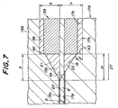
- Fig. 7 is a sectional view of a principal portion of another embodiment of the optical transmission member-fixed assembly according to the present invention.
- the same parts as in Fig. 6 are given the same reference numerals, and their explanation is omitted.
- a reference surface 43 having a height "z" is formed between an end side of an inclined surface 18 of a substrate 17A and a receipt seat 17b.
- the lid 15A is provided with a vertical surface 42 between the end of the receipt seat 15a and an inclined surface 15b, and the covering can be located by the vertical surface 42.
- the optical transmission member is preferably the optical fiber, but the optical transmission member may be a passive optical transmission member such as a rod lens.
- the contour of the receipt groove formed in the optical fiber-fixing substrate is preferably a so called V-shape, but grooves having other sectional shapes may be employed.
- a receipt groove may be formed in a substrate made of a silicon material by etching the substrate.
- the receipt groove may be formed by grinding a substrate made of a ceramic material such as alumina, agate or zirconia or a glass material.
- the receipt groove is formed by preparing a sintered body through sintering a ceramic molded body, forming a flat surface by plane grinding the sintered body, and then grinding the flat surface with diamond.
- the receipt groove may be formed by press molding.
- a constant “c” is preferably not less than 1.2, this constant “c” being a constant in the following formula which represents a volume-reduced rate of the thickness of the adhesive around the optical transmission member within the boundary zone.
- volume-reducing percentage (%) (-log (a ⁇ b) ⁇ 100)) ⁇ 100/c a: elastic modulus (kg/mm 2 ), b: coefficient of thermal expansion of adhesive (°C)
- the constant "c" is preferably not more than 10 in order to make the dimension of the optical transmission member-fixed assembly in a practical range.
- An optical fiber-fixed assembly having the structure shown in Fig. 3 and an optical fiber-fixed assembly having the invention structure shown in Fig. 6 were produced.
- Substrates 3, 17 each having a dimension of 5.0 mm x 2.5 mm x 2.0 mm and lids 2, 15 having a dimension of 4.5 mm x 1.5 mm x 1.0 mm were repaired from optical glass.
- a single groove 9 was formed in each substrate by a slicing machine.
- a receipt seat 3c having a rectangular parallelepiped shape was formed in the structure as comparative example by ultrasonic wave working.
- This receipt seat 3c had a dimension of 2 mm length x 0.8 width x 0.25 mm depth.
- a receipt seat 35 was formed by ultrasonically working the lid 2.
- the receipt seat 35 had a dimension of 1.5 mm length x 0.8 width x 0.15 mm depth.
- a receipt seat 17b having a rectangular parallelepiped shape was formed by ultrasonic wave working.
- This receipt seat 17b had a dimension of 2 mm length x 0.8 width x 0.25 mm depth.
- a receipt seat 36 was formed by ultrasonically working the lid 15.
- the receipt seat 36 had a dimension of 1.66 mm length x 0.8 width x 0.15 mm depth.
- m was 0.43 mm, n 0.25 mm, p 0.24 mm and q 0.15 mm.
- a polarized face-holding optical fiber having an outer clad diameter of 80 ⁇ m was used as an optical fiber.
- An epoxy resin adhesive was used as an adhesive.
- Each of the fixed assemblies of the invention example and the comparative example was subjected to a heat cycle test. More specifically, the assembly was heated from room temperature to 85°C at a rate of 25°C/min., held at 85°C for one hour, cooled down to -40°C at a rate of 25°C/min., and held at -40°C for one hour. This cycle was repeated at 450 times.
- Optical transmission member-fixed assemblies each having the structure shown in Fig. 6 were produced in the same manner as in Experiment 1.
- Resins used were A or B shown in Table 1.
- Kind of resin Elastic modulus kg/mm 2 Coefficient of heat expansion/°C
- Epoxy resin 0.35 1.6 ⁇ 10 -4
- Acrylic resin 39 0.8 ⁇ 10 -4
- the constant "c” is extremely important in relation to the coefficient of thermal expansion and the elastic modulus of the resin used. Particularly, if the temperature change is -20°C to +60°C, setting of "c” at not less than 1.2 is extremely effective. Further, if the temperature change is -40°C to +85°C, setting of "c” at not less than 2.0 is extremely effective. Furthermore, if the temperature change is -40°C to +120°C, setting of "c" at not less than 2.5 is extremely effective.
- the present invention it is possible to prevent the degradation of the light transmission characteristic such as the light insertion loss even under application of heat impact or heat cycles over a wide temperature range.
Landscapes
- Physics & Mathematics (AREA)
- General Physics & Mathematics (AREA)
- Optics & Photonics (AREA)
- Mechanical Coupling Of Light Guides (AREA)
Applications Claiming Priority (3)
| Application Number | Priority Date | Filing Date | Title |
|---|---|---|---|
| JP7532297 | 1997-03-27 | ||
| JP75322/97 | 1997-03-27 | ||
| JP7532297 | 1997-03-27 |
Publications (2)
| Publication Number | Publication Date |
|---|---|
| EP0867738A2 true EP0867738A2 (fr) | 1998-09-30 |
| EP0867738A3 EP0867738A3 (fr) | 2000-02-23 |
Family
ID=13572921
Family Applications (1)
| Application Number | Title | Priority Date | Filing Date |
|---|---|---|---|
| EP98302272A Withdrawn EP0867738A3 (fr) | 1997-03-27 | 1998-03-25 | Terminaison pour fibres optiques |
Country Status (2)
| Country | Link |
|---|---|
| US (1) | US6160947A (fr) |
| EP (1) | EP0867738A3 (fr) |
Cited By (2)
| Publication number | Priority date | Publication date | Assignee | Title |
|---|---|---|---|---|
| EP1003057A3 (fr) * | 1998-11-19 | 2002-12-04 | Ngk Insulators, Ltd. | Support de fibre optique |
| EP1139129A3 (fr) * | 2000-03-29 | 2004-03-31 | Ngk Insulators, Ltd. | Réseau de fibres optiques et son procédé de fabrication |
Families Citing this family (8)
| Publication number | Priority date | Publication date | Assignee | Title |
|---|---|---|---|---|
| US6798968B2 (en) * | 2000-09-21 | 2004-09-28 | Shipley Company, L.L.C. | Fiber array with support post |
| KR100442630B1 (ko) * | 2002-01-04 | 2004-08-02 | 삼성전자주식회사 | 광섬유 블럭 |
| JP4080234B2 (ja) * | 2002-05-14 | 2008-04-23 | シャープ株式会社 | 情報処理媒体およびこれを用いた情報処理装置 |
| US6808322B2 (en) * | 2002-09-24 | 2004-10-26 | Triquint Technology Holding Co. | Devices and method of mounting |
| US7085079B2 (en) * | 2002-10-31 | 2006-08-01 | Dainippon Screen Mfg. Co., Ltd. | Optical element module, and apparatus and method for fixing optical element |
| US7794158B2 (en) * | 2007-10-04 | 2010-09-14 | Hitachi Cable Ltd. | Fabrication method of optical interconnection component and optical interconnection component itself |
| CN102096148A (zh) * | 2010-11-19 | 2011-06-15 | 四川天邑康和光电子有限公司 | 光纤阵列及其制造方法 |
| WO2020003124A1 (fr) * | 2018-06-28 | 2020-01-02 | 3M Innovative Properties Company | Élément et ensemble de couplage de lumière |
Family Cites Families (12)
| Publication number | Priority date | Publication date | Assignee | Title |
|---|---|---|---|---|
| US4303304A (en) * | 1979-11-30 | 1981-12-01 | Amp Incorporated | Universal optical waveguide alignment ferrule |
| JPS57118210A (en) * | 1981-01-14 | 1982-07-23 | Nippon Telegr & Teleph Corp <Ntt> | Muilti-core connector of optical fiber |
| CA1302758C (fr) * | 1986-11-15 | 1992-06-09 | Sumitomo Electric Industries, Ltd. | Connecteur optique et methode de fabrication de ce connecteur |
| JP2621048B2 (ja) * | 1988-08-26 | 1997-06-18 | 日本電気硝子株式会社 | 光ファイバ固定具の製造方法 |
| JPH06100696B2 (ja) * | 1988-12-23 | 1994-12-12 | 日本電気株式会社 | 光コネクタフェルール |
| DE3902574A1 (de) * | 1989-01-26 | 1990-08-02 | Siemens Ag | Lichtwellenleiter-verbinder |
| DE4230168C1 (en) * | 1992-09-09 | 1993-08-26 | Siemens Ag, 8000 Muenchen, De | Fixing element for optical-fibre using hardened adhesive - roughens insides surface of insertion opening for gripping fixing adhesive |
| US5351331A (en) * | 1993-09-17 | 1994-09-27 | Motorola, Inc. | Method and apparatus for splicing optical fibers with signal I/O |
| EP1482336A3 (fr) * | 1994-07-21 | 2004-12-22 | Sumitomo Electric Industries, Ltd. | Guide optique comprenant un substrat d'un premier matériau et un embout d'un second matériau |
| JPH08220374A (ja) * | 1995-02-14 | 1996-08-30 | Hitachi Cable Ltd | 光ファイバと光導波路との接続構造 |
| JPH08286078A (ja) * | 1995-04-13 | 1996-11-01 | Kyocera Corp | 光ファイバアレイ |
| JP3620121B2 (ja) * | 1995-10-31 | 2005-02-16 | 住友電気工業株式会社 | 光コネクタ及び組立方法 |
-
1998
- 1998-03-20 US US09/045,744 patent/US6160947A/en not_active Expired - Fee Related
- 1998-03-25 EP EP98302272A patent/EP0867738A3/fr not_active Withdrawn
Cited By (2)
| Publication number | Priority date | Publication date | Assignee | Title |
|---|---|---|---|---|
| EP1003057A3 (fr) * | 1998-11-19 | 2002-12-04 | Ngk Insulators, Ltd. | Support de fibre optique |
| EP1139129A3 (fr) * | 2000-03-29 | 2004-03-31 | Ngk Insulators, Ltd. | Réseau de fibres optiques et son procédé de fabrication |
Also Published As
| Publication number | Publication date |
|---|---|
| EP0867738A3 (fr) | 2000-02-23 |
| US6160947A (en) | 2000-12-12 |
Similar Documents
| Publication | Publication Date | Title |
|---|---|---|
| US6219484B1 (en) | Metal coated optical fiber array module | |
| EP0644442B1 (fr) | Borne de fibre optique, son procede de fabrication, et structure permettant le raccordement de ladite borne a un dispositif optique | |
| EP0867738A2 (fr) | Terminaison pour fibres optiques | |
| EP0860721B1 (fr) | Matrice de fibres optiques et son procédé de fabrication | |
| CA2031059C (fr) | Methode d'assemblage de terminaisons de fibres optiques et de puces de silicium multitranchee | |
| US6939055B2 (en) | Stub having an optical fiber | |
| US6819858B2 (en) | Fiber array with V-groove chip and mount | |
| US6928226B2 (en) | Fiber and lens grippers, optical devices and methods of manufacture | |
| US6416236B1 (en) | Ferrule for facilitating fiber-to-fiber contact and associated fabrication method | |
| US20100183269A1 (en) | Environmentally robust liquid crystal polymer coated optical fiber cable and its use in hermetic packaging | |
| KR20040086477A (ko) | 광섬유 페룰 | |
| JP3821971B2 (ja) | 光ファイバーアレイ | |
| EP1237022A1 (fr) | Emballage hermétique avec traversée de fibre optique | |
| EP0926522A2 (fr) | Embout intégral fusionné thermiquement et son procédé de fabrication, et procédé de fabrication pour une matrice des fibres | |
| EP0850886A1 (fr) | Procédé de fabrication de produits moulés de verre | |
| US6550981B1 (en) | Optical module having an optical coupling between an optical fiber and a laser diode | |
| EP1139131B1 (fr) | Matrice de fibres optiques | |
| CN1275209A (zh) | 具有与外套隔离的光学部件的光学器件 | |
| US6795634B2 (en) | Optical fiber block having holding sub-block | |
| EP1003057A2 (fr) | Support de fibre optique | |
| US6804442B1 (en) | Optical fiber and optical fiber cable having a first jacket layer and a second jacket layer and a coefficient of thermal expansion selecting method | |
| US6324332B1 (en) | Optical fiber fixing member, method of manufacturing the optical fiber fixing member, optical fiber array, and method of manufacturing the optical fiber array | |
| JPS59166903A (ja) | 光フアイバ−アレイ体の製造方法 | |
| US20010021301A1 (en) | Substrate having V-shaped grooves and a manufacturing method therefor, and optical fiber array | |
| US20010024560A1 (en) | Optical fiber array |
Legal Events
| Date | Code | Title | Description |
|---|---|---|---|
| PUAI | Public reference made under article 153(3) epc to a published international application that has entered the european phase |
Free format text: ORIGINAL CODE: 0009012 |
|
| AK | Designated contracting states |
Kind code of ref document: A2 Designated state(s): DE FR GB |
|
| AX | Request for extension of the european patent |
Free format text: AL;LT;LV;MK;RO;SI |
|
| PUAL | Search report despatched |
Free format text: ORIGINAL CODE: 0009013 |
|
| AK | Designated contracting states |
Kind code of ref document: A3 Designated state(s): AT BE CH DE DK ES FI FR GB GR IE IT LI LU MC NL PT SE |
|
| AX | Request for extension of the european patent |
Free format text: AL;LT;LV;MK;RO;SI |
|
| 17P | Request for examination filed |
Effective date: 20000816 |
|
| AKX | Designation fees paid |
Free format text: DE FR GB |
|
| 17Q | First examination report despatched |
Effective date: 20040216 |
|
| STAA | Information on the status of an ep patent application or granted ep patent |
Free format text: STATUS: THE APPLICATION IS DEEMED TO BE WITHDRAWN |
|
| 18D | Application deemed to be withdrawn |
Effective date: 20040629 |