EP0867739A1 - Spule für einen Behälter mit Faseroptik und zugehöriges Herstellungsverfahren - Google Patents
Spule für einen Behälter mit Faseroptik und zugehöriges Herstellungsverfahren Download PDFInfo
- Publication number
- EP0867739A1 EP0867739A1 EP98200876A EP98200876A EP0867739A1 EP 0867739 A1 EP0867739 A1 EP 0867739A1 EP 98200876 A EP98200876 A EP 98200876A EP 98200876 A EP98200876 A EP 98200876A EP 0867739 A1 EP0867739 A1 EP 0867739A1
- Authority
- EP
- European Patent Office
- Prior art keywords
- orthotropic
- bobbin
- filaments
- thermal expansion
- bobbin according
- Prior art date
- Legal status (The legal status is an assumption and is not a legal conclusion. Google has not performed a legal analysis and makes no representation as to the accuracy of the status listed.)
- Withdrawn
Links
Images


Classifications
-
- G—PHYSICS
- G02—OPTICS
- G02B—OPTICAL ELEMENTS, SYSTEMS OR APPARATUS
- G02B6/00—Light guides; Structural details of arrangements comprising light guides and other optical elements, e.g. couplings
- G02B6/44—Mechanical structures for providing tensile strength and external protection for fibres, e.g. optical transmission cables
- G02B6/4439—Auxiliary devices
- G02B6/4457—Bobbins; Reels
Definitions
- the invention relates to bobbins constituting the support of optical fiber canisters, which permit the regular payout of the optical fiber and which maintain the optical fiber pack stable throughout a wide range of temperatures, e.g., from -50°C to +60°C; and to a method for making such bobbins.
- Optical fiber canisters are widely employed in communication applications, e.g., to transnmit information between a flying object, such as a missile, and a launching station, whether fixed or movable. During their use, the optical fibers are paid out from the canisters and this payout must take place regularly without snagging, breakages or other failures.
- Optical fiber canisters are subjected to drastic temperature variations, which may go from several tens of degrees below zero to several tens of degrees above zero, e.g., from -50°C to +60°C. These temperature changes may produce displacements and irregularities in the optical fiber pack, which result in failure during payout of the optical fiber from the canister, or may even produce cracks throughout the optical fiber pack.
- An optical fiber is an orthotropic material, hawing a longitudinal coefficient of terminal expansion which is very nearly zero and a transverse coefficient of terminal expansions which is much larger and may reach and even may exceed 100 ⁇ 10 -6 cm/cm per °C.
- the material of which the bobbin is made may be isotropic or orthotropic.
- Metals, such as aluminum, are of course isotropic and their coefficients of expansion, therefore, cannot match those of the optical fiber in one or the other or both directions.
- this orthotropic material is usually a composite material. constituted with the intent to approach as far as possible in the longitudinal direction the coefficient of expansion of the optical fiber in the transverse direction and to have a very small coefficient of thermal expansion in the radial direction.
- USP 5,205,510 discloses a bobbin which has a sleeve to support the fiber pack, with structural support means inside the sleeve to support it while allowing relative sliding parallel to the long axis of the sleeve.
- the support means has a coefficient of thermal expansion parallel to the long that is much smaller than that of the sleeve.
- USP 5,181,270 discloses a frusto-conical bobbin for supporting an optical fiber pack, which is constructed of material having a coefficient of thermal expansion closely matching that of the optical fiber pack in a direction parallel to the longitudinal axis and which has a slot extending its entire length and completely through its wall. The slot allows the bobbin to expand and contract circumferentially at the same rate as the optical fiber pack expands and contracts in a circumferential direction.
- JP 61201647 discloses a bobbin made of material having a coefficient of thermal expansion which is almost equal to that of the optical fiber to be wound thereupon.
- JP 92053793 B discloses a bobbin of a fiber-reinforced plastic material in which the fibers are distributed to make the thermal expansion ratio in the axial direction lower than that in the circumferential direction.
- USP 4,995,698 discloses an optical fiber canister which comprises a bobbin, on which the optical fiber is wound, which bobbin is made of a composite material formed of a fiber embedded in a matrix, wherein the fiber is preferably an inorganic fiber or Kevlar, and the polymer is an epoxy or phenolic polymer.
- Such bobbins do not approximate closely enough the coefficients of thermal expansion of the fiber in the longitudinal and transverse direction, and particularly do not do so over a temperature range sufficiently broad to cover all the thermal conditions to which optical fiber canisters are commonly subjected.
- the orthotropic bobbin according to the invention is made of a composite material which comprises (I) continuous filaments having a high tensile strength and a low or negative coefficient of thermal expansion and (II) a polymeric matrix having a high coefficient of thermal expansion, wherein said polymeric matrix which is the product of the curing of a matrix precursor composition comprising an epoxy resin, a hardener and a rubber modifier, and, preferably, an accelerator.
- the rubber modifier is carboxyl terminated butadiene-acrylonitrile copolymer (hereinafter sometimes CTBN), available on the market under the trade name Hycar 1300 X13.
- CTBN is a reactive liquid polymer, which, in the thermal curing of said composition, undergoes addition or esterification reactions with the epoxy resin.
- the longitudinal or axial coefficient of thermal expansion (longitudinal or axial CTE) of the composite material of which the bobbin is made, according to the invention, is at least 87 ⁇ 10 -6 cm/cm/°C and may reach 90 ⁇ 10 -6 cm/cm/°C.
- longitudinal or axial CTE is meant the CTE in the direction of the axis of the bobbin.
- the transverse coefficient of expansion of said composite material - viz., the CTE is the direction that is tangential to the bobbin at the point considered, which is also approximately the longitudinal direction of the filaments - is at least -6.9 ⁇ 10 -6 cm/cm/°C.
- the filaments used according to the invention preferably have a negative longitudinal CTE
- "at least" refers to the CTE's absolute value. viz., said CTE is equal to -
- the polymeric matrices for orthotropic bobbins disclosed in the prior art do not reach or even approach the above longitudinal coefficients of thermal expansion and generally do not exceed a CTE of 35 ⁇ 10 -6 cm/cm/°C.
- Examples of filaments that can preferably be used in the composite material of the bobbin according to the invention are glass, quartz, graphite, carbon or aramid. The counts of said filaments are very low, and therefore tows, viz.
- bundles of thousands of parallel filaments are used to constitute, together with the polymeric matrix, the composite material of the bobbin.
- tows or bundles of 5000 filaments are used, the total count of the tow being between 7890 and 8500 detex.
- Aramid filaments are manufactured and sold by DuPont de Nemours under the trademark KevlarTM 49 and by Akzo Nobel under the trademark TwaronTM 1056.
- Preferred epoxy resin is Araldite LY-556 manufactured and sold by Ciba-Geigy.
- As hardener HY-917, manufactured and sold by Ciba-Geigy, is preferably used.
- the preferred accelerator is DY-070, manufactured and sold by Ciba-Geigy.
- the orthotropic bobbin of the invention has a longitudinal or axial coefficient of thermal expansion between 87 ⁇ 10 -6 cm/cm/°C and 90 ⁇ 10 -6 cm/cm/°C and a transverse coefficient of thermal expansion of-6.9 ⁇ 10 -6 cm/cm/°C.
- the bobbin could be manufactured by several prior art processes, provided that it is made of the composite material hereinbefore defined, it may be made by the process described in European Patent Application No. 0 627 380 A1, comprising the steps of:
- the filaments are wound in successive, superimposed layers, and a layer of polyester tissue is inserted between each two successive filament layers to improve the flow of the resin in the mold.
- Fig. 1 schematically shows an axial cross-section of a bobbin suitable for use with an optical fiber.
- the bobbin generally indicated by numeral 1, is frusto-conical in shape, and has a large inner diameter, D, and a small inner diameter, d.
- the wall 3 of the bobbin has an outer surface on which grooves 2 have been made, as seen in the enlarged portion of the figure.
- Numeral 4 indicates five layers of continuous fibers. Between them are four layers of polyester tissues indicated by numeral 5.
- a layer 6 of cured epoxy covers the outer fiber layer.
- a disk 7 is connected at diameter D, which disk is used as a flange for connecting the canister to its housing. Of course, other shapes of flanges can also be used.
- the optical fiber pack is not a part of this invention and may have any desired geometrical structure.
- a mold 10 is provided, which is comprised of a female part 11 and a male part or core 12, made of any suitable metal material. Mold 10 is designed so as to leave between said female and said core a gap 13, which essentially corresponds to the size and shape of the bobbin which it is desired to produce. Additionally, in this embodiment of the process, a gap 14 is also provided, for the purpose of creating anchoring means integral with the bobbin, as will be more fully explained hereinafter.
- Core 12 is used as a winding mandrel, as illustrated in Fig. 2.
- the winding is effected under the control of a filament payout mechanism, schematically indicated by 8 in the figure.
- the filament tow is wound under controlled tension on core 12 by the rotation of shaft 9 in the direction of the arrow.
- Core 12 with the filament winding thus produced, is removed from shaft 9 and inserted into the mold.
- the filament tow in wound in successive superimposed layers, and a surface tissue is preferably inserted, in any convenient way, between adjacent layers.
- the polymeric matrix precursor composition is then injection molded into the mold.
- the female and male parts of the mold are kept together by any suitable means, e.g., by bolts (not seen in the drawings) passing through openings 15 - 15'', or by any other conventional means.
- Heating elements can be provided at any suitable location, e.g., within the core 12 or around the outer wall of the female mold part 11.
- electrical heating elements 16 are provided around the female mold part. Other conventional heating methods can also be used. Temperatures can be measured by a suitable probe inserted in well 28. Opening 25 is provided to serve as a seat for shaft 9 during the filament winding stage.
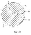
- Fig. 3B is an enlarged view of the circled portion of the mold of Fig. 3A. From this enlargement it is possible to see the channel 26 in which the resin flows around the core, after its injection into inlet port 18 (Fig. 3A). From channel 26 the resin flows into restricted channel 27 and then into gap 20 within the mold.
- Vacuum is maintained within the mold during the molding operation by appropriate sealing means, e.g., by gasket 17 provided at the interface between the two parts of the mold.
- the matrix precursor composition is caused to flow into the mold through inlet 18, by the action of positive pressure as well as by applying a vacuum to vacuum port 19.
- Heat is applied, e.g., by jacket 16, both to aid flow of the composition through empty space 13 and to promote its curing to the final polymeric matrix.
- inlet 18 and outlet 19 are closed and said material is cured and allowed to solidify, to form, together with the filaments and the tissues, if any, the body of the bobbin.
- the male and female parts of the mold are separated, and the bobbin is removed from the said male part.
- the inner surface 20 of female mold part 11 is preferably grooved, and consequently any surface created against it will also be grooved.
- the core 12 can be screwed out of the female mold part 11.
- any other arrangement such as two-parts molds, inner separable sleeve, or the like, which permit to separate the bobbin from the mold, is acceptable. Many different methods will be apparent to the skilled person, and therefore are not discussed here for the sake of brevity.
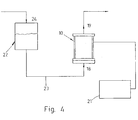
- Fig. 4 schematically illustrates a whole injection system.
- the mold 10 of Fig. 3 is connected to a vacuum line 19 on one side, and to feed inlet 18 on the other.
- a temperature controller 21 ensures that the desired temperature is maintained.
- a reservoir 22 of matrix precursr composition is connected to inlet 18 of mold 10 through line 23. Flow of the composition through line 23 is obtained, e.g., by applying an air pressure on the surface of said composition within reservoir 22, through air pressure inlet 24.
- said compositionl can be injected by using a pump or a piston or other displacement device (not shown).
- the following examples illustrate the components, viz. the precursor compositions and the filaments and tissues, of two compositematerials from which orthotropic bobbin according to the invention were made.
- the precursor compositions were cured at 80°C for 2 hours and then at 120°C for 12 hours.
- the fibers, the components of the polymeric matrix precursor composition and the polyester tissue used in this Example are given by the following Table I (%W) Manufacturer Component 50.0 DuPont Kevlar 49, Denier 7100, Type 968 18.9 CIBA-GEIGY Araldite LY-556 17.0 CIBA-GEIGY Hardener HY-917 0.1 CIBA-GEIGY Accelerator DY-070 9.5 Goodrich Chemical Hycar CTBN (1300 x 13) 4.5 Firet BV Polyester Surfacing Tissues, weight: 27 gr/m 2
- Temp (°C) Longitudinal CTE x 10 6 cm/cm x °C Transverse CTE x 10 6 cm/cm x °C 48.9 87.0 -7.1 58.9 88.5 -7.1 72.2 89.8 -7.2
- Temp (°C) Longitudinal CTE x 10 6 cm/cm x °C Transverse CTE x 10 6 cm/cm x °C 49.3 86.6 -7.2 61.3 87.6 -7.2 72.9 88.0 -7.3
- the fibers, the components of the polymeric matrix precursor composition and the polyester tissue used in this Example are given by the following Table IV. (%W) Manufacturer Component 48.6 Akzo - Nobel Twaron 1056, Drex: 8500, Filaments: 5000 19.5 CIBA-GEIGY Araldite LY-556 17.5 CIBA-GEIGY Hardener HY-917 0.1 CIBA-GEIGY Accelerator DY-070 9.7 Goodrich Chemical Hycar CTBN (1300 x 13) 4.6 Firet BV Polyester Surfacing Tissues, weight: 27 ⁇ gr/m 2
Landscapes
- Physics & Mathematics (AREA)
- General Physics & Mathematics (AREA)
- Optics & Photonics (AREA)
- Moulding By Coating Moulds (AREA)
Applications Claiming Priority (2)
| Application Number | Priority Date | Filing Date | Title |
|---|---|---|---|
| IL12051297A IL120512A (en) | 1997-03-24 | 1997-03-24 | I compare to fiber optic tanks and a method of manufacturing them |
| IL12051297 | 1997-03-24 |
Publications (1)
| Publication Number | Publication Date |
|---|---|
| EP0867739A1 true EP0867739A1 (de) | 1998-09-30 |
Family
ID=11069954
Family Applications (1)
| Application Number | Title | Priority Date | Filing Date |
|---|---|---|---|
| EP98200876A Withdrawn EP0867739A1 (de) | 1997-03-24 | 1998-03-20 | Spule für einen Behälter mit Faseroptik und zugehöriges Herstellungsverfahren |
Country Status (2)
| Country | Link |
|---|---|
| EP (1) | EP0867739A1 (de) |
| IL (1) | IL120512A (de) |
Citations (5)
| Publication number | Priority date | Publication date | Assignee | Title |
|---|---|---|---|---|
| US4995698A (en) * | 1988-12-30 | 1991-02-26 | Hughes Aircraft Company | Fiber optic canister having orthotropic, controlled thermal expansion bobbin |
| US5181270A (en) * | 1991-08-09 | 1993-01-19 | Hughes Aircraft Company | Optical fiber canister |
| US5205510A (en) * | 1990-08-03 | 1993-04-27 | Hughes Aircraft Company | Optical fiber bobbin with stress-reducing sleeve |
| US5220632A (en) * | 1992-06-24 | 1993-06-15 | Hughes Aircraft Company | Preparation of an optical fiber canister |
| EP0627380A1 (de) * | 1993-06-01 | 1994-12-07 | State Of Israel Ministry Of Defence Rafael Armament Development Authority | Verfahren und Einrichtung zur Herstellung von Spulen |
-
1997
- 1997-03-24 IL IL12051297A patent/IL120512A/en not_active IP Right Cessation
-
1998
- 1998-03-20 EP EP98200876A patent/EP0867739A1/de not_active Withdrawn
Patent Citations (5)
| Publication number | Priority date | Publication date | Assignee | Title |
|---|---|---|---|---|
| US4995698A (en) * | 1988-12-30 | 1991-02-26 | Hughes Aircraft Company | Fiber optic canister having orthotropic, controlled thermal expansion bobbin |
| US5205510A (en) * | 1990-08-03 | 1993-04-27 | Hughes Aircraft Company | Optical fiber bobbin with stress-reducing sleeve |
| US5181270A (en) * | 1991-08-09 | 1993-01-19 | Hughes Aircraft Company | Optical fiber canister |
| US5220632A (en) * | 1992-06-24 | 1993-06-15 | Hughes Aircraft Company | Preparation of an optical fiber canister |
| EP0627380A1 (de) * | 1993-06-01 | 1994-12-07 | State Of Israel Ministry Of Defence Rafael Armament Development Authority | Verfahren und Einrichtung zur Herstellung von Spulen |
Also Published As
| Publication number | Publication date |
|---|---|
| IL120512A (en) | 2002-04-21 |
| IL120512A0 (en) | 1999-03-12 |
Similar Documents
| Publication | Publication Date | Title |
|---|---|---|
| US7335012B2 (en) | Apparatus for fabricating reinforced composite materials | |
| US9399315B2 (en) | Device for manufacturing a casing made of a composite material and manufacturing method using such a device | |
| US3966523A (en) | Method of making filament reinforced composite rings from plural flat filamentary spiral layers | |
| KR930009004B1 (ko) | 광섬유 캐니스터 및 그의 제조방법 | |
| EP1674245B1 (de) | Verfahren zur Herstellung von verstärkten Verbundwerkstoffen mit niedriger Pörosität | |
| US8091603B2 (en) | One-piece inner shell for full barrel composite fuselage | |
| WO1998008370A2 (en) | Composite turbine rotor | |
| EP1900502A1 (de) | Verfahren zur Herstellung einer Verbundkante | |
| US20210292938A1 (en) | Fiber texture for a casing made of composite material with improved impact resistance | |
| US5525035A (en) | Ducted support housing assembly | |
| EP1938953A1 (de) | Verfahren zur Herstellung von Verbundstrukturen mit Kanten mit verankerten Winkeln | |
| JPH0559056B2 (de) | ||
| EP1674244B1 (de) | Verfahren zur Herstellung einer Berstschutzvorrichtung für eine Gasturbine aus faserverstärktem Verbundwerkstoff und dadurch hergestellte Berstschutzvorrichtung | |
| JP5009757B2 (ja) | 取付けフランジを有する構造体で使用するための装置 | |
| US5630971A (en) | Method and apparatus for manufacturing bobbins | |
| EP0867739A1 (de) | Spule für einen Behälter mit Faseroptik und zugehöriges Herstellungsverfahren | |
| US4211591A (en) | Production of optical fiber cables | |
| US12469626B2 (en) | Methods of manufacturing a molded, formerless multi-coil cylindrical superconducting magnet structure, and a structure as may be manufactured by such methods | |
| US4448742A (en) | Low cost thermal protection system processing | |
| CN115666893B (zh) | 用于桶形回转部件的注射工具 | |
| JPH05229018A (ja) | フィラメントワインディング成形法による筒状積層体の製造方法 | |
| LU102845B1 (en) | Boss assembly for a pressure vessel | |
| JPH10330185A (ja) | 単結晶引き上げ用ルツボ及びその製造方法 | |
| CN120697347A (zh) | 一种复合材料压力容器成型方法 | |
| JPS6334124A (ja) | 繊維強化プラスチツクス製円筒体の製造方法 |
Legal Events
| Date | Code | Title | Description |
|---|---|---|---|
| PUAI | Public reference made under article 153(3) epc to a published international application that has entered the european phase |
Free format text: ORIGINAL CODE: 0009012 |
|
| AK | Designated contracting states |
Kind code of ref document: A1 Designated state(s): DE FR GB NL |
|
| AX | Request for extension of the european patent |
Free format text: AL;LT;LV;MK;RO;SI |
|
| 17P | Request for examination filed |
Effective date: 19990222 |
|
| AKX | Designation fees paid |
Free format text: DE FR GB NL |
|
| RAP1 | Party data changed (applicant data changed or rights of an application transferred) |
Owner name: RAFAEL - ARMAMENT DEVELOPMENT AUTHORITY LTD. |
|
| 17Q | First examination report despatched |
Effective date: 20040503 |
|
| STAA | Information on the status of an ep patent application or granted ep patent |
Free format text: STATUS: THE APPLICATION IS DEEMED TO BE WITHDRAWN |
|
| 18D | Application deemed to be withdrawn |
Effective date: 20081001 |