EP0867820A2 - Eine Entwurfsumgebung und Verfahren zum Erzeugen einer realisierbaren Beschreibung eines digitalen Systems - Google Patents
Eine Entwurfsumgebung und Verfahren zum Erzeugen einer realisierbaren Beschreibung eines digitalen Systems Download PDFInfo
- Publication number
- EP0867820A2 EP0867820A2 EP98870052A EP98870052A EP0867820A2 EP 0867820 A2 EP0867820 A2 EP 0867820A2 EP 98870052 A EP98870052 A EP 98870052A EP 98870052 A EP98870052 A EP 98870052A EP 0867820 A2 EP0867820 A2 EP 0867820A2
- Authority
- EP
- European Patent Office
- Prior art keywords
- description
- recited
- objects
- data
- design apparatus
- Prior art date
- Legal status (The legal status is an assumption and is not a legal conclusion. Google has not performed a legal analysis and makes no representation as to the accuracy of the status listed.)
- Withdrawn
Links
Images







Classifications
-
- G—PHYSICS
- G06—COMPUTING OR CALCULATING; COUNTING
- G06F—ELECTRIC DIGITAL DATA PROCESSING
- G06F30/00—Computer-aided design [CAD]
- G06F30/30—Circuit design
- G06F30/32—Circuit design at the digital level
- G06F30/33—Design verification, e.g. functional simulation or model checking
- G06F30/3308—Design verification, e.g. functional simulation or model checking using simulation
-
- G—PHYSICS
- G06—COMPUTING OR CALCULATING; COUNTING
- G06F—ELECTRIC DIGITAL DATA PROCESSING
- G06F30/00—Computer-aided design [CAD]
- G06F30/30—Circuit design
-
- G—PHYSICS
- G06—COMPUTING OR CALCULATING; COUNTING
- G06F—ELECTRIC DIGITAL DATA PROCESSING
- G06F30/00—Computer-aided design [CAD]
- G06F30/30—Circuit design
- G06F30/32—Circuit design at the digital level
- G06F30/33—Design verification, e.g. functional simulation or model checking
Definitions
- the present invention is situated in the field of design environments for digital systems, generating implementable descriptions of said system.
- the invention is based on object modeling and mechanisms to refine abstract descriptions to more concrete description of the system.
- VHDL VHSIC Hardware Description Language
- VHDL is a programming environment that produces a description of a piece of hardware. Additions to standard VHDL can be to implement features of Object Oriented Programming Languages into VHDL. This was described in OO-VHDL (Computer, October 1995, pages 18-26).
- MATLAB of Mathworks Inc offers the possibility of exploration at the algorithmic level. It uses the data-vector as the basic semantical feature. However, the developed MATLAB description has no relationship to a digital hardware implementation, nor does MATLAB support the synthesis of digital circuits.
- SPW of Alta Group offers a toolkit for the simulation of these kind of systems.
- SPW is typically used to simulate data-flow semantics.
- Data-flow semantics define explicit algorithmic iteration, whereas data-vector semantics do not.
- SPW relies on an extensive library and toolkit to develop systems.
- the initial description is a block-based description. Each block used in the systems appears in two different formats, (a simulatable and a synthesizable version) which results in possible inconsistency.
- DC and BC are products of Synopsys that support system synthesis. These products do not provide sufficient algorithm exploration functions.
- the primary aim of the invention is a design environment that makes it possible to design a digital systems from a data vector description to an implementable level such a VHDL.
- a further aim is to perform this design within the same object oriented environment.
- Another aim is to provide a means comprised in said design environment for simulating behaviour at any level of development.
- a first aspect of the present invention concerns a design apparatus compiled on a computer environment for generating from a behavioral description of a system comprising at least one digital system part, an implementable description for said system, said behavioral description being represented on said computer environment as a first set of objects with a first set of relations therebetween, said implementable description being represented on said computer environment as a second set of objects with a second set of relations therebetween, said first and second set of objects being part of a design environment.
- a behavioral description is a description which substantiates the desired behavior of a system in a formal way.
- a behavioral description is not readily implementable since it is a high-level description, and it only describes an abstract version of the system that can be simulated.
- An implementable description is a more concrete description that is, in contrast to a behavioral description, detailed enough to be implemented in software to provide an approximative simulation of real-life behavior or in hardware to provide a working semiconductor circuit.
- design environment is meant an environment in which algorithms can be produced and run by interpretion or compilation.
- objects is meant a data structure which shows all the characteristics of an object from an object oriented programming language, such as described in "Object Oriented Design” (G. Booch, Benjamin/Cummings Publishing, Redwood City, Calif., 1991).
- Said first and second set of objects are preferably part of a single design environment.
- Said design environment comprises preferably an Object Oriented Programming Language (OOPL).
- OOPL Object Oriented Programming Language
- Said OOPL can be C++.
- Said design environment is preferably an open environment wherein new objects can be created.
- a closed environment will not provide the flexibility that can be obtained with an open environment and will limit the possibilities of the user.
- At least part of the input signals and output signals of said first set of objects are at least part of the input signals and output signals of said second set of objects.
- Essentially all of the input signals and output signals of said first set of objects can be essentially all of the input signals and output signals of said second set of objects.
- At least part of the input signals and output signals of said behavioral description are preferably at least part of the input signals and output signals of said implementable description. Essentially all of the input signals and output signals of said behavioral description can be essentially all of the input signals and output signals of said implementable description.
- Said first set of objects has preferably first semantics and said second set of objects has preferably second semantics.
- semantics is meant the model of computation.
- Said first semantics is preferably a data-vector model and/or a data-flow model.
- Said second semantics is preferably a signal flow graph (SFG) data structure.
- the impact in said implementable description of at least a part of the objects of said second set of objects is essentially the same as the impact in said behavioral description of at least a part of the objects of said first set of objects.
- the impact in said implementable description of essentially all of the objects of said second set of objects is essentially the same as the impact in said behavioral description of essentially all of the objects of said first set of objects.
- the design apparatus preferably further comprises means for simulating the behavior of said system said means simulating the behavior of said behavioral description, said implementable description or any intermediate description therebetween. Said intermediate description can be obtained after one or several refining steps from said behavioral description.
- At least part of said second set of objects is derived from objects belonging to said first set of objects. This can be done by using the inheritance functionalities provided in an OOPL. Essentially all of said second set of objects can be derived from objects belonging to said first set of objects.
- Said implementable description can be at least partly obtained by refining said behavioral description.
- Said implementable description can be essentially obtained by refining said behavioral description.
- said refining comprises the refining of objects.
- the design apparatus can further comprise means to derive said first set of objects from a vector description, preferably a MATLAB description, describing said system as a set of operations on data vectors, means for simulating statically or demand-driven scheduled dataflow on said dataflow description and/or means for clock-cycle true simulating said digital system using said dataflow description and/or one or more of said SFG data structures.
- a vector description preferably a MATLAB description
- said implementable description is an architecture description of said system, said system advantageously further comprising means for translating said architecture description into a synthesizable description of said system, said synthesizable description being directly implementable in hardware.
- Said synthesizable description is preferably a netlist of hardware building blocks.
- Said hardware is preferably a semiconductor chip or a electronic circuit comprising semiconductor chips.
- a synthesizable description is a description of the architecture of a semiconductor that can be synthesized without further processing of the description.
- An example is a VHDL description.
- Said means for translating said architecture description into a synthesizable description can be Cathedral-3 or Synopsys DC.
- a second aspect of the present invention is a method for designing a system comprising at least one digital part, comprising a refining step wherein a behavioral description of said system is transformed into an implementable description of said system, said behavioral description being represented as a first set of objects with a first set of relations therebetween and said implementable description being represented as a second set of objects with a second set of relations therebetween.
- Said refining step preferably comprises translating behavioral characteristics at least partly into structural characteristics.
- Said refining step can comprise translating behavioral characteristics completely into structural characteristics.
- Said method can further comprise a simulation step in which the behavior of said behavioral description, said implementable description and/or any intermediate description therebetween is simulated.
- Said refining step can comprises the addition of new objects, permitting interaction with existing objects, and adjustments to said existing objects allowing said interaction.
- said refining step is performed in an open environment and comprises expansion of existing objects.
- Expansion of existing objects can include the addition to an object of methods that create new objects. Said object is said to be expanded with the new objects.
- expandable objects allows to use meta-code generation: creating expandable objects implies an indirect creation of the new objects.
- Said behavioral description and said implementable description are preferably represented in a single design environment, said single design environment advantageously being an Object Oriented Programming Language, preferably C++.
- said first set of objects has first semantics and said second set of objects has second semantics.
- Said first semantics is preferably a data-vector model and/or a data-flow model.
- Said second semantics is preferably an SFG data structure.
- the refining step comprises preferably a first refining step wherein said behavioral description being a data-vector model is at least partly transformed into a data-flow model.
- said data-flow model is an untimed floating point data-flow model.
- Said refining step preferably further comprises a second refining step wherein said data-flow model is at least partly transformed into an SFG model.
- Said data-flow model can be completely transformed into an SFG model.
- said first refining step comprises the steps of determining the input vector lengths of input, output and intermediate signals, determining the amount of parallelism of operations that process input signals to output signals, determination of actors, edges and tokens of said data- flow model, and determining the wordlength of said tokens.
- Said step of determining the amount of parallelism can preferably comprises determining the amount of parallelism for every data vector and reducing the unspecified communication bandwidth of said data-vector model to a fixed number of communication buses in said dataflow model.
- Said step of determination of actors, edges and tokens of said data-flow model preferably comprises defining one or a group of data vectors in said first data-vector model as actors; defining data precedences crossing actor bounds, as edges, said edges behaving like queues and transporting tokens between actors; construct a system schedule and run a simulation on a computer environment.
- Said second refining step comprises preferably transforming said tokens from floating point to fixed point.
- said SFG model is a timed fixed point SFG model.
- Said second set of objects with said second set of relations therebetween are -preferably at least partly derived from said first set of objects with said first set of relations therebetween.
- Objects belonging to said second set of objects are preferably new objects, identical with and/or derived by inheritance from objects from said first set of objects, or a combination thereof.
- Said implementable description can be transformed to synthesizable code, said synthesizable code preferably being VHDL code.
- Another aspect of the present invention is a method for simulating a system, wherein a description of a system is transformed into compilable C++ code.
- said description is an SFG data structure and said compilable C++ code is used to perform clock cycle true simulations.
- Said Clock-cycle true simulation can be an expectation-based simulation, said expectation-based simulation comprising the steps of: annotating a token age to every token; annotating a queue age to every queue; increasing token age according to the token aging rules and with the travel delay for every queue that has transported the token; increasing queue age with the iteration time of the actor steering the queue, and; checking whether token age is never smaller than queue age throughout the simulation.
- Another aspect of the present invention is a hardware circuit or a software simulation of a hardware circuit designed with the design apparatus as recited higher.
- Another aspect of the present invention is a hardware circuit or a software simulation of a hardware circuit designed with the method as recited higher.
- the present invention can be described as a design environment for performing subsequent gradual refinement of descriptions of digital systems within one and the same object oriented programming language environment.
- the lowest level is semantically equivalent to a behavioral description at the register transfer (RT) level. This way, combined semantic and syntactic translations in the design flow are avoided.
- RT register transfer
- OCAPI A preferred embodiment of the invention comprising the design method according to the invention is called OCAPI. It includes both a design environment in an object oriented programming language and a design method. OCAPI differentiates from current systems that support architecture definition (SPW, COSSAP) in the way a designer is guided from the MATLAB level to the register transfer level.
- SPW support architecture definition
- COSSAP COSSAP
- Figure 13 describes a DECT Base station setup.
- Figure 14 shows the front-end processing of the DECT transceiver.
- figure 20 a dataflow target architecture is shown.
- figure 21 the simulation of one cycle in a system with three components is shown.
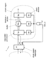
- the target architecture (5) shown in figure 2, consists of a network of interconnected application specific processors. Each processor is made up of bit-parallel datapaths. When hardware sharing is applied, also a local control component is needed to perform instruction sequencing. The processors are obtained by behavioral synthesis tools or RT level synthesis tools. In either case, circuits with a low amount of hardware sharing are targeted.
- the network is steered by one or multiple clocks. Each clock signal defines a clock region. Inside a clock region the phase relations between all register clocks are manifest. Clock division circuits are used to derive the appropriate clock for each processor.
- a hardware queue is present to transport data signals. They increase parallelism inside a clock region and maintain consistency between different streams of data arriving at one processor.
- synchronization interfaces are used. These interfaces detect the presence of data at the clock region boundary and gate clock signals for the clock region that they feed. This way, non-manifest and variable data rates in between clock regions are supported.
- the ensemble of clock dividers and handshake circuits forms a parallel scheduler in hardware, synchronizing the processes running on the bit-parallel processor.
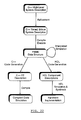
- the C++ modeling spans three subsequent levels in the design flow: the link level, the algorithm level and the architecture level.
- the transition to the last level, the circuit level, is made by automated means trough code generation.
- VHDL is used as the design language in this lowest level.
- the link level is available through data-vector modeling. Using a design mechanism called parallelism scaling, this level 1 is refined to the algorithm level.
- the algorithm level uses data-flow semantics. Using two distinct refining mechanisms in the data-flow level, we can refine this level to a register transfer level.
- Clock cycle true modeling is achieved by allocating cycle budgets and operators for each algorithm. To help the designer in this decision, operation profiling is foreseen.
- Fixed point modeling restricts the dynamic range of variables in the algorithms to a range for which a hardware operator can be devised. Signal statistics are returned by the design to help the designer with this.
- the last level uses a signal flowgraph to provide a behavioral description. Using this description synthesizable code is generated. The resulting code then can be mapped onto gates using a register-transfer design tool such as DC of Synopsys.
- the upper level of representation of a communication system is the link level. It has the following properties :
- MATLAB is used for simulation.
- MATLAB uses the data-vector as the basic data object. To represent time functions in MATLAB, they are sampled at an appropriate rate. Time is present as one of the many vector dimensions.
- the MATLAB vector addition a b +c ; can mean both sequential addition in time (if the b and c vectors are thought of as time-sequential), or parallel addition (if b and c happen to be defined at one moment in time). MATLAB simply make no distinction between these two cases.
- MATLAB has a lot of other properties that makes it the tool-of-choice within this design level :
- This data-vector restriction is to be refined to a data-flow graph representation of the system.
- Definition of the data-flow graph requires definition of all actors in the graph (actor contents as well as actor firing rules) and definition of the graph layout.
- PN pseudonoise
- DS/SS direct sequence spread-spectrum
- a vector of input data in is defined containing 8 elements. These are subsequent samples taken from the chip demodulator in the spread spectrum modem. The dimension of in thus corresponds to the time dimension.
- the input vector in is in principle infinite in length. For simulation purposes, it is restricted to a data set which has the same average properties (distribution) as the expected received data.
- the samples of in are correlated with the PN-code vector of length 4, c.
- the output vector ot thus contains 5 samples, corresponding to the five positions of in at which c can be aligned to.
- the max function locates the maximum value and position inside the correlated data. The position maxpos is subsequently used to synchronize the PN-code vector with the incoming data and thus is the desired output value of the algorithm.
- variable c This MATLAB description defines the variable c to be a data-vector containing 4 different values. This vector assignment corresponds to 4 concurrent scalar assignments. We therefore say that the maximal attainable parallelism in this statement is 4.
- each assignment is extended with a @i annotation, that indicates how the parallelism in the data vectors is ordened onto a time axis.
- a @i annotation indicates how the parallelism in the data vectors is ordened onto a time axis.
- the 8 input values inside in are provided sequentially by writing 8@1.
- the 4 values of c are provided concurrently.
- the simulation uses queues to transport signals in between the actors.
- actorl 10
- actor2 11
- maximum is selected inside actor3 (12).
- the desired dataflow format as in figure 6 is thus situated in between the multirate SDF level and the cyclostatic SDF level. It is proposed to annotate consumptions and productions in the same way as it was written down in the matlab description:
- OCAPI provides both a static scheduler and a demand-driven scheduler.
- the actor definition is based on two elements:
- the C++ signal-flowgraph representation uses a signal data-type, that can be either a registered or else an immediate value. With this data-type, expressions are formed using the conventional scalar operations. (+, -, *, shifts and logical operations). Expressions are grouped together in a signal flowgraph.
- a signal flowgraph interfaces with the system through the data-flow simulation queues.
- Several signal-flowgraphs can be grouped together to a SFG-sequence.
- a SFG sequence is an expression of behavior that spans several cycles. The specification is done through a finite state machine model, for which transition conditions can be expressed. The concept of SFG modeling is pictured in figure 7.
- the equivalent behavior is shown in figure 8.
- the behavior is modeled as a 4-cycle description.
- Three SFG's (13,14,15) are needed, in addition to a 4-state controller (16).
- the controller is modeled as a Mealy machine.
- the C++ description also illustrates some of the main contributions of OCAPI: register-transfer level aspects (signals, clocks, registers), as well as dataflow aspects simulation queues) are freely intermixed and used as appropriate.
- register-transfer level aspects signals, clocks, registers
- dataflow aspects simulation queues are freely intermixed and used as appropriate.
- time clock cycles
- the introduction of time (clock cycles) in the simulation uses an expectation-based approach. It allows to use either a high level or else an SFG-type description of the actor, and simulate the complete system clock-cycle true.
- the simulation helps the designer in finding whether his 'high-level' description matches the SFG description, and secondly, whether the system is realizable.
- Each token in the simulation is annotated with a time when it is created: the token age. Initial tokens are born at age 0, and grow older as they proceed through the dataflow graph. The unit of time is the clock cycle. Additionally, each queue in the simulation holds a queue age (say, 'the present') that is used to check the causality of the simulation: a token entering a queue should not be younger than this boundary. A queue is only able to delay tokens (registers), and therefore can only work with tokens that are older than the queue age.
- the queue age is steered by the actor that drives it.
- the iteration time corresponds the cycle budget that the designer expects to need for the detailed actor description.
- the queues driven by the actor are aged with the iteration time.
- the actor operations also increase the age of the tokens they process.
- the resulting token age is equal to the maximum of the operand token ages.
- the token age is increased by one. Besides aging by operation, aging inside of the queues is also possible by attaching a travel delay to each queue.
- a queue is also annotated with a number of expectations. These annotations reflect what the implementation of the queue as a set of communication busses should look like.
- a communication bus contains one or more registers to provide intermediate storage, and optionally also a handshake-protocol circuit.
- a queue then maps to one or more (for parallel communication) of these communication busses.
- the expectations for a simulation queue are :
- the token latency cannot be bigger than one. If it would, then the actor that provides the tokens can be designed more effectively using hardware sharing, and thus reducing the token concurrency.
- the set of operations that modify the token age are referred to as token aging rules.
- a successful clock-cycle true simulation should never fail any of these checks. In the case of such success, the expectations on the queue can be investigated more closely to devise a communication bus for it. In this description we did not mention the use of handshake protocol circuits.
- a handshake protocol circuit can be used to synchronize tokens of different age at the input of an actor.
- the current library of OCAPI allows to describe a system in C++ by building on a set of basic classes.
- This C++ description contains all information necessary to simulate the system in mind at clock cycle true level and to generate the synthesizable code for the system and the individual actors.
- the data-flow level has become transparent - it is not explicitly seen by the designer but rather it is implied through the expectations (pragma's) and the library.
- processor design is given next to experience hardware design when using OCAPI.
- the task is to design a 4-tap correlator processor that evaluates a correlation value each two cycles.
- One coefficient of the correlation pattern needs to be programmable and needs to be read in after a control signal is asserted.
- the listing in figure 11 gives the complete FSMD model of this processor.
- the top of the listing shows how types are declared in OCAPI.
- the type T_sample is 8 bits wide and has 6 bits beyond the binary point.
- a signed, wrap-around and truncating representation is assumed by default. This can be easily changed, as for instance in
- coefficient declarations These are specified as plain double types, since they will be automatically quantized when read in into the coefficient registers. It is possible to intermix existing C/C++ constructs and types with new ones.
- the FSMD definition of the correlator processor is shown. This definition requires: the specification of the instruction set that is processed by this processor, and a specification of the control behavior of the processor. For each of these, OCAPI uses dedicated objects. First, the instruction set is defined. Each instruction performs data processing on signals, which must be defined first. The definitions include plain signals ( sample_in and corr out ), registers ( accu ), and register arrays ( coef[] and sample [] ) . Next, each of the instructions are defined.
- a definition is started by creating a SFG object. All signal expressions that come after such an SFG definition are considered to make up part of it.
- a SFG definition is closed simply by defining a new SFG object.
- the first instruction, initialize_coefs initializes the coefficient registers coef[] .
- the for loop allows to express the initialization in a compact way.
- the initialize_coefs instruction is also equivalent to
- the second instruction programs the value of the first coefficient.
- the new value, coef_in is read from an input port of the FSMD with the same name. Beyond this port, we are 'outside' of the timed FSMD description and use dataflow semantics, and communicate via queues.
- the third and fourth instruction, correl_1 and correl_2 describe the two phases of the correlation. It is very easy to express complex expressions just by using C++ operators. Also, a cast operation is included that limits the precision of the intermediate expression result. Although this is for minor importance for simulation, it has strong influence on the hardware synthesis result.
- the instruction read_sample shifts the data delay line. In addition to a for loop, an if expression is used to express the boundary value for the delay line.
- the transition condition always is always true, while a transition condition like cnd(load) will be true whenever the register load contains a one.
- the resulting fsm description is returned to OCAPI by the last return statement.
- the simulator and code generator can now process the object hierarchy in order to perform semantical checks, simulation, and code generation.
- the translation to synthesizable VHDL and Cathedral-3 code is automatic and needs no extra designer effort.
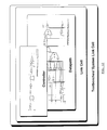
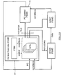
- the resulting circuit for datapath and controller is shown in figure 12.
- the hierarchy of the generated code that is provided by OCAPI is also indicated.
- Each controller and datapath are interlinked using a link cell.
- the link cell itself can be embedded into an automatically generated testbench or also in the system link cell that interconnects all components.
- the design consists of a digital radiolink transceiver ASIC, residing in a DECT base station (20) (figure 13).
- the chip processes DECT burst signals, received through a radio frequency front-end RF (21).
- the signals are equalized to remove the multipath distortions introduced in the radio link (22).
- they are passed to a wire-link driver DR (23), that establishes communication with the base station controller BSC (24).
- the system is also controlled locally by means of a control component CTL (25).
- the most important degree of freedom in this design process is the target architecture, which must be chosen such that the requirements are met. Due to the critical design time, a maximum of control over the design process is required. To achieve this, a programming approach to implementation is used, in which the system is modelled in C++.
- the object oriented features of this language allows to mix high-level descriptions of undesigned components with detailed clock-cycle true, bit-true descriptions.
- appropriate object modelling allows the detailed descriptions to be translated to synthesizable HDL automatically.
- verification testbenches can be generated automatically in correspondence with the C++ simulation.
- the result of this design effort is a 75 Kgate chip with a VLIW architecture, including 22 datapaths, each decoding between 2 and 57 instructions, and including 7 RAM cells.
- the chip has a 194 die area in 0.7 CMOS technology.
- the C++ programming environment allows to obtain results faster then existing approaches.
- register transfer design environments such as , it will be shown that C++ allows to obtain more compact, and consequently less error prone descriptions of hardware.
- High level synthesis environments could solve this problem but have to fix the target architecture on beforehand.
- sudden changes in target architecture can occur due to hard initial requirements, that can be verified only at system implementation.
- This model includes two types of description: high-level untimed ones and detailed timed blocks. Using such a model, a simulation mechanism is constructed. It will be shown that the proposed approach outperforms current synthesis environments in code size and simulation speed. Following this, HDL code generation issues and hardware synthesis strategies are described.
- the DECT transceiver is best described with a set of concurrent processes. Each process translates to one component in the final system implementation.
- processes execute using data flow simulation semantics. That is, a process is described as an iterative behavior, where inputs are read in at the start of an iteration, and outputs are produced at the end. Process execution can start as soon as the required input values are available.
- the first one is a high level description, and can be expressed using procedural C++ constructs.
- a firing rule is also added to allow dataflow simulation .
- the second flavour of processes is described at register transfer level. These processes operate synchronously to the system clock. One iteration of such a process corresponds to one clock cycle of processing.
- a dataflow scheduler is used to simulate a system that contains only untimed blocks. This scheduler repeatedly checks process firing rules, selecting processes for execution as their inputs are available.
- a cycle scheduler When the system also contains timed blocks, a cycle scheduler is used instead.
- the cycle scheduler manages to interleave execution of multi-cycle descriptions, but can incorporate untimed blocks as well.
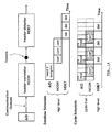
- Figure 14 shows the front-end processing of the DECT transceiver, and the difference between data-flow and cycle scheduling.
- the received signals are sampled by and A/D, and correlated with a unique header pattern in the header correlator HCOR.
- the resulting correlations are detected inside a header detector block HDET.
- a simulation with high level descriptions uses the dataflow scheduler.
- An example dataflow schedule is seen in the middle of the figure.
- the A/D high level description produces 3 tokens, which are put onto the interconnect communication queue.
- the correlator high level description can be fired three times, followed by the detector processing.
- Finite Wordlength effects are simulated with a C++ fixed point library. It has been shown that the simulation of these effects is easy in C++ . Also, the simulation of the quantization rather than the bitvector representation allows significant simulation speedups .
- the behavior is modelled with a mixed control/data processing description, under the form of a finite state machine coupled to a datapath. This model is common in the synthesis community. In high throughput telecommunications circuits such as the ones in the DECT transceiver ASIC, it most often occurs that the desired component architecture is known before the hardware description is made. The FSMD model works well for these type of components.
- wordlength modelling and cycle true modelling are available in the programming environment as separate class hierarchies. Therefore, fixed point modelling can be applied equally well to high level descriptions.
- FIG. 15 a part of the central VLIW controller description for the DECT transceiver ASIC is shown in figure 15.
- the top shows a Mealy type finite state machine (30).
- the signal flowgraph descriptions (31) below it are executed.
- the two states execute and hold correspond to operational and idle states of the DECT system respectively.
- the conditions are stored in registers inside the signal flowgraphs. In this case, the condition holdrequest is related to an external pin.
- instructions are distributed to the datapaths. Instructions are retrieved out of a lookup table, addressed by a program counter. When holdrequest is asserted, the current instruction is delayed for execution, and the program counter PC is stored in an internal register. During a hold, a nop instruction is distributed to the datapaths to freeze the datapath state. As soon as holdrequest is removed, the stored program counter holdpc addresses the lookup table, and the interrupted instruction is issued to the datapaths for execution.
- Signals are the information carriers used in construction of a timed description. Signals are simulated using C++ sig objects. These are either plain signals or else registered signals. In the latter case the signals have a current value and next value, which is accessed at signal reference and assignment respectively. Registered signals are related to a clock object clk that controls signal update. Both types of signals can be either floating point values or else simulated fixed point values.
- signals are assembled to expressions.
- the parser of the C++ compiler is reused to construct the signal flowgraph data structure.
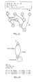
- FIG. 17 An example of this is shown in figure 17.
- the top of the figure shows a C++ fragment (40). Executing this yields the data structure (41) shown below it. It is seen that
- a set of sig expressions can be assembled in a signal flow graph (SFG).
- FSG signal flow graph
- desired inputs and outputs of the signal flowgraph have to be indicated. This allows to do semantical checks such as dangling input and dead code detection, which warn the user of code inconsistency.
- An SFG has well defined simulation semantics and represents one clock cycle of behavior.
- Figure 18 shows a graphical and C++-textual description of the same FSM. The correspondence is obvious.
- To describe an equivalent FSM in an event driven HDL one usually has to follow the HDL simulator semantics, and for example use multi-process modelling.
- C++ the semantics can be adapted depending on the type of object processed, all within the same piece of source code.
- the final system architecture of the DECT transceiver is shown in figure 19. It consists of a central (VLIW) controller (50), a program counter controller (51) and 22 datapath blocks. Each of these are modelled with the combined control/data processing shown above. They exchange data signals that, depending on the particular block, are interpreted as instructions, conditions or signal values. By means of these interconnected FSMD machines, a more complex machine is constructed.
- DECT transceiver For the DECT transceiver, there is a severe latency requirement.
- a dataflow target architecture was chosen (figure 20), which is common for this type of telecommunications signal processing.
- the individual components are controlled locally and data driven.
- the header detector processor signals a DECT header start (a correlation maximum), as soon as it is sure that a global maximum is reached.
- a cycle scheduler is used instead of a dataflow scheduler.
- the cycle scheduler creates the illusion of concurrency between components on a clock cycle basis.
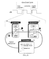
- the operation of the cycle scheduler is best illustrated with an example.
- the simulation of one cycle in a system with three components is shown.
- the first two, components 1 (60) and 2 (61), are timed descriptions constructed using fsm and sfg objects.
- Component 3 (62) on the other hand is decribed at high level using a firing rule and a behavior.
- a loop of detailed (timed) and high level (untimed) components occurs for instance in the RAM cells that are attached to the datapaths. In that case, the RAM cells are described at high level while the datapaths are described at clock cycle true level.
- the simulation of one clock cycle is done in three phases.
- Traditional RT simulation uses only two; the first being an evaluation phase, and the second being a register update phase.
- the three phases used by the cycle scheduler are a token production phase, an evaluation phase and a register update phase.
- the three-phase simulation mechanism is needed to avoid apparent deadlocks that might exist at the system level. Indeed, in the example there is a circular dependency in between components 1, 2, and 3, and a dataflow scheduler can no longer select which of the three components should be executed first. In dataflow simulation, this is solved by introducing initial tokens on the data dependencies. Doing so would however require us to devise a buffer implementation for the system interconnect, and introduce an extra code generator in the system.
- the cycle scheduler avoids this by creating the required initial tokens in the token production phase.
- Each of the phases operates as follows.
- the evaluation phase of the three-phase simulation is an iterative process. If a pre-set amount of iterations have passed, and there are still unfired components, then the system is declared to be deadlocked. This way, the cycle scheduler identifies combinatorial loops in the system.
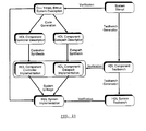
- the clock-cycle true, bit-true description of system components serves a dual purpose. First, the descriptions have to be simulated in order to validate them. Next, the descriptions have also to be translated to an equivalent, synthesizable HDL description.
- the C++ description itself can be treated in two ways in the programming environment. In case of a compiled code approach, the C++ description is translated to directly executable code. In case of an interpreted approach, the C++ description is preprocessed by the design system and stored as a data structure in memory.
- This data structure can next be interpreted by a simulator for quick verification purposes.
- the same data structure is also processed by a code generator to yield two different descriptions.
- a C++ description can be regenerated to yield an application-specific and optimized compiled code simulator. This simulator is used for extensive verification of the design because of the efficient simulation runtimes.
- a synthesizable HDL description can also be generated to arrive at a gate-level implementation.
- the C++ modelling gains a factor of 5 in code size (for the interpreted-object approach) over RT-VHDL modeling. This is an important advantage given the short design cycle for the system.
- Compiled code C++ on the other hand provides faster simulation and smaller process size then RT-VHDL.
- a controller description and a datapath description is generated, in correspondence with the C++ description. This is done because we rely on separate synthesis tools for both parts, each one optimized towards controller or else datapath synthesis tasks.
- Controller synthesis on the other hand is done by logic synthesis such as Synopsys DC.
- logic synthesis such as Synopsys DC.
- FSM synthesis pure logic synthesis
- This tool produces efficient results.
- the combined netlists of datapath and controller are also post-optimized by Synopsys DC to perform gate-level netlist optimizations. This divide and conquer strategy towards synthesis allows each tool to be applied at the right place.
- system stimuli are also translated into testbenches that allow to verify the synthesis result of each component.
- the final implementation can also be verified using a generated system testbench.
Landscapes
- Engineering & Computer Science (AREA)
- Computer Hardware Design (AREA)
- Physics & Mathematics (AREA)
- Theoretical Computer Science (AREA)
- Evolutionary Computation (AREA)
- Geometry (AREA)
- General Engineering & Computer Science (AREA)
- General Physics & Mathematics (AREA)
- Management, Administration, Business Operations System, And Electronic Commerce (AREA)
- Design And Manufacture Of Integrated Circuits (AREA)
Applications Claiming Priority (4)
| Application Number | Priority Date | Filing Date | Title |
|---|---|---|---|
| US3907997P | 1997-03-14 | 1997-03-14 | |
| US39079P | 1997-03-14 | ||
| US4112197P | 1997-03-20 | 1997-03-20 | |
| US41121P | 1997-03-20 |
Publications (2)
| Publication Number | Publication Date |
|---|---|
| EP0867820A2 true EP0867820A2 (de) | 1998-09-30 |
| EP0867820A3 EP0867820A3 (de) | 2000-08-16 |
Family
ID=26715800
Family Applications (1)
| Application Number | Title | Priority Date | Filing Date |
|---|---|---|---|
| EP98870052A Withdrawn EP0867820A3 (de) | 1997-03-14 | 1998-03-13 | Eine Entwurfsumgebung und Verfahren zum Erzeugen einer realisierbaren Beschreibung eines digitalen Systems |
Country Status (2)
| Country | Link |
|---|---|
| EP (1) | EP0867820A3 (de) |
| JP (1) | JPH113367A (de) |
Cited By (8)
| Publication number | Priority date | Publication date | Assignee | Title |
|---|---|---|---|---|
| US6152612A (en) * | 1997-06-09 | 2000-11-28 | Synopsys, Inc. | System and method for system level and circuit level modeling and design simulation using C++ |
| WO2001053999A3 (en) * | 2000-01-24 | 2002-09-06 | Radioscape Ltd | Method of designing, modelling or fabricating a communications baseband stack |
| WO2001053932A3 (en) * | 2000-01-24 | 2002-09-12 | Radioscape Ltd | Software for designing, modelling or performing digital signal processing |
| WO2002008966A3 (en) * | 2000-07-21 | 2003-01-09 | Telecom Italia Lab Spa | Method and system for verifying modules destined for generating circuits |
| WO2001095161A3 (en) * | 2000-06-02 | 2003-10-02 | Virtio Corp | Method and system for virtual prototyping |
| US7012448B2 (en) | 2001-04-07 | 2006-03-14 | The University Court Of The University Of Dundee | Integrated circuit and related improvements |
| US8893080B2 (en) | 2012-08-15 | 2014-11-18 | Telefonaktiebolaget L M Ericsson (Publ) | Parallelization of dataflow actors with local state |
| CN114519319A (zh) * | 2021-12-30 | 2022-05-20 | 中国人民解放军国防科技大学 | 一种基于高层建模的混合发射队列设计实现方法及系统 |
Families Citing this family (5)
| Publication number | Priority date | Publication date | Assignee | Title |
|---|---|---|---|---|
| US4724216A (en) * | 1984-09-11 | 1988-02-09 | Nova Biomedical Corporation | Method for measuring calcium |
| CH672603A5 (de) * | 1987-04-09 | 1989-12-15 | Maag Zahnraeder & Maschinen Ag | |
| JP4237661B2 (ja) | 2004-03-25 | 2009-03-11 | 株式会社東芝 | システムlsiの設計支援システム及び設計支援方法 |
| US7958417B2 (en) * | 2008-01-30 | 2011-06-07 | Alcatel-Lucent Usa Inc. | Apparatus and method for isolating portions of a scan path of a system-on-chip |
| FR3093208B1 (fr) * | 2019-02-27 | 2021-12-03 | Commissariat Energie Atomique | Procédé de validation d’un système flots de données |
Family Cites Families (2)
| Publication number | Priority date | Publication date | Assignee | Title |
|---|---|---|---|---|
| US5163016A (en) * | 1990-03-06 | 1992-11-10 | At&T Bell Laboratories | Analytical development and verification of control-intensive systems |
| US5493508A (en) * | 1994-06-01 | 1996-02-20 | Lsi Logic Corporation | Specification and design of complex digital systems |
-
1998
- 1998-03-13 JP JP10106862A patent/JPH113367A/ja active Pending
- 1998-03-13 EP EP98870052A patent/EP0867820A3/de not_active Withdrawn
Non-Patent Citations (1)
| Title |
|---|
| OEHLER P.; GRIMM G.; WALDSCHMIDT K.: "KANDIS-a tool for construction of mixed analog/digital systems", DESIGN AUTOMATION CONFERENCE, 18 September 1995 (1995-09-18), LOS ALAMITOS, CA, USA, IEEE COMPUT. SOC, US, pages 14 - 19, XP010192891 * |
Cited By (11)
| Publication number | Priority date | Publication date | Assignee | Title |
|---|---|---|---|---|
| US6152612A (en) * | 1997-06-09 | 2000-11-28 | Synopsys, Inc. | System and method for system level and circuit level modeling and design simulation using C++ |
| WO2001053999A3 (en) * | 2000-01-24 | 2002-09-06 | Radioscape Ltd | Method of designing, modelling or fabricating a communications baseband stack |
| WO2001053932A3 (en) * | 2000-01-24 | 2002-09-12 | Radioscape Ltd | Software for designing, modelling or performing digital signal processing |
| WO2001095161A3 (en) * | 2000-06-02 | 2003-10-02 | Virtio Corp | Method and system for virtual prototyping |
| US7613599B2 (en) | 2000-06-02 | 2009-11-03 | Synopsys, Inc. | Method and system for virtual prototyping |
| US7970596B2 (en) | 2000-06-02 | 2011-06-28 | Synopsys, Inc. | Method and system for virtual prototyping |
| WO2002008966A3 (en) * | 2000-07-21 | 2003-01-09 | Telecom Italia Lab Spa | Method and system for verifying modules destined for generating circuits |
| US7012448B2 (en) | 2001-04-07 | 2006-03-14 | The University Court Of The University Of Dundee | Integrated circuit and related improvements |
| US8893080B2 (en) | 2012-08-15 | 2014-11-18 | Telefonaktiebolaget L M Ericsson (Publ) | Parallelization of dataflow actors with local state |
| CN114519319A (zh) * | 2021-12-30 | 2022-05-20 | 中国人民解放军国防科技大学 | 一种基于高层建模的混合发射队列设计实现方法及系统 |
| CN114519319B (zh) * | 2021-12-30 | 2024-09-10 | 中国人民解放军国防科技大学 | 一种基于高层建模的混合发射队列设计实现方法及系统 |
Also Published As
| Publication number | Publication date |
|---|---|
| JPH113367A (ja) | 1999-01-06 |
| EP0867820A3 (de) | 2000-08-16 |
Similar Documents
| Publication | Publication Date | Title |
|---|---|---|
| US6233540B1 (en) | Design environment and a method for generating an implementable description of a digital system | |
| US7006960B2 (en) | Design apparatus and a method for generating an implementable description of a digital system | |
| Coussy et al. | Gaut: A high-level synthesis tool for dsp applications: From c algorithm to rtl architecture | |
| Staunstrup et al. | Hardware/software co-design: principles and practice | |
| Bolsens et al. | Hardware/software co-design of digital telecommunication systems | |
| Gajski et al. | Introduction to high-level synthesis | |
| De Micheli et al. | The Olympus synthesis system | |
| Gauthier et al. | Automatic generation and targeting of application-specific operating systems and embedded systems software | |
| US6021266A (en) | Method of designing an integrated circuit using scheduling and allocation with parallelism and handshaking communication, and an integrated circuit designed by such method | |
| Liao | Towards a new standard for system-level design | |
| US20100286976A1 (en) | Systems and Methods for Logic Verification | |
| Kambe et al. | A c-based synthesis system, bach, and its application (invited talk) | |
| Muttillo et al. | SystemC-based co-simulation/analysis for system-level hardware/software co-design | |
| Lavagno et al. | Design of embedded systems | |
| JPH113367A (ja) | デジタルシステムのインプリメント可能な記述を生成する設計環境および方法 | |
| Vahid et al. | Functional partitioning improvements over structural partitioning for packaging constraints and synthesis: tool performance | |
| Chevalier et al. | SPACE: A hardware/software SystemC modeling platform including an RTOS | |
| Ortega et al. | Models and methods for hw/sw intellectual property interfacing | |
| Asar | Towards a multi-formalism framework for architectural synthesis: The ASAR project | |
| Kambe et al. | Trend of system level design and an approach to C-based design | |
| Baganne et al. | A multi-level design flow for incorporating IP cores: Case study of 1D wavelet IP integration | |
| Jantsch et al. | Models of computation in the design process | |
| Marongiu et al. | The HARWEST compiling environment: Accessing the FPGA world through ANSI-C programs | |
| Lis et al. | Structured modeling for VHDL synthesis | |
| de Dinechin et al. | Design of highly parallel architectures with alpha and handel |
Legal Events
| Date | Code | Title | Description |
|---|---|---|---|
| PUAI | Public reference made under article 153(3) epc to a published international application that has entered the european phase |
Free format text: ORIGINAL CODE: 0009012 |
|
| AK | Designated contracting states |
Kind code of ref document: A2 Designated state(s): BE DE DK ES FI FR GB IT NL SE |
|
| AX | Request for extension of the european patent |
Free format text: AL;LT;LV;MK;RO;SI |
|
| PUAL | Search report despatched |
Free format text: ORIGINAL CODE: 0009013 |
|
| AK | Designated contracting states |
Kind code of ref document: A3 Designated state(s): AT BE CH DE DK ES FI FR GB GR IE IT LI LU MC NL PT SE |
|
| AX | Request for extension of the european patent |
Free format text: AL;LT;LV;MK;RO;SI |
|
| 17P | Request for examination filed |
Effective date: 20000927 |
|
| AKX | Designation fees paid |
Free format text: BE DE DK ES FI FR GB IT NL SE |
|
| 17Q | First examination report despatched |
Effective date: 20060720 |
|
| RAP1 | Party data changed (applicant data changed or rights of an application transferred) |
Owner name: IMEC |
|
| STAA | Information on the status of an ep patent application or granted ep patent |
Free format text: STATUS: THE APPLICATION IS DEEMED TO BE WITHDRAWN |
|
| 18D | Application deemed to be withdrawn |
Effective date: 20090609 |