EP0868044A2 - Système de transmission optique bidirectionnelle - Google Patents
Système de transmission optique bidirectionnelle Download PDFInfo
- Publication number
- EP0868044A2 EP0868044A2 EP98301600A EP98301600A EP0868044A2 EP 0868044 A2 EP0868044 A2 EP 0868044A2 EP 98301600 A EP98301600 A EP 98301600A EP 98301600 A EP98301600 A EP 98301600A EP 0868044 A2 EP0868044 A2 EP 0868044A2
- Authority
- EP
- European Patent Office
- Prior art keywords
- optical
- carrier
- spectral characteristic
- laser
- wavelength
- Prior art date
- Legal status (The legal status is an assumption and is not a legal conclusion. Google has not performed a legal analysis and makes no representation as to the accuracy of the status listed.)
- Granted
Links
Images

Classifications
-
- H—ELECTRICITY
- H04—ELECTRIC COMMUNICATION TECHNIQUE
- H04J—MULTIPLEX COMMUNICATION
- H04J14/00—Optical multiplex systems
- H04J14/02—Wavelength-division multiplex systems
- H04J14/0298—Wavelength-division multiplex systems with sub-carrier multiplexing [SCM]
-
- H—ELECTRICITY
- H04—ELECTRIC COMMUNICATION TECHNIQUE
- H04B—TRANSMISSION
- H04B10/00—Transmission systems employing electromagnetic waves other than radio-waves, e.g. infrared, visible or ultraviolet light, or employing corpuscular radiation, e.g. quantum communication
- H04B10/25—Arrangements specific to fibre transmission
- H04B10/2589—Bidirectional transmission
Definitions
- the present invention is directed to an optical transmission system. More specifically, the present invention is directed to a bidirectional optical transmission system in which sub-carrier multiplexing is employed.
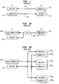
- FIG. 1 An example of one such known configuration is illustrated in FIG. 1.
- "bi-direction" refers to the fact that information can be sent between point A and point B in either direction.
- the system actually consists of two uni-directional transmission systems combined together.
- a first optical fiber 120 carries information from transmitter 130 at location B to receiver 100 at location A.
- This first uni-directional transmission system is combined with a second uni-directional transmission system that employs a second optical fiber 121 to carry transmissions from transmitter 110 at location A to receiver 131 at location B.
- the obvious problem with this configuration is the need for two separate optical fibers to carry the information between points A and B. It is desirable to provide information between the locations over a single optical fiber if possible.
- FIG. 2A An example of this configuration is illustrated in FIG. 2A.
- a laser transmitter 200 and a receiver 210 are positioned at location C.
- the laser transmitter transmits an optical signal over optical fiber 220 to a second location D.
- Modulator/receiver 230 receives the information signal from the optical fiber 220 and then modulates the carrier signal received and sends it back along the same optical fiber 220.
- a splitter 240 then permits a receiver 210 at location C to receive the modulated returned optical carrier that contains information being transmitted from location D.
- a receiver 210 at location C receives the modulated returned optical carrier that contains information being transmitted from location D.
- each receiver 235 1 to 235 N is adapted to receive information from one of the N sub-carriers. Also, each transmitter 250 1 to 250 N transmits back to receiver 215 using a sub-carrier frequency.
- a phenomenon known as "optical beat-interference” can cause severe system impairments (as described in "Optical Interference in Light Wave Subcarrier Multiplexing Systems employing Multiple Optical Carriers.”
- the present invention provides the desired bi-directional transmission system.
- the present invention achieves the bi-directional transmission capability with reduction or avoidance of optical beat interference by providing a unique combination of transmitters and receivers at the access points of the network.
- the transmitters at two different locations along the single optical fiber produce transmission signals in accordance with two different optical spectra.
- the optical spectral characteristics for the two transmitters are selected so as to assure that the wavelength of the optical carriers are different during the operation of the system. This avoids the production of optical beat interference.
- the selection is made so as to assure that even as the wavelength of the transmitters may vary based on certain stimuli such as temperature (such variation also being referred to as drift), the wavelengths will have a very low probability of overlapping thereby insuring a reduction or avoidance of optical beat interference.
- the optical carriers for the two transmitters are specifically selected to have optical frequencies which differ by more than the maximum frequency employed as a sub-carrier (fmaxsc).
- ⁇ f/c ⁇ 2 ). This requirement must be increased to account for the laser linewidth (variations in the optical frequency due to noise), chirp (variations in the optical frequency due to modulation of the optical carrier), and drift.
- Temperature controllers could be provided with these transmitters so as to stabilize the lasers to avoid drift. However, if the wavelength difference is sufficient, then even without temperature control the effects of optical beat interference should be minimized.
- a multiple frequency laser also known as a multimode laser
- the optical carriers must be selected so that each optical frequency of one carrier differs from all of the optical frequencies of the other carrier by f maxsc .
- the characteristics of the optical spectra differ in that the mode spacing (the difference in wavelength between two frequencies of one multiple frequency laser) of the two lasers differ sufficiently that even with drift the optical spectra of the two lasers will never coincide at all of the optical frequencies.
- This difference in mode spacing can be achieved either by using two Fabry-Perot lasers of different lengths or by employing a Fabry-Perot laser and a single frequency laser such as a distributed feedback laser.
- the present invention assures that bi-directional transmission in the sub-carrier multiplexing environment is attainable.
- FIG. 1 illustrates a prior art bi-directional two-optical fiber configuration.
- FIG. 2A illustrates a prior art bi-directional transmission system over a single optical fiber.
- FIG. 2B illustrates a known passive optical network employing sub-carrier multiplexing.
- FIG. 3 illustrates an embodiment of the present invention.
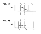
- FIGS. 4A and 4B illustrate sample mode spacing arrangements employable in the embodiment of FIG. 3.
- FIG. 3 An embodiment of a bi-directional optical transmission system in accordance with the present invention is illustrated in FIG. 3. Two locations “I” and “II” are coupled together via a single optical fiber 350. In general terms, each of the locations contains essentially the same equipment, however, the differences and distinctions between the locations will be described.
- the transmitter 370 includes a RF (radio frequency) source 303 and a DC source represented by Idc.
- RF radio frequency
- Idc DC source
- the DC source insures that the laser is on, i.e., is emitting light, so that an optical carrier is present.
- the RF signals modulate the optical carrier produced by laser 301. This provides a sub-carrier multiplexed signal.
- this transmitter can be a directly modulated laser that provides one or more RF sub-carriers on the optical carrier.
- the receiver module 360 can be a transmitter that includes a laser that first produces an optical carrier signal and an optical modulator placed downstream of the laser which modulates the optical carrier with sub-carrier signals.
- the receiver module 360 includes an optical receiver 300 for optical-to-electrical conversion. This sends the appropriate electrical signal to the demodulator 302 which can discern the appropriate sub-carrier(s) from the received signal and produce the appropriate corresponding electrical information.
- a beam splitting device 304 couples the receiver module 360 and the transmitter 370 to the optical fiber 350. As a consequence, the transmission signal from the transmitter 370 is sent to the location II via the beam splitter 304 and the optical fiber 350 while the receiver module 360 receives the signal sent by location II via the beam splitter 304' and optical fiber 350.
- the transceiver at location II consists of similar components.
- transmitter 370' includes a laser 307, RF source 308, and DC source.
- This transmitter provides a subcarrier multiplexed optical signal to beam splitter 304' for transmission along optical fiber 350.
- the beam splitter 304' receives the signal produced by location I and provides it to optical receiver 305 which then converts the optical signal to an electrical one for processing by demodulator 306 in a receiver module 360'.
- optical beat interference has been studied in systems where the optical carriers are of comparable strength such as that depicted in FIG. 2B. It has also been studied in bidirectional systems such as that depicted in FIG. 2A. The bidirectional system of the present invention differs from these known systems.
- the interfering optical carrier is ⁇ 20dB weaker-than the desired optical carrier (assuming ⁇ 10dB optical loss along fiber 350) and it is only present at receiver 360 because Rayleigh back scattering in the fiber 350 reflects light from transmitter 370 into receiver 360.
- the present invention differs from the system of FIG. 2A because different optical carriers are employed - reducing the likelihood that there will be optical interference. Additionally, in FIG. 2A the interfering light is approximately 10dB lower than the desired signal light at receiver 210 (again assuming a 10dB loss in the optical fiber) . Because of these differences the optical beat interference in the system of FIG. 2A is much larger and more predictable than the optical beat interference in the proposed system.
- this phenomenon can be obviated by assuring that the transmitters 370 and 370' have different optical spectra, mainly, that the characteristics of the transmitters are such as to assure that the wavelengths of transmission in the operational region will not overlap during the operation of the system.
- the optical spectral characteristics are made different by providing lasers 301 and 307 which provide different optical carrier wavelengths.
- laser 301 could provide an optical carrier signal on which the subcarriers would be modulated where the optical carrier would have the wavelength ⁇ 1 equal to 1300 nm.
- the optical carrier produced by laser 307 could be selected to be 1301 nm. This difference in wavelength is such that the characteristics of the optical spectra are sufficiently different (greater than 100 GHz) to insure that the wavelengths will not overlap during the operation of the two transceivers and that optical beat interference will not arise.
- the present invention can provide bi-directional transmission over a single optical fiber with minimized concern for optical beat interference.
- the laser optical carrier output may drift.
- lasers may produce optical carrier signals having different wavelengths depending on the temperatures to which the laser is subjected.
- the wavelength of the optical carrier, produced, for example, by laser 301 at location I may drift toward the wavelength produced by laser 307 at location II. Therefore, if the differences in wavelengths are not defined to be an adequate amount, then it is possible that with certain temperature drifts an overlap condition might arise which might produce optical beat interference.
- One solution to this problem is to provide temperature controllers at the locations at which the lasers are provided.
- the temperature controllers would insure that the occurrence of drift would be less likely.
- DFB distributed feedback laser
- An alternative embodiment of the present invention addresses this problem in a different manner without requiring temperature controllers.
- the same effect that is, the reduction of the likelihood of the overlap of optical carrier wavelengths can be achieved by providing lasers at the different locations with different mode spacing characteristics.
- the mode spacing characteristics of a Fabry-Perot laser that is the difference between the wavelengths at which the device is likely to lase given certain phenomenon, differ depending upon the length of the resonant cavity of the laser.
- FIGS. 4A and 4B Examples of the mode spacing characteristics of lasers are shown in FIGS. 4A and 4B.
- the mode spacing characteristic in FIG. 4A corresponds to laser 301 and the mode spacing characteristic of FIG. 4B corresponds to laser 307.
- laser 301 may have four different wavelengths ⁇ 1 - ⁇ 4 at which lasing occurs.
- laser 307 has a different mode spacing characteristic which only permits lasing at wavelengths ⁇ 5 - ⁇ 7 .
- the chirp of the laser must also be considered in choosing the optimal mode spacing.
- large amounts of chirp will reduce the spectral noise density due to optical beat interference, which is advantageous in most cases (in cases where the bandwidth of the signals is less than the bandwidth of the noise).
- large amounts of chirp will reduce the spectral noise density of the noise produced by the aligned modes, however, this must be weighed against the broadening of the other modes.
- the broadening of the modes must be taken into account when choosing the mode spacing, otherwise modes which are not aligned when the laser is not modulated will produce noise in the signal band when modulated.
- multimode lasers with different mode spacing one can insure that not all the light in either laser contributes to the interference within the signal band. It is therefore advantageous to use multimode lasers which do not have a dominant mode. Therefore, in designing lasers for this system the fraction of optical power in the dominant mode should be minimized (i.e., lasers with many equal strength modes are better than lasers with few modes, or lasers with many modes which have the optical power primarily in just a few modes).
- Fabry-Perot semiconductor lasers In Fabry-Perot semiconductor lasers this design consideration leads to the choice of an active medium with a large gain-bandwidth so that many modes will have approximately equal gain, and therefore equal strength (current commercial devices employ strained-layer multiple-quantum-well active regions, and have a larger gain bandwidth than devices manufactured just a few years ago with bulk-active sections). Additionally, using lasers with smaller mode spacing is favored, as this enables more modes to fit within a given gain-bandwidth. In Fabry-Perot lasers the mode-spacing is set by the length of the laser cavity. In optimizing the length other factors must be considered, such as the laser threshold current, the laser chirp (as mentioned earlier, the laser chirp must be considered in choosing optimal mode spacing) and the laser cost.
- This invention can also be employed in an environment where more than one location is involved.
- the embodiment is applicable to a mini-fiber-node (mFN) architecture (described in "Mini-fiber-node hybrid fiber coax networks for two-way broadband access" by Lu et al., OFC '96 Technical Digest, pp. 143-144) that uses one fiber for both upstream and downstream transmission and uses lasers with different optical spectral characteristics in the head end and the remote nodes.
- mFN architecture is a fiber-to-the-curb overlay to a CATV (Cable TV) system.
- CATV Code TV
- each node in the architecture might serve on the order of 30 homes. Employment of this invention would reduce the amount of fiber required.
- optical beat interference can also occur if each of the laser sources operates at the same optical carrier wavelength even though each of the optical carriers may be carrying different sub-carrier signals.
- a first transmitter operates with an optical carrier ⁇ 1 modulated with subcarriers f 1 , f 2 and f 3 while a second transceiver has a laser also providing an optical carrier of ⁇ 1 where the modulator signals are subcarriers f 3 , f 4 and f 5
- the same optical beat interference phenomenon can occur and disrupt transmissions even though different subcarriers are being employed.
- the present invention can be adapted to reduce the problem of optical beat interference in this configuration as well.
- the two laser devices for the transmitters in this system could have different optical spectral characteristics to thereby avoid the optical beat interference problem.
- the optical spectral characteristic differences could be the result of providing lasers with different mode spacing.
Landscapes
- Engineering & Computer Science (AREA)
- Computer Networks & Wireless Communication (AREA)
- Signal Processing (AREA)
- Physics & Mathematics (AREA)
- Electromagnetism (AREA)
- Optical Communication System (AREA)
- Light Guides In General And Applications Therefor (AREA)
Priority Applications (1)
| Application Number | Priority Date | Filing Date | Title |
|---|---|---|---|
| EP07105411A EP1798886A3 (fr) | 1997-03-24 | 1998-03-04 | Système de transmission optique bidirectionnelle |
Applications Claiming Priority (2)
| Application Number | Priority Date | Filing Date | Title |
|---|---|---|---|
| US08/823,398 US6339487B1 (en) | 1997-03-24 | 1997-03-24 | Bi-directional optical transmission system |
| US823398 | 1997-03-24 |
Related Child Applications (1)
| Application Number | Title | Priority Date | Filing Date |
|---|---|---|---|
| EP07105411A Division EP1798886A3 (fr) | 1997-03-24 | 1998-03-04 | Système de transmission optique bidirectionnelle |
Publications (3)
| Publication Number | Publication Date |
|---|---|
| EP0868044A2 true EP0868044A2 (fr) | 1998-09-30 |
| EP0868044A3 EP0868044A3 (fr) | 2000-03-29 |
| EP0868044B1 EP0868044B1 (fr) | 2007-08-08 |
Family
ID=25238651
Family Applications (2)
| Application Number | Title | Priority Date | Filing Date |
|---|---|---|---|
| EP98301600A Expired - Lifetime EP0868044B1 (fr) | 1997-03-24 | 1998-03-04 | Système de transmission optique bidirectionnelle |
| EP07105411A Withdrawn EP1798886A3 (fr) | 1997-03-24 | 1998-03-04 | Système de transmission optique bidirectionnelle |
Family Applications After (1)
| Application Number | Title | Priority Date | Filing Date |
|---|---|---|---|
| EP07105411A Withdrawn EP1798886A3 (fr) | 1997-03-24 | 1998-03-04 | Système de transmission optique bidirectionnelle |
Country Status (7)
| Country | Link |
|---|---|
| US (1) | US6339487B1 (fr) |
| EP (2) | EP0868044B1 (fr) |
| JP (1) | JPH10276175A (fr) |
| AU (1) | AU745919B2 (fr) |
| CA (1) | CA2231819C (fr) |
| DE (1) | DE69838193T2 (fr) |
| TW (1) | TW408530B (fr) |
Families Citing this family (8)
| Publication number | Priority date | Publication date | Assignee | Title |
|---|---|---|---|---|
| US6993050B2 (en) | 2001-03-14 | 2006-01-31 | At&T Corp. | Transmit and receive system for cable data service |
| US6945711B2 (en) * | 2003-10-28 | 2005-09-20 | Chang Gung University | Multiplexer with a dense wavelength division multiplexing function |
| US9065964B1 (en) * | 2009-08-17 | 2015-06-23 | Arris Enterprises, Inc. | Reducing four wave mixing ingress |
| ES2396185T3 (es) * | 2009-08-21 | 2013-02-19 | Nokia Siemens Networks Oy | Procesamiento de datos en una red óptica |
| US9094128B2 (en) | 2011-08-11 | 2015-07-28 | Optoelectronics Solutions Co., Ltd. | Scheme for remote control of the output power of a transmitter in a smart SFP transceiver |
| US9485026B2 (en) * | 2011-09-16 | 2016-11-01 | OE Solutions Co., Ltd. | Scheme for remote control of the wavelength of a tunable transmitter in a smart transceiver |
| JP5935915B1 (ja) * | 2015-02-25 | 2016-06-15 | 沖電気工業株式会社 | 通信装置、光ネットワーク及び通信方法 |
| CN105553556B (zh) * | 2015-12-08 | 2017-12-08 | 深圳天珑无线科技有限公司 | 一种数据传输方法和传输设备 |
Family Cites Families (8)
| Publication number | Priority date | Publication date | Assignee | Title |
|---|---|---|---|---|
| ATE139387T1 (de) | 1989-03-31 | 1996-06-15 | Sel Alcatel Ag | Optisches nachrichtenübertragungssystem zur diplex- oder duplex-übertragung |
| US5267074A (en) | 1990-01-22 | 1993-11-30 | U.S. Philips Corporation | Coherent optical heterodyne transmission system |
| EP0523780A3 (en) | 1991-07-15 | 1993-03-03 | N.V. Philips' Gloeilampenfabrieken | Coherent optical telecommunication network |
| US5311344A (en) | 1992-09-02 | 1994-05-10 | At&T Bell Laboratories | Bidirectional lightwave transmission system |
| US5430568A (en) | 1992-12-01 | 1995-07-04 | Scientific-Atlanta, Inc. | Optical communications system for transmitting information signals having different wavelengths over a same optical fiber |
| JP3014580B2 (ja) | 1994-02-17 | 2000-02-28 | 古河電気工業株式会社 | 光伝送方法 |
| US5450510A (en) | 1994-06-09 | 1995-09-12 | Apa Optics, Inc. | Wavelength division multiplexed optical modulator and multiplexing method using same |
| US5596436A (en) * | 1995-07-14 | 1997-01-21 | The Regents Of The University Of California | Subcarrier multiplexing with dispersion reduction and direct detection |
-
1997
- 1997-03-24 US US08/823,398 patent/US6339487B1/en not_active Expired - Lifetime
-
1998
- 1998-03-04 EP EP98301600A patent/EP0868044B1/fr not_active Expired - Lifetime
- 1998-03-04 DE DE69838193T patent/DE69838193T2/de not_active Expired - Lifetime
- 1998-03-04 EP EP07105411A patent/EP1798886A3/fr not_active Withdrawn
- 1998-03-10 CA CA002231819A patent/CA2231819C/fr not_active Expired - Lifetime
- 1998-03-18 TW TW087104033A patent/TW408530B/zh not_active IP Right Cessation
- 1998-03-20 AU AU59436/98A patent/AU745919B2/en not_active Ceased
- 1998-03-24 JP JP10074760A patent/JPH10276175A/ja active Pending
Also Published As
| Publication number | Publication date |
|---|---|
| CA2231819A1 (fr) | 1998-09-24 |
| EP0868044B1 (fr) | 2007-08-08 |
| EP1798886A3 (fr) | 2008-12-31 |
| EP1798886A2 (fr) | 2007-06-20 |
| TW408530B (en) | 2000-10-11 |
| AU5943698A (en) | 1998-09-24 |
| AU745919B2 (en) | 2002-04-11 |
| MX9802212A (es) | 1998-09-30 |
| DE69838193T2 (de) | 2008-04-30 |
| JPH10276175A (ja) | 1998-10-13 |
| CA2231819C (fr) | 2002-04-02 |
| US6339487B1 (en) | 2002-01-15 |
| DE69838193D1 (de) | 2007-09-20 |
| EP0868044A3 (fr) | 2000-03-29 |
Similar Documents
| Publication | Publication Date | Title |
|---|---|---|
| Darcie | Subcarrier multiplexing for lightwave networks and video distribution systems | |
| KR100325687B1 (ko) | 주입된 비간섭성 광에 파장 잠김된 페브리-페롯 레이저다이오드를 이용한 파장분할 다중방식 광통신용 광원 | |
| US20060182446A1 (en) | Integrated wired and wireless WDM PON apparatus using mode-locked light source | |
| US7493042B2 (en) | High-speed fiber-to-the-premise optical communication system | |
| US20130170834A1 (en) | Hybrid passive optical network system | |
| US5245459A (en) | Optical communications systems | |
| US7539416B2 (en) | Optical network terminal and wavelength division multiplexing based optical network having the same | |
| KR20120132430A (ko) | 파장분할 다중화 광통신 시스템 및 이를 위한 출력신호의 광 성능 측정 방법 | |
| Presi et al. | Uncooled and polarization independent operation of self-seeded Fabry–Pérot lasers for WDM-PONs | |
| US6339487B1 (en) | Bi-directional optical transmission system | |
| EP1662679B1 (fr) | Génération de laser non refroidi de signal CATV ciblé | |
| US7486890B2 (en) | Optical transmission apparatus and method | |
| Wood et al. | (FTTH) system providing broad-band data over cable modems along with analog and digital video | |
| Shiu et al. | Hybrid transmission of unicast and broadcast signals without optical filter for WDM systems | |
| US7515830B2 (en) | Optical communication apparatus by using subcarrier multiple access and method thereof | |
| KR101150688B1 (ko) | 파장 분할 다중화 기반의 밀리미터파 생성장치 및 생성방법. | |
| US20050025484A1 (en) | Wavelength-division-multiplexed passive optical network using multi-wavelength lasing source and reflective optical amplification means | |
| MXPA98002212A (en) | Optical bidirection transmission system | |
| Liu et al. | Broadband access using wireless-over-fibre technologies | |
| CN1194515A (zh) | 双向光传输系统 | |
| Lu et al. | HDTV/Gigabit Ethernet over bidirectional WDM–PON based on injection-locked Fabry–Perot laser diodes | |
| Mukherjee et al. | Fourth-generation bidirectional wireless hybrid transmission system employing power-doubler-amplifier and data comparator | |
| Woodward et al. | Bidirectional, subcarrier-multiplexed transmission using 1.3-μm Fabry-Perot lasers | |
| Schaffer et al. | Microwave multichannel system with a sideband injection locking scheme in the 60 GHz-band | |
| Al-Mumin et al. | WDM/SCM optical fiber backbone for 60 GHz wireless systems |
Legal Events
| Date | Code | Title | Description |
|---|---|---|---|
| PUAI | Public reference made under article 153(3) epc to a published international application that has entered the european phase |
Free format text: ORIGINAL CODE: 0009012 |
|
| AK | Designated contracting states |
Kind code of ref document: A2 Designated state(s): DE FR GB |
|
| AX | Request for extension of the european patent |
Free format text: AL;LT;LV;MK;RO;SI |
|
| PUAL | Search report despatched |
Free format text: ORIGINAL CODE: 0009013 |
|
| AK | Designated contracting states |
Kind code of ref document: A3 Designated state(s): AT BE CH DE DK ES FI FR GB GR IE IT LI LU MC NL PT SE |
|
| AX | Request for extension of the european patent |
Free format text: AL;LT;LV;MK;RO;SI |
|
| 17P | Request for examination filed |
Effective date: 20000602 |
|
| AKX | Designation fees paid |
Free format text: DE FR GB |
|
| 17Q | First examination report despatched |
Effective date: 20050216 |
|
| GRAP | Despatch of communication of intention to grant a patent |
Free format text: ORIGINAL CODE: EPIDOSNIGR1 |
|
| GRAS | Grant fee paid |
Free format text: ORIGINAL CODE: EPIDOSNIGR3 |
|
| GRAA | (expected) grant |
Free format text: ORIGINAL CODE: 0009210 |
|
| AK | Designated contracting states |
Kind code of ref document: B1 Designated state(s): DE FR GB |
|
| REG | Reference to a national code |
Ref country code: GB Ref legal event code: FG4D |
|
| REF | Corresponds to: |
Ref document number: 69838193 Country of ref document: DE Date of ref document: 20070920 Kind code of ref document: P |
|
| ET | Fr: translation filed | ||
| PLBE | No opposition filed within time limit |
Free format text: ORIGINAL CODE: 0009261 |
|
| STAA | Information on the status of an ep patent application or granted ep patent |
Free format text: STATUS: NO OPPOSITION FILED WITHIN TIME LIMIT |
|
| 26N | No opposition filed |
Effective date: 20080509 |
|
| PGFP | Annual fee paid to national office [announced via postgrant information from national office to epo] |
Ref country code: DE Payment date: 20150331 Year of fee payment: 18 |
|
| REG | Reference to a national code |
Ref country code: FR Ref legal event code: PLFP Year of fee payment: 19 |
|
| REG | Reference to a national code |
Ref country code: DE Ref legal event code: R119 Ref document number: 69838193 Country of ref document: DE |
|
| PG25 | Lapsed in a contracting state [announced via postgrant information from national office to epo] |
Ref country code: DE Free format text: LAPSE BECAUSE OF NON-PAYMENT OF DUE FEES Effective date: 20161001 |
|
| REG | Reference to a national code |
Ref country code: FR Ref legal event code: PLFP Year of fee payment: 20 |
|
| PGFP | Annual fee paid to national office [announced via postgrant information from national office to epo] |
Ref country code: FR Payment date: 20170222 Year of fee payment: 20 |
|
| PGFP | Annual fee paid to national office [announced via postgrant information from national office to epo] |
Ref country code: GB Payment date: 20170223 Year of fee payment: 20 |
|
| REG | Reference to a national code |
Ref country code: GB Ref legal event code: PE20 Expiry date: 20180303 |
|
| PG25 | Lapsed in a contracting state [announced via postgrant information from national office to epo] |
Ref country code: GB Free format text: LAPSE BECAUSE OF EXPIRATION OF PROTECTION Effective date: 20180303 |