EP0868075A2 - Dispositif de conversion de couleurs - Google Patents
Dispositif de conversion de couleurs Download PDFInfo
- Publication number
- EP0868075A2 EP0868075A2 EP98302302A EP98302302A EP0868075A2 EP 0868075 A2 EP0868075 A2 EP 0868075A2 EP 98302302 A EP98302302 A EP 98302302A EP 98302302 A EP98302302 A EP 98302302A EP 0868075 A2 EP0868075 A2 EP 0868075A2
- Authority
- EP
- European Patent Office
- Prior art keywords
- representative points
- axis
- axes
- color space
- coordinates
- Prior art date
- Legal status (The legal status is an assumption and is not a legal conclusion. Google has not performed a legal analysis and makes no representation as to the accuracy of the status listed.)
- Granted
Links
- 238000006243 chemical reaction Methods 0.000 title claims abstract description 149
- 238000000034 method Methods 0.000 claims description 15
- 238000012937 correction Methods 0.000 abstract description 34
- 238000010586 diagram Methods 0.000 description 33
- 238000012545 processing Methods 0.000 description 11
- 101100021996 Arabidopsis thaliana CYP97C1 gene Proteins 0.000 description 4
- 101100510695 Arabidopsis thaliana LUT2 gene Proteins 0.000 description 4
- 230000000007 visual effect Effects 0.000 description 4
- 238000011156 evaluation Methods 0.000 description 2
- 230000002349 favourable effect Effects 0.000 description 2
- 239000003086 colorant Substances 0.000 description 1
- 238000007796 conventional method Methods 0.000 description 1
- 239000006185 dispersion Substances 0.000 description 1
- 230000000694 effects Effects 0.000 description 1
- 230000001788 irregular Effects 0.000 description 1
- 239000011159 matrix material Substances 0.000 description 1
Images


Classifications
-
- H—ELECTRICITY
- H04—ELECTRIC COMMUNICATION TECHNIQUE
- H04N—PICTORIAL COMMUNICATION, e.g. TELEVISION
- H04N1/00—Scanning, transmission or reproduction of documents or the like, e.g. facsimile transmission; Details thereof
- H04N1/46—Colour picture communication systems
- H04N1/56—Processing of colour picture signals
- H04N1/60—Colour correction or control
- H04N1/6016—Conversion to subtractive colour signals
- H04N1/6019—Conversion to subtractive colour signals using look-up tables
Definitions
- the present invention relates to a color image processing apparatus, in particular, relates to a color conversion device in a color image processing apparatus for obtaining the identical color reproducibility, in color scanners, color cameras, color hard copy devices, color image input devices, display devices, output devices and the like in which high-speed color adjustment and color correction are necessary.
- this is a method for performing the color conversion, comprising steps of dividing the three-dimensional color space into a plurality of unit cube, setting a color correction value obtained by a calculation in advance to each lattice point of the cubic pattern, selecting a unit cube containing an input color, and using an output value at a plurality of apexes of the unit cube.
- it is characterized in that, as shown in Fig.
- the values of eight apexes of the unit cube are used for the interpolation processing, in which a correction value is obtained by designating an apex opposite to a point of a correction value to be determined and a volume in a space area of a rectangular parallelepiped formed at the input point as a weight coefficients at a point of the correction value to be determined.
- the accuracy necessary for each axis in the normal three-dimensional color space is nonuniform, hence when the interpolation method is applied for the color conversion, it is preferable that the bit number of each axis in the table memory used for the interpolation be not uniform. If the total bit number is constant, high-quality interpolation of the color information becomes possible which suits the human's visual property without increasing the memory capacity, by taking nonuniform bit structure.
- the basic unit of interpolation is a unit cube within the three-dimensional color space made by the input signal, there is a problem in that the interpolation taking the human's visual property into account cannot be performed.
- the present invention is so constituted as gists described below in order to attain the above object.
- the first gist of the present invention is a color conversion device for performing a conversion from arbitrary coordinates on a first three-dimensional color space to predetermined coordinates on a second three-dimensional color space, comprising: a region judging section which, in the first three-dimensional color space, sets N + 3 axes in total with 3 axes orthogonal to each other designating the origin as a center and N lines separately from the three orthogonal axes, arranges predetermined number of representative points discretely on the N + 3 axes, and discriminates in which region the input color signal values belongs when each coordinates on the first three-dimensional color space is divided into a plurality of regions according to a distance to the N + 3 axes; a representative points selecting section for obtaining three representative points by selecting one representative point near the input color signal value, respectively, on the three axes present on the boundary of the discriminated region; a look-up table indicating to which coordinates in the second three-dimensional color space the representative points in the first three-dimensional color space are converted at
- the fourth gist of the present invention is a color conversion device according to the third gist, which includes or adds, as an axis, three lines passing through coordinates in which three components in the first three-dimensional color space become the largest, respectively, as a line set separately from the three orthogonal axes.
- the sixth gist of the present invention is a color conversion device according to the fifth gist, wherein the configuration density of the discrete representative points is increased in a medium density area.
- the seventh gist of the present invention is a color conversion device according to the sixth gist, which includes a plurality of look-up tables and a look-up table selecting section, wherein the look-up table is changed over by a user.
- the eighth gist of the present invention is a color conversion device according to the sixth gist, which includes a plurality of look-up tables and a histogram forming section for reading the color density value of the input image, wherein the look-up table is automatically changed over according to the statistic volume of the input image.
- the ninth gist of the present invention is a color conversion device, wherein, with regard to the representative points in the eighth gist, three new representative points are set at a foot of normal drawn from the input color signal value, respectively, with respect to three axes corresponding to the input color signal value, and it is determined, with respect to the respective new representative points, using two representative points arranged on both sides on the same axis as the new representative points and the look-up table thereof, that to which coordinates in the second three-dimensional color space the new representative points in the first three-dimensional color space are converted.
- the 10th gist of the present invention is a color conversion device according to the eighth gist, wherein the look-up table is replaced with a numerical expression set for every axis.
- the 11th gist of the present invention is a color conversion device for performing conversion from arbitrary coordinates on a first three-dimensional color space to predetermined coordinates on a second three-dimensional color space, comprising:
- the 18th gist of the present invention is a color conversion device according to the 17th gist, wherein the configuration density of the discrete representative points is increased in a medium brightness area.
- the 19th gist of the present invention is a color conversion device for performing conversion from arbitrary coordinates on a first three-dimensional color space to predetermined coordinates on a second three-dimensional color space, comprising:
- FIGs. 1A and 1B are schematic diagrams of a conventional arrangement example of representative points.
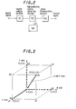
- Fig. 2 is a block diagram showing a schematic structure of a color conversion section according to the first embodiment.
- Fig. 3 is a schematic diagram showing the configuration of representative points in the LUT according to the first embodiment.
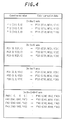
- Fig. 4 is a diagram corresponding to the LUT data according to the first embodiment.
- Figs. 5A and 5B are diagrams explaining the outline of the linear interpolation by means of nearby three points.
- Fig. 6 is a diagram explaining the outline of the linear interpolation on an axis.
- Fig. 7 is a schematic diagram showing the configuration of representative points in the LUT according to the second embodiment.
- Fig. 8 is a diagram corresponding to the LUT data according to the second embodiment.
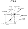
- Fig. 9 is a schematic diagram showing the configuration of representative points in the LUT according to the third embodiment.
- Fig. 10 is a diagram corresponding to the LUT data according to the third embodiment.
- Fig. 11 is a block diagram showing a schematic structure of a color conversion section according to the sixth embodiment.
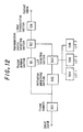
- Fig. 12 is a block diagram showing a schematic structure of a color conversion section according to the seventh embodiment.
- Fig. 13 is a block diagram showing a schematic structure of a color conversion section according to the eighth embodiment.
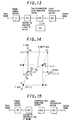
- Fig. 14 is a diagram explaining feet of normal obtained with respect to the nearby axes from the input point in the three-dimensional color space in the 8th embodiment.
- Fig. 15 is a block diagram showing a schematic structure of a color conversion section according to the 9th embodiment.
- Fig. 16 is a block diagram showing a schematic structure of a color conversion section according to the 10th embodiment.
- Fig. 17 is a schematic diagram showing the configuration of representative points in the LUT according to the 10th embodiment.
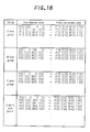
- Fig. 18 is a diagram corresponding to the LUT data according to the 10th embodiment.
- Fig. 19 is a diagram explaining the outline of the linear interpolation on an axis.
- Fig. 20 is a schematic diagram showing the configuration of representative points in the LUT according to the 11th embodiment.
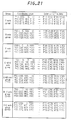
- Fig. 21 is a diagram corresponding to the LUT data according to the 11th embodiment.
- Fig. 22 is a schematic diagram showing the configuration of representative points in the LUT according to the 12th embodiment.
- Fig. 23 is a diagram corresponding to the LUT data according to the 12th embodiment.
- Fig. 24 is a block diagram showing a schematic structure of a color conversion section according to the 13th embodiment.
- Fig. 25 is a schematic diagram showing the configuration of representative points in the LUT according to the 13th embodiment.
- Fig. 26 is a diagram corresponding to the LUT data according to the 13th embodiment.
- Fig. 2 is a block diagram showing a schematic structure of a color conversion processing section according to the first embodiment, which comprises a region judging section 101 for judging in which area the input value resides in the three-dimensional color space, a representative points selecting section 102 for selecting representative points arranged discretely on an axis, respectively, a look-up table (LUT) 103 for storing the coordinates of representative points and color correction data, and a linear interpolation section 104 for performing color conversion by means of weighting based on the selected representative points.
- LUT look-up table
- Fig. 3 schematically shows a configuration of the representative points.
- LUT 103 has color correction data as shown in Fig. 4 with respect to respective representative points, but the number of representative points and the configuration spacing are not limited thereto.
- the color correction data in Fig. 4 is determined according to the properties of devices to which the color conversion of the present invention is applied.
- the three-dimensional color space is divided into three regions depending upon which axis is included therein, when three axes are taken into account in order of propinquity to the input value and the distance among the four axes shown in Fig. 3.
- a region judging section 101 judges that in which region among the above-mentioned regions the input value belongs according to the size relation of the three components of the input value.
- Each region includes three axes among the four axes shown in Fig. 3, and a representative point nearest to the input value is selected from each axis by a representative points selecting section 102. If it is assumed that, as shown in Fig.
- points P1 (C1, M1, Y1), P2 (C2, M2, Y2), and P3 (C3, M3, Y3) are selected as the nearby three points by the representative points selecting section 102, designating the input value as P (C, M, Y), the output value P' (C', M', Y') is given by the following expression: wherein, P'1 (C'1, M'1, Y'1), P'2 (C'2, M'2, Y'2), and P'3 (C'3, M'3, Y'3) represent color correction data of points P1, P2 and P3, respectively, as shown in Fig. 5B.
- the representative points are respectively selected from two axes which are in the vicinity thereof, and the linear interpolation is performed by weighting.
- FIG. 7 The schematic structure of this embodiment is shown in Fig. 2, as in the first embodiment, except that the number of axes for arranging representative points increases.
- the configuration of representative points in this embodiment is shown in Fig. 7.
- the LUT 103 has the color correction data as shown in Fig. 8, with respect to the respective coordinates of the representative points.
- the number of representative points and the configuration spacing are not limited thereto.
- the color correction data in Fig. 8 is determined according to the properties of devices to which the color conversion of the present invention is applied.
- the three-dimensional color space is divided into six regions depending upon which axis is included therein, when three axes are taken into account in order of propinquity to the input value and the distance among the seven axes shown in Fig. 7.
- FIG. 9 The schematic structure of this embodiment is shown in Fig. 2, as in the second embodiment, except that the number of axes for arranging representative points increases.
- the configuration of representative points in this embodiment is shown in Fig. 9.
- the LUT 103 has the color correction data as shown in Fig. 10, with respect to the respective coordinates of the representative points.
- the number of representative points and the configuration spacing are not limited thereto.
- the color correction data in Fig. 10 is to be determined according to the properties of devices to which the color conversion of the present invention is applied.
- the three-dimensional color space is divided into nine regions depending upon which axis is included therein, when three axes are taken into account in order of propinquity to the input value and the distance among the seven axes shown in Fig. 9.
- the region judging section 101 in Fig. 2 judges that in which region among the above-mentioned nine regions the input value belongs, and performs the color conversion processing in the same procedure as in the second embodiment. According to this embodiment, since three axes for arranging representative points in the LUT are added, the accuracy of the color conversion is improved in the portion having high density.
- the fifth embodiment of the present invention will now be described. Since the human eyes are not sensitive to the color difference in an area having a very high density, or in an area having a very low density, the conversion accuracy in these density area may be relatively low. Moreover, in the case of a natural image, the color data distribution in the three-dimensional color space tends to converge on a relatively medium density area. Therefore, by arranging more representative points in the medium density area in the three-dimensional color space, favorable color conversion becomes possible without increasing the memory volume.
- Fig. 11 shows a block diagram of this embodiment, which includes a LUT selecting section 401, as well as LUT1 (402), LUT2 (403) and LUT3 (404) which have different properties.
- the number of LUTs are not limited to 3. Users can adjust the hue of the output image according to their preference, by selecting a LUT using the LUT selecting section 401.
- Fig. 12 shows a block diagram of this embodiment, in which a frame memory 501 and a histogram generating section 502 are newly provided, and further includes LUT1 (504), LUT2 (505) and LUT3 (506) which have different properties.
- the number of LUTs are not limited to 3.
- LUT1 has a high configuration density of representative points in the low density area
- LUT2 has a high configuration density of representative points in the medium density area
- LUT3 has a high configuration density of representative points in the high density area.
- an input image is read into a frame memory 501 and a histogram of the image data is generated by a histogram generating section 502. Based on thus obtained histogram, when there is much distribution in the low density area, LUT1 is selected, when there is much distribution in the medium density area, LUT2 is selected, and when there is much distribution in the high density area, LUT3 is selected. As described above, by automatically selecting the LUT suitable for the input image, more preferable color conversion becomes possible.
- Fig. 13 shows a block diagram of this embodiment.
- a region where the input point exists is decided by a region judging section 101, three axes near the input point are obtained.
- a normal is drawn from the input point to the nearby axis, respectively, as shown in Fig. 14, by a section for searching a foot of normal 601.
- Points H1, H2 and H3 are feet of normal when a normal is drawn from the input point P to the nearby three axes.
- the color correction data at these points H1, H2 and H3 is obtained by dividing the axis at two representative points, respectively, located in the same axes with these points and on both sides of these points, by a new representative points generating section 605.
- the color conversion processing is performed with the same procedure as in the first embodiment by means of the linear interpolation using the data.
- the present invention can generate data nearer to the input point and use the data for the linear interpolation, hence the color conversion with high accuracy becomes possible.
- Fig. 15 shows a block diagram of this embodiment.
- representative points are not discretely arranged on the axis, but a numerical expression is provided for the color correction for every axis. Therefore, no LUT is necessary.
- a region where the input point exists is obtained by the region judging section 101, three axes near the input point are obtained.
- a normal is drawn from the input point to the nearby axis, respectively, as shown in Fig. 14, by a section for searching a foot of normal 601, thus three feet of normal are obtained.
- the color conversion data at the coordinates value at the foot of normal obtained beforehand is obtained by a conversion data generating section 602.
- the color conversion data at three points in the vicinity thereof are obtained, respectively, and by using the data, the color conversion processing is performed with the same procedure as in the first embodiment by means of the linear interpolation.
- the color conversion is not limited to color printers, but can be applied to various input devices and image output devices, for example, in the case of performing the color conversion in scanners and CRT monitors.
- Fig. 16 shows a block diagram showing a schematic structure of a color conversion section according to the 10th embodiment, which comprises a representative points-dispersed axis selecting section 101A which judges in which region in the three-dimensional color space the input value exists and selects a representative points-dispersed axis which becomes the nearby axis in this case; a representative points selecting section 102 for selecting representative points which are in the vicinity of the input value among representative points discretely arranged along respective axes within the selected representative points-dispersed axis; a look-up table (LUT) 103 which stores the coordinates of the representative points and the color correction data, and a linear interpolation section 104 which performs the color conversion by weighting based on the selected representative points.
- LUT look-up table
- Fig. 17 schematically shows the representative points-dispersed axis and the configuration of representative points.
- the three-dimensional color space is a rectangular coordinates system obtained by three axes which designate the origin as a center and are orthogonal to each other, that is, C axis, M axis and Y axis.
- this space is formed a cube composed of apexes having the following coordinates: A0 (0, 0, 0), A1 (100, 0, 0), A2 (100, 100, 0), A3 (0, 100, 0), A4, (0, 0, 100), A5 (100, 0, 100), A6 (100, 100, 100), and A7 (0, 100, 100).
- the C axis passes through each apex A0 - A1
- the M axis passes through each apex A0 - A3
- the Y axis passes through each apex A0 - A4
- the above coordinates are the coordinates component of the C axis, M axis and Y axis in this order.
- a line passing through A0 - A6 is set as an axis.
- the configuration of representative points is an irregular configuration such that in the three-dimensional color space, on a line connecting a certain representative point and the origin, no other representative point exists.
- the LUT 103 has the color correction data as shown in Fig. 18 with respect to respective representative points, but the number and the configuration spacing of representative points are not limited thereto.
- the color correction data of Fig. 18 is to be determined according to the properties of devices to which the color conversion of the present invention is applied.
- the three-dimensional color space is divided into three regions depending upon which axis is included therein, when the axis groups are taken into account in order of propinquity to the input value and the distance among the four axis groups shown in Fig. 17.
- a representative points-dispersed axis selecting section 101A judges that in which region among the above-mentioned three regions the input value belongs according to the size relation of the three components of the input value, and selects three axis groups which are in the vicinity thereof.
- a representative point nearest to the input signal value is selected one each for every axis group, in total three representative points are selected by the representative points selecting section 102.
- the representative points are discretely arranged for each axis group, and the distance between the input point and the representative point is determined for every axis group by means of the least squares, and the representative point having the shortest distance is designated as the nearest point in that axis group.
- the representative points are respectively selected from two axes which are in the vicinity thereof, and the linear interpolation is performed by weighting.
- FIG. 16 The schematic structure of this embodiment is shown in Fig. 16, as in the 10th embodiment, except that the number of axes for arranging representative points in the vicinity of the axis increases.
- the configuration of representative points in this embodiment is shown in Fig. 20.
- Fig. 20 there are added three axis groups for arranging representative points in the vicinity of the axis, as described below, compared to Fig. 17.
- lines passing through A0-A2, A0-A7, A0-A5 are further set as the axis.
- the LUT 103 has the color correction data as shown in Fig. 21, with respect to the respective coordinates of the representative points.
- the number of representative points and the configuration spacing are not limited thereto.
- the color correction data in Fig. 21 is determined according to the properties of devices to which the color conversion of the present invention is applied.
- the three-dimensional color space is divided into six regions depending upon which axis is included therein, when three axes are taken into account in order of propinquity to the input value and the distance among the seven axes shown in Fig. 20.
- the representative points-dispersed axis selecting section 101A in Fig. 16 judges that in which region among the above-mentioned six regions the input value belongs, and when the triangular pyramid belonging thereto is determined, three representative points-dispersed axes to be targeted are determined to select the nearby point.
- the representative points are discretely arranged for each axis group, and the distance between the input point and the representative point is determined for every axis group by means of the least squares, and the representative point having the shortest distance is designated as the nearest point in that axis group.
- the color conversion processing is performed by means of the linear interpolation in the same manner as in the 10th embodiment.
- FIG. 16 The schematic structure of this embodiment is shown in Fig. 16, as in the 10th embodiment, except that the number of axes for arranging representative points are increased.
- the configuration of representative points in this embodiment is shown in Fig. 22.
- Fig. 22 there are added three axes for arranging representative points in the vicinity thereof, compared to Fig. 16.
- lines passing through A6-A2, A6-A7, A6-A5 are further set as an axis.
- the LUT 103 has the color correction data as shown in Fig. 23, with respect to the respective coordinates of the representative points. Moreover, the number of representative points and the configuration spacing are not limited thereto.
- the color correction data in Fig. 23 is determined according to the properties of devices to which the color conversion of the present invention is applied.
- three axes which are in the vicinity of the input value are selected by the representative points nearby axis-selecting section 101A.
- a representative point nearest to the input signal value is selected, respectively, for every axis group, in total three representative points are selected by the representative points selecting section 102.
- the representative points are discretely arranged for each axis group, and the distance between the input point and the representative point is determined for every axis group by means of the least squares, and the representative point having the shortest distance is designated as the nearest point in that axis group.
- the color conversion is performed by means of the linear interpolation in the same manner as in the 10th embodiment.
- the 14th embodiment of the present invention will now be described.
- the human eyes are not so sensitive to the difference of the chroma of colors, hence the conversion accuracy in these brightness regions may be relatively low.
- the color data distribution in the three-dimensional color space tends to converge on a relatively medium brightness area.
- favorable color conversion becomes possible without increasing the memory volume.
- Fig. 24 is a block diagram showing a schematic structure of a color conversion section according to the 10th embodiment, which comprises a nearby plane judging section 201 for judging which three planes among six planes constituting a cube in the three-dimensional color space the input value is close to, a representative points selecting section 202 for selecting a representative point one each in the judged three planes which becomes nearest to the input signal value among representative points arranged discretely on the planes, a look-up table (LUT) 203 for storing the coordinates of representative points and the color correction data, and a linear interpolation section 204 for performing the color conversion by weighting based on the selected representative points.
- LUT look-up table
- Fig. 25 schematically shows the dispersion of representative points.
- representative points are discretely arranged at eight apexes and six planes of the three-dimensional cube.
- the LUT 103 has the color correction data as shown in Fig. 26, but the number of representative points and the configuration spacing are not limited thereto.
- the color correction data in Fig. 26 is to be determined according to the properties of devices to which the color conversion of the present invention is applied.
- a three-dimensional cube is formed, and three planes which are in the vicinity of the input value are selected according to the size relation of three components of the input value among six planes in which representative points are discretely arranged, by the nearby plane-judging section 201.
- the plane from which representative points are to be selected are limited to the above-mentioned three planes.
- a representative point nearest to the input signal value is selected one each for every plane, in total three representative points are selected by the representative points selecting section 202.
- the representative points are discretely arranged on each plane, and the distance between the input point and the representative point is determined for every plane by means of the least squares, and the representative point having the shortest distance is designated as the nearest point in that plane.
- a representative point which becomes nearest to the input point is selected one each, in total three, from respective three planes, and the color conversion value is obtained by means of the linear interpolation using these three points in the same manner as in the 10th embodiment.
- the output value P' is obtained by means of the linear interpolation using the origin and the apex of that axis, in the same manner as in the 10th embodiment.
- the color conversion is not limited to color printers, but can be applied to various input devices and image output devices, for example, in the case of performing the color conversion in scanners and CRT monitors.
- representative points are discretely arranged on respective axes in the three-dimensional color space in advance, and the color conversion can be performed with a necessary minimum LUT.
- the memory capacity can be reduced, and the color conversion with high accuracy can be performed only by 3 ⁇ 3 matrix operation and with a small LUT, hence the effect of reducing the operation volume and the circuit size is quite noticeable.
- the accuracy in the color conversion can be improved.
- the color conversion device of the present invention by arranging the representative points up to the high density area, the accuracy in the color conversion can be improved in the high density area.
- the configuration of representative points can be freely changed, and representative points in the three-dimensional color space can be arranged, taking the human's visual property into account, hence the look-up table can be used effectively.
- the color reproducibility can be improved without increasing the memory capacity.
- users can adjust the hue of the output image according to their preference, by selecting a suitable LUT among a plurality of LUTs.
- the color conversion device of the present invention by selecting a LUT having different conversion property depending upon the input image, the color conversion suitable for the properties of the input image can be performed.
- the color conversion device of the present invention by newly generating the point data nearest to the input point on the axis from the nearby two representative points on the same axis by means of internal division, the color conversion can be performed with high accuracy.
- the color conversion device of the present invention by setting a numerical expression for the color correction instead of the LUT, it is possible not having a memory for the LUT data.
- the color conversion device of the present invention by irregularly arranging representative points which store the color correction data in the vicinity of axes in the three-dimensional color space, discontinuity in the color conversion can be eliminated, and the color conversion can be performed with only a necessary minimum LUT, hence reduction of the operation volume and the memory capacity becomes possible.
- the color conversion device of the present invention by adding three axes in which representative points in the LUT are arranged in the vinicity of a nearby axis, representative points are arranged up to the low brightness area, hence the accuracy in the color conversion can be improved in the low brightness area.
- the color conversion device of the present invention by arranging more representative points in the medium brightness area, the color producibility can be improved without increasing the memory capacity.
- the color conversion device of the present invention by arranging representative points on a plane, the freedom of configuration of representative points increases, and representative points in the three-dimensional color space can be arranged, taking the human's visual property into account, hence reduction of the operation volume and the memory capacity used for the search of nearby points can be realized, representative points used as a LUT can be easily set, and the look-up table can be used effectively.
Landscapes
- Engineering & Computer Science (AREA)
- Multimedia (AREA)
- Signal Processing (AREA)
- Color Image Communication Systems (AREA)
- Facsimile Image Signal Circuits (AREA)
- Image Processing (AREA)
Applications Claiming Priority (6)
| Application Number | Priority Date | Filing Date | Title |
|---|---|---|---|
| JP7252497 | 1997-03-26 | ||
| JP07252497A JP3664836B2 (ja) | 1997-03-26 | 1997-03-26 | 色変換方法 |
| JP72524/97 | 1997-03-26 | ||
| JP2303698 | 1998-02-04 | ||
| JP02303698A JP3614291B2 (ja) | 1998-02-04 | 1998-02-04 | 色変換装置 |
| JP23036/98 | 1998-02-04 |
Publications (3)
| Publication Number | Publication Date |
|---|---|
| EP0868075A2 true EP0868075A2 (fr) | 1998-09-30 |
| EP0868075A3 EP0868075A3 (fr) | 2000-03-15 |
| EP0868075B1 EP0868075B1 (fr) | 2004-10-27 |
Family
ID=26360329
Family Applications (1)
| Application Number | Title | Priority Date | Filing Date |
|---|---|---|---|
| EP98302302A Expired - Lifetime EP0868075B1 (fr) | 1997-03-26 | 1998-03-26 | Dispositif de conversion de couleurs |
Country Status (3)
| Country | Link |
|---|---|
| US (1) | US6118549A (fr) |
| EP (1) | EP0868075B1 (fr) |
| DE (1) | DE69827183T2 (fr) |
Cited By (5)
| Publication number | Priority date | Publication date | Assignee | Title |
|---|---|---|---|---|
| EP1315366A1 (fr) * | 2001-11-26 | 2003-05-28 | Agfa-Gevaert | Procédé de séparation de couleur |
| EP1326427A1 (fr) * | 2001-12-25 | 2003-07-09 | Ricoh Company, Ltd. | Appareil et procédé de formation d'images en couleur |
| EP1349373A3 (fr) * | 2002-03-20 | 2006-10-11 | Seiko Epson Corporation | Procédé pour la correction de données d'images selon une table de correction |
| US7265870B2 (en) | 2001-11-26 | 2007-09-04 | Agfa Graphics Nv | Colour separation method |
| CN111770320A (zh) * | 2020-07-14 | 2020-10-13 | 深圳市洲明科技股份有限公司 | 一种色彩校正方法和装置、色彩校正设备和存储介质 |
Families Citing this family (11)
| Publication number | Priority date | Publication date | Assignee | Title |
|---|---|---|---|---|
| JP3912903B2 (ja) * | 1998-07-02 | 2007-05-09 | キヤノン株式会社 | データ変換方法およびその装置 |
| JP2001111858A (ja) * | 1999-08-03 | 2001-04-20 | Fuji Photo Film Co Ltd | 色修正定義作成方法、色修正定義作成装置、および色修正定義作成プログラム記憶媒体 |
| JP2002118752A (ja) * | 2000-10-05 | 2002-04-19 | Sony Corp | 画像処理装置および方法、並びに記録媒体 |
| US7190487B2 (en) * | 2001-09-25 | 2007-03-13 | Sharp Laboratories Of America, Inc. | Color conversion with hue straightening using multiple look-up tables and interpolation |
| TW559737B (en) * | 2001-11-02 | 2003-11-01 | Ind Tech Res Inst | Color conversion method for preference color |
| US7233695B2 (en) * | 2002-07-01 | 2007-06-19 | Xerox Corporation | Scan color conversion method |
| US7430318B2 (en) * | 2004-07-13 | 2008-09-30 | Toshiba Corporation | System and method for color correction for electronic printing |
| JP2007134750A (ja) * | 2005-10-12 | 2007-05-31 | Seiko Epson Corp | 色変換装置、色変換方法、色変換プログラム、画像処理装置、及び画像表示装置 |
| US7921146B2 (en) * | 2005-11-01 | 2011-04-05 | Infoprint Solutions Company, Llc | Apparatus, system, and method for interpolating high-dimensional, non-linear data |
| US8046200B2 (en) | 2006-09-05 | 2011-10-25 | Colorado State University Research Foundation | Nonlinear function approximation over high-dimensional domains |
| US8593708B2 (en) * | 2010-03-15 | 2013-11-26 | Xerox Corporation | Methods, systems and apparatus for jointly optimizing node locations and corresponding output values of a color look-up-table (LUT) |
Citations (1)
| Publication number | Priority date | Publication date | Assignee | Title |
|---|---|---|---|---|
| JPS63162248A (ja) | 1986-12-25 | 1988-07-05 | Konica Corp | 色分解画像修正方法及び装置 |
Family Cites Families (9)
| Publication number | Priority date | Publication date | Assignee | Title |
|---|---|---|---|---|
| US4929978A (en) * | 1987-10-23 | 1990-05-29 | Matsushita Electric Industrial Co., Ltd. | Color correction method for color copier utilizing correction table derived from printed color samples |
| JP3008472B2 (ja) * | 1990-10-05 | 2000-02-14 | ブラザー工業株式会社 | カラー画像処理装置 |
| JPH04156779A (ja) * | 1990-10-19 | 1992-05-29 | Matsushita Electric Ind Co Ltd | 色変換装置 |
| US5311332A (en) * | 1990-12-20 | 1994-05-10 | Ricoh Company, Ltd. | Interpolation method and color correction method using interpolation |
| BE1004659A5 (nl) * | 1991-03-01 | 1993-01-05 | Barco Graphics Nv | Werkwijze en inrichting voor het transformeren van een kleurcoordinatenset. |
| US5307182A (en) * | 1991-12-30 | 1994-04-26 | Xerox Corporation | Methods and apparatus for multigeneration color image processing |
| JPH07170421A (ja) * | 1993-09-27 | 1995-07-04 | Ricoh Co Ltd | 色変換方法 |
| US5627950A (en) * | 1994-09-16 | 1997-05-06 | Apple Computer, Inc. | Real-time three-dimensional color look-up table interactive editor system and method |
| US5644509A (en) * | 1994-10-07 | 1997-07-01 | Eastman Kodak Company | Method and apparatus for computing color transformation tables |
-
1998
- 1998-03-19 US US09/044,261 patent/US6118549A/en not_active Expired - Lifetime
- 1998-03-26 EP EP98302302A patent/EP0868075B1/fr not_active Expired - Lifetime
- 1998-03-26 DE DE69827183T patent/DE69827183T2/de not_active Expired - Lifetime
Patent Citations (1)
| Publication number | Priority date | Publication date | Assignee | Title |
|---|---|---|---|---|
| JPS63162248A (ja) | 1986-12-25 | 1988-07-05 | Konica Corp | 色分解画像修正方法及び装置 |
Non-Patent Citations (1)
| Title |
|---|
| PATENT ABSTRACTS OF JAPAN |
Cited By (7)
| Publication number | Priority date | Publication date | Assignee | Title |
|---|---|---|---|---|
| EP1315366A1 (fr) * | 2001-11-26 | 2003-05-28 | Agfa-Gevaert | Procédé de séparation de couleur |
| US7265870B2 (en) | 2001-11-26 | 2007-09-04 | Agfa Graphics Nv | Colour separation method |
| EP1326427A1 (fr) * | 2001-12-25 | 2003-07-09 | Ricoh Company, Ltd. | Appareil et procédé de formation d'images en couleur |
| US7286262B2 (en) | 2001-12-25 | 2007-10-23 | Ricoh Company, Ltd. | Image formation apparatus and method, and computer product |
| EP1349373A3 (fr) * | 2002-03-20 | 2006-10-11 | Seiko Epson Corporation | Procédé pour la correction de données d'images selon une table de correction |
| US7336392B2 (en) | 2002-03-20 | 2008-02-26 | Seiko Epson Corporation | Method of correcting color image data according to correction table |
| CN111770320A (zh) * | 2020-07-14 | 2020-10-13 | 深圳市洲明科技股份有限公司 | 一种色彩校正方法和装置、色彩校正设备和存储介质 |
Also Published As
| Publication number | Publication date |
|---|---|
| US6118549A (en) | 2000-09-12 |
| DE69827183T2 (de) | 2005-11-03 |
| EP0868075A3 (fr) | 2000-03-15 |
| EP0868075B1 (fr) | 2004-10-27 |
| DE69827183D1 (de) | 2004-12-02 |
Similar Documents
| Publication | Publication Date | Title |
|---|---|---|
| US6118549A (en) | Color conversion device | |
| EP0679019B1 (fr) | Appareil et procédé de traitement d'images | |
| US7706036B2 (en) | Color conversion program, apparatus, and method enabling high precision color conversion | |
| US7333237B2 (en) | Color adjustment method, color adjustment apparatus, color conversion definition editing apparatus, image processing apparatus, program, and storage medium | |
| US6650772B1 (en) | Image processing apparatus, image processing method, and image processing system | |
| EP0611231B1 (fr) | Procédé de calibrage et amélioration de couleur entre des dispositifs utilisant des contraintes explicites | |
| JP3737149B2 (ja) | カラー・イメージ生成システムおよび方法 | |
| US6546132B1 (en) | Color table manipulations for smooth splicing | |
| US8164597B2 (en) | Color conversion circuit and method of color conversion using interpolation from conversion coefficients some of which are substituted | |
| JP3976849B2 (ja) | 補間器入力データを生成する装置 | |
| EP0457427B1 (fr) | Appareil pour améliorer la netteté d'une image en couleur | |
| US6862111B2 (en) | Method and apparatus for quantizing a color image through a single dither matrix | |
| US5497249A (en) | Image data processing apparatus with selective processing filters | |
| Lo et al. | Colour quantization by three-dimensional frequency diffusion | |
| US5365252A (en) | Color quantization apparatus and method for frame buffer display | |
| JP4338940B2 (ja) | Ymckインクおよび追加の色インクが用いられるプログラム | |
| JP4112413B2 (ja) | 画像処理装置、画像形成装置、画像処理方法、画像処理プログラム、及び画像処理プログラムを記録したコンピュータ読み取り可能な記録媒体 | |
| JP4197900B2 (ja) | パレット色の組を用いてディジタルカラー画像を表現する方法 | |
| MacDonald et al. | A topographic gamut compression algorithm | |
| JP2010050832A (ja) | 画像処理装置、画像処理方法、プログラムおよび記録媒体 | |
| JP2006115500A (ja) | 高速低メモリ紙色抑制アルゴリズム | |
| JP4307058B2 (ja) | 画像処理方法及び画像処理装置 | |
| JPH0993445A (ja) | 画像処理装置 | |
| JP3664836B2 (ja) | 色変換方法 | |
| JP3614291B2 (ja) | 色変換装置 |
Legal Events
| Date | Code | Title | Description |
|---|---|---|---|
| PUAI | Public reference made under article 153(3) epc to a published international application that has entered the european phase |
Free format text: ORIGINAL CODE: 0009012 |
|
| AK | Designated contracting states |
Kind code of ref document: A2 Designated state(s): DE FR GB |
|
| AX | Request for extension of the european patent |
Free format text: AL;LT;LV;MK;RO;SI |
|
| PUAL | Search report despatched |
Free format text: ORIGINAL CODE: 0009013 |
|
| AK | Designated contracting states |
Kind code of ref document: A3 Designated state(s): AT BE CH DE DK ES FI FR GB GR IE IT LI LU MC NL PT SE |
|
| AX | Request for extension of the european patent |
Free format text: AL;LT;LV;MK;RO;SI |
|
| 17P | Request for examination filed |
Effective date: 20000517 |
|
| AKX | Designation fees paid |
Free format text: DE FR GB |
|
| 17Q | First examination report despatched |
Effective date: 20010411 |
|
| GRAP | Despatch of communication of intention to grant a patent |
Free format text: ORIGINAL CODE: EPIDOSNIGR1 |
|
| GRAS | Grant fee paid |
Free format text: ORIGINAL CODE: EPIDOSNIGR3 |
|
| GRAA | (expected) grant |
Free format text: ORIGINAL CODE: 0009210 |
|
| AK | Designated contracting states |
Kind code of ref document: B1 Designated state(s): DE FR GB |
|
| REG | Reference to a national code |
Ref country code: GB Ref legal event code: FG4D |
|
| REF | Corresponds to: |
Ref document number: 69827183 Country of ref document: DE Date of ref document: 20041202 Kind code of ref document: P |
|
| ET | Fr: translation filed | ||
| PLBE | No opposition filed within time limit |
Free format text: ORIGINAL CODE: 0009261 |
|
| STAA | Information on the status of an ep patent application or granted ep patent |
Free format text: STATUS: NO OPPOSITION FILED WITHIN TIME LIMIT |
|
| 26N | No opposition filed |
Effective date: 20050728 |
|
| PGFP | Annual fee paid to national office [announced via postgrant information from national office to epo] |
Ref country code: FR Payment date: 20110317 Year of fee payment: 14 |
|
| PGFP | Annual fee paid to national office [announced via postgrant information from national office to epo] |
Ref country code: GB Payment date: 20110323 Year of fee payment: 14 Ref country code: DE Payment date: 20110323 Year of fee payment: 14 |
|
| GBPC | Gb: european patent ceased through non-payment of renewal fee |
Effective date: 20120326 |
|
| REG | Reference to a national code |
Ref country code: FR Ref legal event code: ST Effective date: 20121130 |
|
| REG | Reference to a national code |
Ref country code: DE Ref legal event code: R119 Ref document number: 69827183 Country of ref document: DE Effective date: 20121002 |
|
| PG25 | Lapsed in a contracting state [announced via postgrant information from national office to epo] |
Ref country code: FR Free format text: LAPSE BECAUSE OF NON-PAYMENT OF DUE FEES Effective date: 20120402 Ref country code: GB Free format text: LAPSE BECAUSE OF NON-PAYMENT OF DUE FEES Effective date: 20120326 |
|
| PG25 | Lapsed in a contracting state [announced via postgrant information from national office to epo] |
Ref country code: DE Free format text: LAPSE BECAUSE OF NON-PAYMENT OF DUE FEES Effective date: 20121002 |