EP0868107A2 - Unité de haut-parleur - Google Patents
Unité de haut-parleur Download PDFInfo
- Publication number
- EP0868107A2 EP0868107A2 EP98105205A EP98105205A EP0868107A2 EP 0868107 A2 EP0868107 A2 EP 0868107A2 EP 98105205 A EP98105205 A EP 98105205A EP 98105205 A EP98105205 A EP 98105205A EP 0868107 A2 EP0868107 A2 EP 0868107A2
- Authority
- EP
- European Patent Office
- Prior art keywords
- loudspeaker
- directivity
- sound pressure
- driven
- box
- Prior art date
- Legal status (The legal status is an assumption and is not a legal conclusion. Google has not performed a legal analysis and makes no representation as to the accuracy of the status listed.)
- Withdrawn
Links
Images




Classifications
-
- H—ELECTRICITY
- H04—ELECTRIC COMMUNICATION TECHNIQUE
- H04R—LOUDSPEAKERS, MICROPHONES, GRAMOPHONE PICK-UPS OR LIKE ACOUSTIC ELECTROMECHANICAL TRANSDUCERS; ELECTRIC HEARING AIDS; PUBLIC ADDRESS SYSTEMS
- H04R1/00—Details of transducers, loudspeakers or microphones
- H04R1/20—Arrangements for obtaining desired frequency or directional characteristics
- H04R1/22—Arrangements for obtaining desired frequency or directional characteristics for obtaining desired frequency characteristic only
- H04R1/227—Arrangements for obtaining desired frequency or directional characteristics for obtaining desired frequency characteristic only using transducers reproducing the same frequency band
-
- H—ELECTRICITY
- H04—ELECTRIC COMMUNICATION TECHNIQUE
- H04R—LOUDSPEAKERS, MICROPHONES, GRAMOPHONE PICK-UPS OR LIKE ACOUSTIC ELECTROMECHANICAL TRANSDUCERS; ELECTRIC HEARING AIDS; PUBLIC ADDRESS SYSTEMS
- H04R1/00—Details of transducers, loudspeakers or microphones
- H04R1/02—Casings; Cabinets ; Supports therefor; Mountings therein
Definitions
- the present invention relates to a directional loudspeaker unit. More specifically, the present invention relates to a loudspeaker unit intended to realize directivity suitable for enlarging a region of satisfactory stereophonic listening position by attaching a first loudspeaker driven in a positive polarity to a front panel of a loudspeaker box, attaching a second loudspeaker driven in a negative polarity to, for example, an upper panel of the loudspeaker box, and driving the first and the second loudspeaker so that the radiation sound pressure of the second loudspeaker is lower than that of the first loudspeaker.
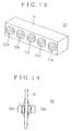
- FIG. 13 shows a Tonchulen directional loudspeaker unit 20 by way of example.
- the loudspeaker unit 20 has a plurality of loudspeakers, i.e., five loudspeakers 22a to 22e, linearly arranged on a panel of a loudspeaker box 21.
- the loudspeaker unit 20 provided with the laterally arranged plurality of loudspeakers has a sharp directivity in a horizontal plane.
- FIG. 14 shows a bidirectional loudspeaker unit 30.
- This loudspeaker unit 30 is assembled by attaching two loudspeakers 32a and 32b to the front and the back surface of a baffle plate 31 opposite to each other.
- the two loudspeakers 32a and 32b are driven respectively in opposite polarities.
- a loudspeaker unit according to the present invention which will be explained later, is different in construction and directivity from the foregoing conventional directional loudspeaker units.
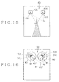
- a conventional two-channel stereophonic loudspeaker unit 40 has a right loudspeaker 41R attached to a front panel of a loudspeaker box 42R, and a left loudspeaker 41L attached to a front panel of a loudspeaker box 42L.
- the loudspeaker boxes 42R and 42L are disposed with their front panels facing a listener situated in front of the loudspeaker unit 40.
- listening positions suitable for satisfactorily listening to stereophonic sounds are limited to those in a very narrow region including a point a on a center line bisecting a line connecting the loudspeakers 41R and 41L as indicated by a shaded region in FIG. 15.
- a conventional two-channel stereophonic sound reproducing method intended to enlarge a range for listening positions where satisfactory stereophonic listening is possible utilizes the directivity of loudspeakers.
- a two-channel stereophonic loudspeaker unit 50 shown in FIG. 16 is provided with a right loudspeaker 51R and a left loudspeaker 51L attached to closed cabinets 52R and 52L with their reference axes directed inward at an angle of about 45° with respect to a center listening position to use directivity dependent on the diameters of the loudspeakers, and the dimensions and shapes of the cabinets.
- This loudspeaker unit is intended to enlarge a region for listening positions where stereophonic sounds can be satisfactorily heard by the corrective agency of the directivities of the loudspeakers to reduce the difference between the respective levels of an R signal sound and an L signal sound attributable to the difference between distances from a listening position b dislocated from the center line to the loudspeakers.
- directivity of a loudspeaker is dependent on the diameter of the loudspeaker, and the shape and dimensions of the cabinet, and a loudspeaker of a smaller diameter becomes directional for sounds of higher frequencies and becomes substantially non-directional for sounds of middle and low frequencies.
- Directivity for sounds of frequencies not higher than 1 KHz affects greatly appropriate listening region enlarging effect.
- a curve w1 indicates a directivity pattern for sounds of middle and high frequencies
- a curve w2 indicates a directivity pattern for sounds of middle and low frequencies
- a indicates, similarly to a in FIG. 15, a point on the center line bisecting a line connecting the right and the left loudspeaker.
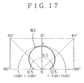
- Directivity capable of enlarging a region for listening points must decrease sound pressure with the increase of the angle of a direction to the reference axis of the loudspeaker from 0° toward 90° as indicated by a curve w3 in FIG. 17, and it is desirable that the sound pressure with respect to a 90°-direction is lower than that with respect to a 0°-direction by 6 dB or above.
- a loudspeaker unit characterized in that a first loudspeaker is attached to a front panel of the loudspeaker box as installed, a second loudspeaker is attached to an upper panel, a lower panel or a back panel of the loudspeaker box as installed, the first loudspeaker is driven in a positive polarity and the second speaker is driven in a negative polarity, and the radiation sound pressure of the second loudspeaker is lower than that of the first loudspeaker.
- the directivity factor in terms of the synthesis sound pressure of the first and the second loudspeaker at a sound receiving position in the 90°-direction is equal to the product of the directivity factor D(90°) of each loudspeaker and (1 - ⁇ ) ⁇ 1. That is, in the 90°-direction, the output sound pressure of the loudspeaker can be reduced regardless of frequency.
- the output sound pressure reduction ratio increases from 0° toward 90°, reaches a maximum of (1 - ⁇ ) at 90°, and decreases from 90° toward 180°.
- FIG. 1 shows a loudspeaker unit 10 in a preferred embodiment according to the present invention.
- a first loudspeaker SP1 is attached to a front panel (front wall) 11F of a loudspeaker box 11 having the shape of a rectangular prism as installed.
- a second loudspeaker SP2 of the same diameter as that of the first loudspeaker SP1 is attached to an upper panel 11U of the loudspeaker box 11.
- the loudspeaker SP2 is disposed so that its reference axis L2 intersects the reference axis L1 of the loudspeaker SP1.
- the loudspeaker SP1 is driven in a positive polarity, and the loudspeaker SP2 is driven in a negative polarity.
- Driving voltages E1 and -E2 respectively for driving the loudspeakers SP1 and SP2 are optional voltages meeting: E2/E1 ⁇ 1. Since the loudspeakers SP1 and SP2 are the same in diameter, the radiation sound pressure of the loudspeaker SP2 is lower than that of the loudspeaker SP1.
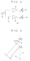
- FIG. 3 shows a driving circuit 13 for driving the loudspeakers SP1 and SP2.
- An amplifier 16 amplifies an output speech signal SA provided by a signal source 15 and gives an amplified speech signal to the loudspeaker SP1.
- the loudspeaker SP1 is driven by the driving voltage E1 in a positive polarity.
- An attenuator 17 attenuates the output speech signal SA provided by the signal source 15, and an amplifier 18 amplifies and inverts the output of the attenuator 17 and gives its output to the loudspeaker SP2.
- the loudspeaker SP2 is driven by the driving voltage -E2 (E2 ⁇ E1) in a negative polarity.
- a method of driving the loudspeaker SP2 by a driving power lower than that for driving the loudspeaker SP1 provides the loudspeaker SP2 with a voice coil of a resistance higher than that of a voice coil for the loudspeaker SP1.
- a current which flows through the voice coil of the loudspeaker SP2 is smaller than that which flows through the voice coil of the loudspeaker SP1, and hence driving power for driving the loudspeaker SP2 is lower than that for driving the loudspeaker SP1.
- This method is advantageous in using one amplifier for the parallel driving of the two loudspeakers.
- V 1 V 0 1+ 1+ F 2
- V0 is expressed in Equation (2).
- s0 is the equivalent stiffness of the diaphragm
- m0 is the effective mass of the diaphragm
- r0 is equivalent mechanical resistance including electromagnetic damping resistance
- s1 is the equivalent stiffness of air in the box
- ⁇ 0 a minimum resonance angular frequency dependent on m0 and s0
- Q0 is the Q factor of the resonance of the diaphragm.
- V 0 F 1 s 0+2 s 1 ( j ⁇ ) 2 m 0 + r 0 j ⁇ m 0 +1
- V 2 - V 0 F 2 F 1 + 1+ F 2 F 1 s 1 s 0 ⁇ 1 1- ⁇ ⁇ 0 2 + j ⁇ ⁇ 0 Q 0
- the second terms in brackets of Equations (1) and (3) express the effect of the mutual influence of the two loudspeakers jointly using a single air chamber and can be handled as follows.
- the second term in brackets has a second-order LPF (low-pass filter) characteristic and its cutoff frequency f0 is equal to the lowest resonance frequency of the diaphragm of the loudspeaker.
- the cutoff frequency f0 can be set at a low frequency not higher than 200 Hz, and a condition: s1/s0 « 1 can be very easily satisfied by properly determining the volume of the box.
- the second term in brackets is very small as compared with the first term in brackets and may be omitted if the loudspeaker unit is intended to be capable of dealing with sounds of frequencies not lower than about 200 Hz.
- V1 and V2 can be expressed by Equations (4) and (5).
- V1 V0
- V2 -V0(F2/F1)
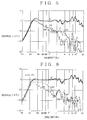
- FIG. 4 An idea illustrated in FIG. 4 is applied to the theoretical examination of the synthesis sound pressure of sound waves radiated by the loudspeaker SP1 and SP2.
- the distance between a plane including the front surface of the loudspeaker SP1 and the reference axis of the loudspeaker SP2 is indicated at d and, in discussing components of sound waves radiated by the loudspeaker SP1 and SP2 with respect to a direction in a horizontal plane, a direction parallel to the reference axis L1 of the loudspeaker SP1 is called a 0°-direction, and the angle ⁇ between a direction and the reference axis L1 is measured clockwise.
- a sound wave at a receiving position may be regarded as a plane wave if the sound receiving position is at a distance r from the loudspeaker. Since the diaphragm of the loudspeaker has a finite area, the directivity of a sound wave radiated from the surface of the diaphragm is dependent on the dimensions and shape of the box, and the dependence of the directivity of a sound wave on the diameter of the loudspeaker increases as the frequency of the sound wave increases, and the greater the diameter of the loudspeaker, the lower is the frequency of the sound wave at which the sound wave becomes directional.
- Equation (6) sound pressure P1( ⁇ ) of a sound wave radiated by the loudspeaker SP1 is expressed by Equation (6), in which S indicates the effective area of the diaphragm, ⁇ is the density of air and c is sound velocity.
- P 1( ⁇ ) j ⁇ SV 0 4 ⁇ r ⁇ D ( ⁇ ) ⁇ e -j ⁇ r c
- Sound pressure P2( ⁇ ) at the sound receiving position is delayed behind the sound pressure P1( ⁇ ) by dcos ⁇ , and the loudspeaker SP2 is driven by a negative voltage -E2 which is different from that in the loudspeaker SP1. Therefore, the sound pressure P2( ⁇ ) of the sound wave radiated by the loudspeaker SP2 is expressed by Equation (7), in which -V2 is the vibrating velocity of the diaphragm.
- P 2( ⁇ ) - j ⁇ SV 0( F 2/ F 1) 4 ⁇ r D (90°) ⁇ e - j ⁇ r c ⁇ e - j ⁇ d c cos ⁇
- P( ⁇ ) Since synthesis sound pressure P( ⁇ ) is equal to P1( ⁇ ) + P2( ⁇ ), P( ⁇ ) is expressed by Equation (8).
- P ( ⁇ ) j ⁇ SV 0 4 ⁇ r e - j ⁇ r c ⁇ D ( ⁇ )- F 2 F 1 ⁇ D (90°) ⁇ e - j ⁇ d c cos ⁇
- Equation (9) is obtained by rearranging Equation (8).
- P ( ⁇ ) j ⁇ SV 0 4 ⁇ r e - j ⁇ r c ⁇ D ( ⁇ )- ⁇ D (90°) ⁇ e - j ⁇ d c cos ⁇
- P 0 j ⁇ SV 0 4 ⁇ r e - j ⁇ r c
- P ( ⁇ ) P 0 D ( ⁇ )- ⁇ D (90°) ⁇ e - j ⁇ d c cos ⁇
- Equation (11) expresses the directivity factor of the synthesis sound pressure at the sound receiving position. Equation (12) is obtained by substituting ⁇ /c by k and introducing trigonometric functions into Equation (11).
- P ( ⁇ ) P 0 D ( ⁇ )- ⁇ D (90°)cos( kd cos ⁇ )+ j ⁇ D (90°)sin( kd cos ⁇ )
- Directivity of a loudspeaker is dependent on the diameter of the loudspeaker, and the shape and dimensions of the box, and the loudspeaker becomes non-directional for sounds of low frequencies. Therefore, for sounds of low frequencies, D(0°) ⁇ D(90°) ⁇ D(180°) ⁇ 1. For low-frequency sounds which meet kd « 1, cos kd ⁇ 1 , sin kd ⁇ kd , and kd may be neglected.
- P(0°)/P0, P(90°)/P0 and P(180°)/P0 expressed respectively by Equations (13), (14) and (15) are equal to (1 - ⁇ ); that is, for sounds of low frequencies, directivity of a loudspeaker with synthesis sound pressure is (1 - ⁇ ) and the loudspeaker is non-directional.
- Directivity of a loudspeaker which is dependent on the diameter of the loudspeaker, and the shape and dimensions of the box, becomes manifest for sounds of high frequencies, and directivity is sharper for sounds of higher frequencies.
- the directivity of the loudspeaker unit 10 shown in FIG. 1 is characterized by the possibility of reducing the output sound pressure of the loudspeaker with respect to the 90°-direction regardless of frequency because the directivity factor with respect to the 90°-direction can be obtained by multiplying the directivity factor D(90°) of the loudspeaker by (1 - ⁇ ) ( ⁇ 1) as expressed by Equation (14).
- the reduction of the output sound pressure does not occur only in the 90°-direction.
- the sound pressure reduction ratio with respect to direction increases as the angle of direction increases from 0° toward 90°, reaches a maximum of (1 - ⁇ ) at an angle of 90°, and decreases as the angle increases from 90° toward 180°.
- the output sound pressure characteristic and directivity of the loudspeaker unit 10 will be more specifically described on the basis of results of experiments.
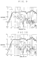
- FIG. 5 is a graph showing the frequency characteristics of output sound pressure directivity for the 0°-direction, the 90°-direction and the 180°-direction measured in an anechoic room when only the loudspeaker SP1 is driven.
- the loudspeaker SP1 is substantially non-directional for sounds of frequencies not higher than about 300 Hz.
- the output sound pressure characteristic with respect to the 90°-direction and the 180°-direction for sounds of frequencies not lower than 300 Hz decreases, on the average, at a rate of about -6 dB/oct as frequency increases, which indicates that the sharpness of directivity increases as frequency increases for sounds of frequencies not lower than 300 Hz.
- FIGS. 6 and 7 show measured directivity patterns of the loudspeaker SP1 for frequencies of 200 Hz, 500 Hz, 1 KHz, 2 KHz, 5 KHz and 10 KHz. As is obvious from FIGS. 6 and 7, the directivity is sharper for higher frequencies.
- the loudspeaker SP1 is substantially non-directional for sounds of low frequencies lower than 500 Hz, and the reduction of sound pressure with respect to the 90°-direction as compared with the sound pressure with respect to the 0°-direction is excessively small, which is an undesirable directivity in effect on the enlargement of a region for satisfactory stereophonic listening positions.
- FIGS. 8, 9 and 10 show measured frequency characteristic of output sound pressure directivity with respect to the 0°-direction, the 90°-direction and the 180°-direction for values of ⁇ of 0.316 (-10 dB), 0.5 (-6 dB) and 0.708 (-3 dB).
- the loudspeaker unit is substantially non-directional for frequencies not higher than about 200 Hz.
- the sound pressure characteristic with respect to the 180°-direction has peaks and dips and is higher on the average than that when only the loudspeaker SP1 is driven. However, since sound waves propagating in the 180°-direction are those propagating behind the loudspeaker unit 10 and have no direct effect on the enlargement of the region for satisfactory stereophonic listening position.
- the sound pressure characteristic with respect to the 0°-direction as compared with that when only the loudspeaker SP1 is driven, is scarcely dependent on frequency and the lower limit of the reproducing band is narrowed slightly.
- the sound pressure with respect to the 0°-direction is slightly higher than that with respect to the 90°-direction, and the sound pressure with respect to the 180°-direction is slightly lower than that with respect to the 90°-direction for frequencies not higher than 200 Hz.
- Such a tendency grows as the value of ⁇ approaches 1.
- This phenomenon is dependent on the distance between the loudspeaker and sound receiving position and can be explained on the basis of the following reasons.
- the loudspeaker becomes non-directional for sounds of lower frequencies, provided that the distance d between a plane including the front end of the loudspeaker SP1 and the reference axis of the loudspeaker SP2 is negligibly small as compared with the distance r between the loudspeaker SP1 and the sound receiving position.
- the distance d is 10 cm while the distance r is 100 cm. Therefore, the distance between the loudspeaker SP2 and the sound receiving position in the 0°-direction is 110 cm and is 90 cm in the 180°-direction.
- the distance between the loudspeaker SP1 and the sound receiving position and the distance between the loudspeaker SP2 and the sound receiving position are 100 cm and 110 cm in the 0°-direction, respectively, and 100 cm and 90 cm in the 180°-direction, respectively.
- the difference in sound pressure due to the difference of 10% in distance brings about the foregoing phenomenon.
- the difference of only 10% in distance causes such a phenomenon because the synthesis sound pressure at the sound receiving position is not the sum of the vectors of the sound waves radiated by the loudspeakers SP1 and SP2 but the same is the difference between the vectors, which is entirely the same as the proximity effect specific to a bidirectional or unidirectional microphone. Such proximity effect is more significant when the sound receiving position is nearer to a sound source.
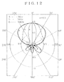
- FIGS. 11 and 12 show directivity patterns corresponding to those shown in FIGS. 6 and 7 when only the loudspeaker SP1 is driven.
- ⁇ 0.5.
- the directivity factor of the directivity pattern for frequencies not lower than 2 KHz shown in FIG. 12 with respect to the 90°-direction is smaller than that of the directivity pattern shown in FIG. 7.
- the general directivity pattern shown in FIG. 12 and that shown in FIG. 7 are substantially the same.
- the directivity is considerably sharp for frequencies not lower than 2 KHz even if only the loudspeaker SP1 is driven. Therefore, a directivity effective in enlarging the region for stereophonic listening positions can be realized by driving only the loudspeaker SP1.
- the directivity factor of the directivity pattern with respect to the 90°-direction for frequencies not higher than 1 KHz shown in FIG. 11 is half that of the directivity pattern shown in FIG. 6, and hence the directivity pattern has a constricted part. Therefore, the loudspeaker unit 10 shown in FIG. 1 has a directivity suitable for enlarging a region for stereophonic listening positions.
- the loudspeaker SP2 of the loudspeaker unit 10 in the foregoing embodiment is attached to the upper panel 11U of the loudspeaker box 11 as installed, the loudspeaker SP2 may be attached to the lower panel or the back panel of the loudspeaker box 11.
- the loudspeaker SP1 and SP2 employed in the foregoing embodiment have the same diameter, the loudspeaker unit 10 may be provided with loudspeakers respectively having different diameters. Even if the loudspeakers SP1 and SP2 are those respectively having different diameters, the sound pressure of sounds radiated by the loudspeaker SP2 must be lower than that of sounds radiated by the loudspeaker SP1.
- the first loudspeaker driven in a positive polarity is attached to the front panel of the loudspeaker box
- the second loudspeaker driven in a negative polarity is attached to, for example, the upper panel of the loudspeaker box
- the sound pressure of sounds radiated by the second loudspeaker is lower than that of sounds radiated by the first loudspeaker
- the directivity factor of the synthesis sound pressure of the first and the second loudspeaker at a sound receiving position with respect to the 90°-direction is equal to the product of the directivity factor of the loudspeaker and a value smaller than one.
- the directivity makes the sound pressure with respect to the 90°-direction lower than that with respect to the 0°-direction (forward direction) for frequencies not higher than 1 KHz by 6 dB or above, so that the directivity is suitable for enlarging the region for satisfactory stereophonic listening positions.
Landscapes
- Physics & Mathematics (AREA)
- Engineering & Computer Science (AREA)
- Acoustics & Sound (AREA)
- Signal Processing (AREA)
- Health & Medical Sciences (AREA)
- Otolaryngology (AREA)
- Obtaining Desirable Characteristics In Audible-Bandwidth Transducers (AREA)
- Circuit For Audible Band Transducer (AREA)
Applications Claiming Priority (3)
| Application Number | Priority Date | Filing Date | Title |
|---|---|---|---|
| JP72158/97 | 1997-03-25 | ||
| JP9072158A JPH10271593A (ja) | 1997-03-25 | 1997-03-25 | スピーカ装置 |
| JP7215897 | 1997-03-25 |
Publications (2)
| Publication Number | Publication Date |
|---|---|
| EP0868107A2 true EP0868107A2 (fr) | 1998-09-30 |
| EP0868107A3 EP0868107A3 (fr) | 2004-05-12 |
Family
ID=13481178
Family Applications (1)
| Application Number | Title | Priority Date | Filing Date |
|---|---|---|---|
| EP98105205A Withdrawn EP0868107A3 (fr) | 1997-03-25 | 1998-03-23 | Unité de haut-parleur |
Country Status (4)
| Country | Link |
|---|---|
| US (1) | US6031921A (fr) |
| EP (1) | EP0868107A3 (fr) |
| JP (1) | JPH10271593A (fr) |
| CN (1) | CN1123276C (fr) |
Cited By (1)
| Publication number | Priority date | Publication date | Assignee | Title |
|---|---|---|---|---|
| EP3041264A4 (fr) * | 2013-08-30 | 2017-05-17 | Sony Corporation | Dispositif haut-parleur |
Families Citing this family (7)
| Publication number | Priority date | Publication date | Assignee | Title |
|---|---|---|---|---|
| US6650758B1 (en) * | 1999-12-23 | 2003-11-18 | Nortel Networks Limited | Adaptive dual port loudspeaker implementation for reducing lateral transmission |
| US11076220B2 (en) | 2012-05-31 | 2021-07-27 | VUE Audiotechnik LLC | Loudspeaker system |
| USD713819S1 (en) * | 2012-06-21 | 2014-09-23 | Cue, Inc. | Speaker |
| CN102780940B (zh) * | 2012-08-01 | 2016-04-27 | 肖敦金 | 一种半内置式低音音箱及其应用 |
| CN105305982B (zh) * | 2015-12-09 | 2018-01-23 | 韦晓娟 | 电子管无反馈低失真音频放大电路 |
| CN113115166B (zh) * | 2016-07-11 | 2024-11-29 | 松下知识产权经营株式会社 | 扬声器装置 |
| CN108366316B (zh) * | 2018-01-16 | 2019-10-08 | 中山市悦辰电子实业有限公司 | 一种满足杜比全景声标准实现的技术方法 |
Family Cites Families (7)
| Publication number | Priority date | Publication date | Assignee | Title |
|---|---|---|---|---|
| US1932343A (en) * | 1932-05-04 | 1933-10-24 | Philadelphia Storage Battery | Radio loud speaker cabinet |
| US4410063A (en) * | 1981-03-04 | 1983-10-18 | Onkyo Kabushiki Kaisha | Loudspeaker system |
| DE3608049A1 (de) * | 1986-03-11 | 1987-09-17 | Soundtec Unterhaltungselektron | Lautsprecherflachgehaeuse |
| JPH01233997A (ja) * | 1988-03-15 | 1989-09-19 | Sony Corp | 無指向性スピーカ装置 |
| JPH0270089A (ja) * | 1988-09-02 | 1990-03-08 | Kawasaki Steel Corp | 化成処理性に優れたZn系合金電気めっき鋼板の製造方法 |
| JPH04250710A (ja) * | 1991-01-09 | 1992-09-07 | Sony Corp | オーディオ回路 |
| US5537479A (en) * | 1994-04-29 | 1996-07-16 | Miller And Kreisel Sound Corp. | Dual-driver bass speaker with acoustic reduction of out-of-phase and electronic reduction of in-phase distortion harmonics |
-
1997
- 1997-03-25 JP JP9072158A patent/JPH10271593A/ja not_active Abandoned
-
1998
- 1998-03-16 US US09/039,743 patent/US6031921A/en not_active Expired - Fee Related
- 1998-03-23 EP EP98105205A patent/EP0868107A3/fr not_active Withdrawn
- 1998-03-24 CN CN98108058.8A patent/CN1123276C/zh not_active Expired - Fee Related
Cited By (1)
| Publication number | Priority date | Publication date | Assignee | Title |
|---|---|---|---|---|
| EP3041264A4 (fr) * | 2013-08-30 | 2017-05-17 | Sony Corporation | Dispositif haut-parleur |
Also Published As
| Publication number | Publication date |
|---|---|
| CN1199317A (zh) | 1998-11-18 |
| CN1123276C (zh) | 2003-10-01 |
| US6031921A (en) | 2000-02-29 |
| JPH10271593A (ja) | 1998-10-09 |
| EP0868107A3 (fr) | 2004-05-12 |
| HK1017222A1 (en) | 1999-11-12 |
Similar Documents
| Publication | Publication Date | Title |
|---|---|---|
| US8891782B2 (en) | Apparatus and method for sound focusing | |
| CA1276283C (fr) | Microphone unidirectionnel a gradient du second ordre | |
| US8422721B2 (en) | Sound reproduction systems and method for arranging transducers therein | |
| EP1135966A2 (fr) | Dispositifs acoustiques | |
| JP2708105B2 (ja) | 車載用音響再生装置 | |
| EP0847225A2 (fr) | Transducteur électro-acoustique | |
| US7298862B2 (en) | Asymmetrical loudspeaker enclosures with enhanced low frequency response | |
| CN102273221B (zh) | 用于再现声音的设备 | |
| US6665412B1 (en) | Speaker device | |
| JP2713080B2 (ja) | 指向性スピーカ装置 | |
| EP0868107A2 (fr) | Unité de haut-parleur | |
| EP0458575A1 (fr) | Unité de microphone stéréo | |
| WO2006100250A2 (fr) | Systeme audio | |
| US8406445B1 (en) | Loudspeaker system with extended constant vertical beamwidth control | |
| JPH09261791A (ja) | スピーカ装置 | |
| GB2493922A (en) | Symmetric multi-horn loudspeaker system | |
| EP4465657A1 (fr) | Haut-parleur directionnel | |
| JP3153912B2 (ja) | マイクロホン装置 | |
| RU2018207C1 (ru) | Способ озвучивания закрытых помещений и открытых пространств | |
| Sessler et al. | Toroidal microphones | |
| JP2765651B2 (ja) | ステレオスピーカ装置 | |
| JPH0775195A (ja) | ビデオカメラ用ステレオマイクロホン | |
| JP3146523B2 (ja) | ステレオズームマイクロホン装置 | |
| JP4826295B2 (ja) | スピーカシステム | |
| JP3521641B2 (ja) | スピーカシステム |
Legal Events
| Date | Code | Title | Description |
|---|---|---|---|
| PUAI | Public reference made under article 153(3) epc to a published international application that has entered the european phase |
Free format text: ORIGINAL CODE: 0009012 |
|
| AK | Designated contracting states |
Kind code of ref document: A2 Designated state(s): AT BE CH DE DK ES FI FR GB GR IE IT LI LU MC NL PT SE |
|
| AX | Request for extension of the european patent |
Free format text: AL;LT;LV;MK;RO;SI |
|
| RAP1 | Party data changed (applicant data changed or rights of an application transferred) |
Owner name: SONY CORPORATION |
|
| PUAL | Search report despatched |
Free format text: ORIGINAL CODE: 0009013 |
|
| AK | Designated contracting states |
Kind code of ref document: A3 Designated state(s): AT BE CH DE DK ES FI FR GB GR IE IT LI LU MC NL PT SE |
|
| AX | Request for extension of the european patent |
Extension state: AL LT LV MK RO SI |
|
| 17P | Request for examination filed |
Effective date: 20041029 |
|
| AKX | Designation fees paid |
Designated state(s): DE FR GB IT NL |
|
| 17Q | First examination report despatched |
Effective date: 20070222 |
|
| GRAP | Despatch of communication of intention to grant a patent |
Free format text: ORIGINAL CODE: EPIDOSNIGR1 |
|
| STAA | Information on the status of an ep patent application or granted ep patent |
Free format text: STATUS: THE APPLICATION IS DEEMED TO BE WITHDRAWN |
|
| 18D | Application deemed to be withdrawn |
Effective date: 20081001 |