EP0868142B1 - Dispositif de suspension a machoires autoblocantes - Google Patents
Dispositif de suspension a machoires autoblocantes Download PDFInfo
- Publication number
- EP0868142B1 EP0868142B1 EP96941713A EP96941713A EP0868142B1 EP 0868142 B1 EP0868142 B1 EP 0868142B1 EP 96941713 A EP96941713 A EP 96941713A EP 96941713 A EP96941713 A EP 96941713A EP 0868142 B1 EP0868142 B1 EP 0868142B1
- Authority
- EP
- European Patent Office
- Prior art keywords
- jaw
- base
- blocks
- hanger device
- jaw blocks
- Prior art date
- Legal status (The legal status is an assumption and is not a legal conclusion. Google has not performed a legal analysis and makes no representation as to the accuracy of the status listed.)
- Expired - Lifetime
Links
- 125000006850 spacer group Chemical group 0.000 claims description 6
- 239000002023 wood Substances 0.000 claims description 5
- 230000002441 reversible effect Effects 0.000 claims description 4
- 239000000463 material Substances 0.000 claims description 3
- 230000002829 reductive effect Effects 0.000 claims description 3
- 239000011248 coating agent Substances 0.000 claims 1
- 238000000576 coating method Methods 0.000 claims 1
- 239000000725 suspension Substances 0.000 description 5
- 230000000670 limiting effect Effects 0.000 description 2
- 230000002093 peripheral effect Effects 0.000 description 2
- 230000001360 synchronised effect Effects 0.000 description 2
- 230000000903 blocking effect Effects 0.000 description 1
- 239000000428 dust Substances 0.000 description 1
- 239000013013 elastic material Substances 0.000 description 1
- 238000003754 machining Methods 0.000 description 1
- 238000012423 maintenance Methods 0.000 description 1
- 230000000284 resting effect Effects 0.000 description 1
- 230000000717 retained effect Effects 0.000 description 1
- 239000004576 sand Substances 0.000 description 1
Images


Classifications
-
- A—HUMAN NECESSITIES
- A47—FURNITURE; DOMESTIC ARTICLES OR APPLIANCES; COFFEE MILLS; SPICE MILLS; SUCTION CLEANERS IN GENERAL
- A47L—DOMESTIC WASHING OR CLEANING; SUCTION CLEANERS IN GENERAL
- A47L13/00—Implements for cleaning floors, carpets, furniture, walls, or wall coverings
- A47L13/10—Scrubbing; Scouring; Cleaning; Polishing
- A47L13/50—Auxiliary implements
- A47L13/51—Storing of cleaning tools, e.g. containers therefor
- A47L13/512—Clamping devices for hanging the tools
Definitions
- the present invention relates to suspension devices with self-locking jaws, for example used as wall hangers to hold an object vertically.
- Such a self-locking jaw suspension device can include a base and at least a couple of two jaw blocks mounted rotating on the base along two parallel axes, with fixing means the gap between the jaw blocks and the base.
- the jaw blocks from couple of jaw blocks are symmetrical to each other with respect to transverse median plane which separates them, and have bearing faces eccentric curvilinear developing between a first end away from the axis and a second end closer to the axis.
- Blocks jaws pivoting about their respective axes, between a position of clamping in which the respective first end portions of bearing faces are facing each other, close together or bearing one against the other, and a liberation position in which the second respective end portions of bearing faces are opposite from each other to leave a free space between the two blocks jaws.
- the object to hang is engaged from bottom to top between the two jaws, spreading them, after which the weight of the object tends to make rotate the soft jaws in the direction of their approximation, both jaws then squeezing the object on both sides and oppose its fall.
- An improvement consists in providing a device for synchronization, which ensures the synchronization of the jaw blocks of the couple of jaw blocks in reverse rotations around their respective axes.
- a device for synchronization which ensures the synchronization of the jaw blocks of the couple of jaw blocks in reverse rotations around their respective axes.
- the problem proposed by the present invention is to design a new jaw hanger structure self-locking, in which the synchronization device has a particularly simple, reliable and inexpensive structure, excluding certainly any risk of blocking, jamming, seizing.
- Another object of the invention is to allow the realization of such a suspension device with self-locking jaws made of simple materials, for example wood, and according to traditional machining operations, without requiring operations of complex and expensive assembly.
- the device synchronization includes a rod with two parallel ends connected to a central part by bent portions, the portion rod center being near the base, the first end of rod being engaged in a first hole of the first jaw block, the second rod end being engaged in a second hole of the second jaw block of the pair of jaw blocks, the first and second holes being parallel to the corresponding axis of rotation and spaced from said axis of rotation by a predetermined spacing, the first hole being in the first jaw block area extending between the axis of rotation and the second end portion of the bearing face, the second hole being in the second jaw block area extending between the axis of rotation and the first end portion of bearing face.
- each block jaw is held on the base by a head screw, freely journalled in an axial hole in the jaw block, its head resting against the face anterior of the jaw block, the end of the screw rod passing through without clearance an axial hole in the base and receiving a clamping nut bearing against the rear face of the base, with a tubular spacer engaged on the screw rod and interposed between the front face of the base and the face posterior of the jaw block to determine the distance separating the block jaw and base.
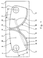
- the self-locking jaw suspension device comprises a base 1 and at least a couple of two jaw blocks 2 and 3 mounted to rotate on the base 1 along two respective parallel axes 4 and 5.
- Each of the jaw blocks such as the jaw block 2 is limited by an anterior face 6, a posterior face 7, both flat and parallel to each other, and perpendicular to the respective axis 4, and a peripheral face 8.
- the peripheral face portion 8 which is facing the other jaw block is a support face 9, curvilinear eccentric, developing between a first end 10 distant from the respective axis of rotation 4 and a second end 11 close to the axis of rotation.
- the second jaw block 3 comprises a bearing face 12 extending between a first end 13 and a second end 14.
- the axes of rotation 4 and 5 are spaced apart by a distance suitable so that the jaw blocks 2 and 3 can pivot between a clamping position illustrated in Figure 1 and a release illustrated in FIG. 2.
- the first respective end portions 10 and 13 of bearing faces 9 and 12 are opposite one another, close together or in support one against the other.
- the second respective end portions 11 and 14 of the faces support 9 and 12 are facing each other to leave a space free 15 between the two jaw blocks 2 and 3.
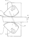
- a synchronization device ensures the synchronization of rotation of the jaw blocks 2 and 3 of the flow of jaw blocks according to reverse rotations around their respective axes 4 and 5, between the clamping position illustrated in Figure 1 and the release position illustrated in figure 2.
- the synchronization device comprises a rod 16 with two ends 17 and 18 parallel, as can be seen better in FIG. 3, the ends 17 and 18 being connected to a portion central 19 by two respective bent portions 20 and 21.
- the portion rod center 19 can for example be rectilinear, and be arranged near the base 1.
- the first rod end 17 is engaged in a first blind hole 22 of the first jaw block 2, while the second end 18 of rod is engaged in a second blind hole 23 of the second block jaw 3 of the pair of jaw blocks.
- the first and second holes 22 and 23 are parallel to the corresponding axis of rotation 4 or 5, and spaced apart of said axis 4 or 5 substantially along the same predetermined spacing L.
- the first hole 22 is in the area of first jaw block 2 extending between the axis of rotation 4 and the second end portion 11 from the front support 9.
- the second hole 23 is in the area of the second jaw block 3 extending between the axis of rotation 5 and the first end portion 13 support face 12. In the clamping position, the rod 16 is thus arranged in an obligatory orientation illustrated in FIG. 1.
- a first stop 25 projecting from the base 1, and limiting the movement of the rod 16 beyond the release position: on FIG. 2, the rod 16 comes to bear against the first stop 25, preventing additional rotational movement of the jaw blocks 2 and 3 beyond the release position.
- a second stop 24 protruding from the base 1, and limiting the movement of the rod 16 beyond the clamping position: in FIG. 1, the rod 16 bears against the second stop 24, prohibits rotation additional jaw blocks 2 and 3 beyond the position of Tightening. It will be noted that this second stop 24 may be useless if, in the clamping position, the first ends 10 and 13 of faces 9 and 12 of the jaw blocks 2 and 3 come to bear against one the other above the plane passing through the two axes of rotation 4 and 5.
- each jaw block such as the jaw block 2 is held on the base 1 by a screw 26 with head 27, freely rotating in an axial hole 28 of the jaw block 2, the head 27 bearing against the anterior face 6 of the block jaw 2, the end portion 126 of rod 26 of screw passing through without clearance an axial hole 29 of the base 1 and receiving a tightening nut 30 carrying against the rear face 31 of the base 1.
- a tubular spacer 32 is engaged on the screw rod 26, and interposed between the front face 33 of the base 1 and the rear face 7 of the jaw block 2, to determine the spacing E separating the jaw block 2 and the base 1.
- a locking nut 38 can advantageously be provided, mounted on the intermediate part of the rod screw 26, to ensure a tightening of the base 1 on its two faces.
- the screw 26 to head 27 includes a proximal part of rod 226 with a smooth external surface and slightly longer than the thickness of the jaw block 2 increased by the length of the spacer 32.
- the proximal part of the rod 226 is connected by a shoulder 326 to the end portion 126 of the rod itself threaded and of reduced section.
- a washer 138 is engaged between the shoulder 326 and the base 1. This improves, at cost reduced, the freedom of rotation of the jaw block 2, and it facilitates the mounting.
- the base 1 could advantageously be made of wood.
- Blocks jaws can also be made of wood.
- the bearing faces 9 and 12 of the jaw blocks 2 and 3 are of preferably covered with a layer 34 or 35 of elastic material compressible and non-slip.
- the base 1 is generally parallelepiped and flat.
- the base carries, on one of its main faces, a single pair of two jaw blocks 2 and 3.
- a base 1 formed of a strip elongated along a longitudinal axis and bearing, on one of its faces main, a row of several pairs of identical jaw blocks to jaw blocks 2 and 3, the first ends of the bearing faces are located on the same side of the longitudinal axis of the base.
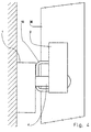
- the base 1 In use, as illustrated in Figures 4 and 5, the base 1 is fixed to a wall, so that the two axes 4 and 5 are horizontal and placed substantially on the same horizontal plane.
- An object 36 such as a snowboard, can be engaged between the two jaw blocks 2 and 3 in intermediate opening position, and the object's own weight 36, tending to move it down, causes the blocks to rotate jaws 2 and 3 in the clamping direction, so that the jaw blocks 2 and 3 tighten the object 36 and prohibit its movement down.
- For pick up the object just move it slightly upwards.
- to engage the object between the jaw blocks 2 and 3 initially in the clamping position of FIG. 1 it suffices to engage the object 36 in moving it up against the intermediate part of the jaw blocks 2 and 3, and jaw blocks 2 and 3, by rotation, move apart to authorize the engagement of object 36 to position illustrated in figure 5.
Landscapes
- Clamps And Clips (AREA)
- Orthopedics, Nursing, And Contraception (AREA)
- Hooks, Suction Cups, And Attachment By Adhesive Means (AREA)
- Floor Finish (AREA)
- Load-Engaging Elements For Cranes (AREA)
- Chain Conveyers (AREA)
Description
- la figure 1 est une vue de face d'un dispositif selon un mode de réalisation de la présente invention, en position de serrage, en l'absence d'objet à retenir ;
- la figure 2 est une vue de face du dispositif de la figure 1, en position de libération ;
- la figure 3 est une vue de dessous du dispositif de la figure 1 ;
- la figure 4 est une vue de côté du dispositif de la figure 1, en position de serrage d'un objet pour son maintien ;
- la figure 5 est une vue de face du dispositif de la figure 4, en position de serrage de l'objet ;
- la figure 6 est une vue éclatée illustrant un premier mode de réalisation de structure d'axe de rotation des mâchoires sur le socle ; et
- la figure 7 illustre un second mode de réalisation de structure d' axe de rotation des mâchoires sur le socle.
Claims (10)
- Dispositif de suspension à mâchoires autobloquantes, comprenant un socle (1) et au moins un couple de deux blocs mâchoires (2, 3) montés rotatifs sur le socle (1) selon deux axes parallèles (4, 5), avec des moyens (32) fixant l'écart (E) entre les blocs mâchoires (2, 3) et le socle (1), les blocs mâchoires (2, 3) du couple de blocs mâchoires étant symétriques l'un de l'autre par rapport au plan transversal médian les séparant, les blocs mâchoires (2, 3) ayant des faces d'appui (9, 12) curvilignes excentrées, se développant entre une première extrémité (10, 13) éloignée de l'axe (4, 5) et une seconde extrémité (11, 14) rapprochée de l'axe (4, 5), un dispositif de synchronisation assurant la synchronisation des blocs mâchoires (2, 3) du couple de blocs mâchoires selon des rotations inverses autour de leurs axes respectifs (4, 5), entre une position de serrage dans laquelle les premières portions d' extrémité respectives (10, 13) de faces d'appui (9, 12) sont en regard l'une de l'autre, rapprochées ou en appui l'une contre l'autre, et une position de libération dans laquelle les secondes portions d' extrémité respectives (11, 14) de faces d'appui (9, 12) sont en regard l'une de l'autre pour laisser un espace libre (15) entre les deux blocs mâchoires (2, 3), caractérisé en ce que :
le dispositif de synchronisation comprend une tringle (16) à deux extrémités (17, 18) parallèles raccordées à une partie centrale (19) par des portions coudées (20, 21), la portion centrale (19) de tringle étant à proximité du socle (1), la première extrémité (17) de tringle étant engagée dans un premier trou (22) du premier bloc mâchoire (2), la seconde extrémité (18) de tringle étant engagée dans un second trou (23) du second bloc mâchoire (3) du couple de blocs mâchoires, les premier (22) et second (23) trous étant parallèles à l'axe de rotation (4, 5) correspondant et écartés dudit axe de rotation selon un écartement (L) prédéterminé, le premier trou (22) étant dans la zone de premier bloc mâchoire (2) s'étendant entre l'axe de rotation (4) et la seconde portion d'extrémité (11) de face d'appui, le second trou (23) étant dans la zone de second bloc mâchoire (3) s'étendant entre l'axe de rotation (5) et la première portion d'extrémité (13) de face d'appui. - Dispositif de suspension selon la revendication 1, caractérisé en ce qu'une première butée (25), dépassant du socle (1), limite le mouvement de la tringle (16) au-delà de la position de libération.
- Dispositif de suspension selon l'une des revendications 1 ou 2, caractérisé en ce qu'une seconde butée (24), dépassant du socle (1), limite le déplacement de la tringle (16) au-delà de la position de serrage.
- Dispositif de suspension selon l'une quelconque des revendications 1 à 3, caractérisé en ce que chaque bloc mâchoire (2) est tenu sur le socle (1) par une vis (26) à tête (27), tourillonnant librement dans un trou axial (28) du bloc mâchoire (2), la tête (27) de vis portant contre la face antérieure (6) du bloc mâchoire (2), la portion d'extrémité (126) de tige de vis (26) traversant sans jeu un trou axial (29) du socle (1) et recevant un écrou de serrage (30) portant contre la face arrière (31) du socle (1), avec une entretoise tubulaire (32) engagée sur la tige de vis (26) et interposée entre la face avant (33) du socle (1) et la face postérieure (7) du bloc mâchoire (2) pour déterminer l'écartement (E) séparant le bloc mâchoire (2) et le socle (1).
- Dispositif de suspension selon la revendication 4, caractérisé en ce que la vis (26) à tête (27) comprend une partie proximale de tige (226) lisse et de longueur légèrement supérieure à l'épaisseur du bloc mâchoire (2) augmentée de la longueur de l'entretoise (32), se raccordant par un épaulement (326) à une portion d'extrémité (126) filetée à section réduite, avec une rondelle (138) engagée entre l'épaulement (326) et le socle (1).
- Dispositif de suspension selon l'une quelconque des revendications 1 à 5, caractérisé en ce que le socle (1) est en bois.
- Dispositif de suspension selon l'une quelconque des revendications 1 à 6, caractérisé en ce que les blocs mâchoires (2, 3) sont en bois.
- Dispositif de suspension selon l'une quelconque des revendications 1 à 7, caractérisé en ce que les faces d'appui (9, 12) des blocs mâchoires (2, 3) sont recouvertes d'une couche (34, 35) de matériau élastiquement compressible et antidérapant.
- Dispositif de suspension selon l'une quelconque des revendications 1 à 8, caractérisé en ce que le socle (1) est généralement parallélépipédique et plat, et porte, sur l'une de ses faces principales, un seul couple de deux blocs mâchoires (2, 3).
- Dispositif de suspension selon l'une quelconque des revendications 1 à 9, caractérisé en ce que le socle (1) est une bande allongée selon un axe longitudinal et portant, sur l'une de ses faces principales, une rangée de plusieurs couples de blocs mâchoires dont les premières extrémités de faces d'appui sont situées d'un même' côté de l'axe longitudinal du socle.
Applications Claiming Priority (3)
| Application Number | Priority Date | Filing Date | Title |
|---|---|---|---|
| FR9515791 | 1995-12-14 | ||
| FR9515791A FR2742496B1 (fr) | 1995-12-14 | 1995-12-14 | Dispositif de suspension a machoires autobloquantes |
| PCT/FR1996/001950 WO1997021379A1 (fr) | 1995-12-14 | 1996-12-06 | Dispositif de suspension a machoires autobloquantes |
Publications (2)
| Publication Number | Publication Date |
|---|---|
| EP0868142A1 EP0868142A1 (fr) | 1998-10-07 |
| EP0868142B1 true EP0868142B1 (fr) | 1999-08-25 |
Family
ID=9486193
Family Applications (1)
| Application Number | Title | Priority Date | Filing Date |
|---|---|---|---|
| EP96941713A Expired - Lifetime EP0868142B1 (fr) | 1995-12-14 | 1996-12-06 | Dispositif de suspension a machoires autoblocantes |
Country Status (8)
| Country | Link |
|---|---|
| US (1) | US6105915A (fr) |
| EP (1) | EP0868142B1 (fr) |
| JP (1) | JP2000501631A (fr) |
| AT (1) | ATE183626T1 (fr) |
| AU (1) | AU1100997A (fr) |
| DE (1) | DE69603975T2 (fr) |
| FR (1) | FR2742496B1 (fr) |
| WO (1) | WO1997021379A1 (fr) |
Families Citing this family (17)
| Publication number | Priority date | Publication date | Assignee | Title |
|---|---|---|---|---|
| US6533234B2 (en) * | 2000-09-29 | 2003-03-18 | Hach Company | Self-centering system |
| US6474612B2 (en) * | 2000-12-29 | 2002-11-05 | Boyd E. Ross, Jr. | Pool stick hanging device |
| EP1621846B1 (fr) * | 2004-07-23 | 2012-12-26 | Dr. Johannes Heidenhain GmbH | Pré-assemblage d'un capteur |
| US20070034762A1 (en) * | 2005-08-15 | 2007-02-15 | Russell White | Variable article holder |
| US8403958B2 (en) * | 2006-08-21 | 2013-03-26 | Warsaw Orthopedic, Inc. | System and method for correcting spinal deformity |
| US7896175B1 (en) | 2007-01-24 | 2011-03-01 | Steven Corr | Weight activated storage device |
| US7793902B2 (en) * | 2007-05-10 | 2010-09-14 | Gaymar Industries, Inc. | Medical device clamp |
| USD617989S1 (en) | 2009-03-20 | 2010-06-22 | Helen Of Troy Limited | Organizer |
| US20120049020A1 (en) * | 2010-08-31 | 2012-03-01 | Stock Daniel F | Holder for variable sizes of tools and implements |
| US8733719B2 (en) | 2010-11-12 | 2014-05-27 | Wildcard Enterprises Llc | Method and apparatus for use in management of medical intravenous pole assemblies |
| DE102012018175B3 (de) | 2012-09-14 | 2013-12-12 | Ferdinand Likosar | Universal-Klemmhalter zur Halterung von Gegenständen beliebiger Art |
| USD988849S1 (en) * | 2020-05-11 | 2023-06-13 | Shurtape Technologies, Llc | Tool holder |
| USD1008694S1 (en) * | 2023-08-04 | 2023-12-26 | Shenzhen Maining Innovation Technology Co., Ltd. | Ski wall rack |
| USD1030355S1 (en) * | 2023-08-04 | 2024-06-11 | Shenzhen Maining Innovation Technology Co., Ltd. | Ski storage rack |
| USD1005007S1 (en) * | 2023-08-04 | 2023-11-21 | Shenzhen Maining Innovation Technology Co., Ltd. | Ski wall rack |
| US12364256B1 (en) * | 2024-12-06 | 2025-07-22 | Yuerui Xu | Fishing rod holder |
| USD1062288S1 (en) * | 2024-12-09 | 2025-02-18 | Shenzhen Xiazijaye Trading Co., Ltd. | Fishing rod rack |
Family Cites Families (16)
| Publication number | Priority date | Publication date | Assignee | Title |
|---|---|---|---|---|
| US101062A (en) * | 1870-03-22 | Improved clamp for holding brooms, brushes | ||
| US164088A (en) * | 1875-06-08 | Improvement in holders for brooms | ||
| US243898A (en) * | 1881-07-05 | William hill | ||
| US369318A (en) * | 1887-09-06 | Broom or mop holder | ||
| US1306585A (en) * | 1919-06-10 | And george a | ||
| FR321861A (fr) * | 1902-06-06 | 1903-01-21 | Candillon Prudent | Porte-balai à action excentrique |
| US1589616A (en) * | 1923-12-31 | 1926-06-22 | Alford Hubert Goodson | Broom holder |
| US1563817A (en) * | 1924-06-18 | 1925-12-01 | Richard G Wright | Broom holder |
| CH113521A (de) * | 1925-03-18 | 1926-01-16 | Eggmann Laesser Max | Halter für Geräte mit Stielen oder Verlängerungen. |
| CH193030A (de) * | 1937-01-08 | 1937-09-30 | Solenthaler Johann | Aufhängevorrichtung für Besen, Flaumer und dergl. Stielgeräte. |
| CH235542A (de) * | 1943-08-04 | 1944-12-15 | Huber Keller Ulrich | Vorrichtung zum Aufhängen von Stielgeräten. |
| CH342339A (de) * | 1956-03-28 | 1959-11-15 | Stadelmann Weber Elisabeth | Vorrichtung zum Aufhängen von mit Stielen versehenen Geräten aller Art |
| US4763797A (en) * | 1987-08-14 | 1988-08-16 | Egan George E | Ski rack |
| DE3818031A1 (de) * | 1988-05-27 | 1989-11-30 | Brauckmann & Proebsting | Vorrichtung zur halterung von werkzeugen |
| US5183164A (en) * | 1989-02-03 | 1993-02-02 | Snowboardlinik Und Handelsges M.B.H. | Clamping holder for suspending skis |
| US5417335A (en) * | 1993-12-23 | 1995-05-23 | White; Steven M. | Apparatus and methods for suspending a pair of skis or the like |
-
1995
- 1995-12-14 FR FR9515791A patent/FR2742496B1/fr not_active Expired - Fee Related
-
1996
- 1996-12-06 AT AT96941713T patent/ATE183626T1/de not_active IP Right Cessation
- 1996-12-06 DE DE69603975T patent/DE69603975T2/de not_active Expired - Lifetime
- 1996-12-06 JP JP09521784A patent/JP2000501631A/ja active Pending
- 1996-12-06 WO PCT/FR1996/001950 patent/WO1997021379A1/fr not_active Ceased
- 1996-12-06 EP EP96941713A patent/EP0868142B1/fr not_active Expired - Lifetime
- 1996-12-06 AU AU11009/97A patent/AU1100997A/en not_active Abandoned
-
1998
- 1998-12-06 US US09/077,752 patent/US6105915A/en not_active Expired - Fee Related
Also Published As
| Publication number | Publication date |
|---|---|
| FR2742496B1 (fr) | 1998-01-23 |
| US6105915A (en) | 2000-08-22 |
| DE69603975D1 (de) | 1999-09-30 |
| WO1997021379A1 (fr) | 1997-06-19 |
| DE69603975T2 (de) | 2000-04-27 |
| FR2742496A1 (fr) | 1997-06-20 |
| EP0868142A1 (fr) | 1998-10-07 |
| ATE183626T1 (de) | 1999-09-15 |
| AU1100997A (en) | 1997-07-03 |
| JP2000501631A (ja) | 2000-02-15 |
Similar Documents
| Publication | Publication Date | Title |
|---|---|---|
| EP0868142B1 (fr) | Dispositif de suspension a machoires autoblocantes | |
| CA2358902C (fr) | Dispositif de fixation comprenant une tige accrochee a un mur | |
| FR2830433A1 (fr) | Ensemble pour l'osteosynthese du rachis comprenant une tete d'organe d'ancrage et un outil pour la fixation de la tete | |
| FR2917952A1 (fr) | Table de verre avec systeme de retenue permettant de fixer un plateau de table de verre a un pied de table | |
| EP0319390B1 (fr) | Suspente pour élément d'ossature, en particulier pour plafond à ossature métallique | |
| EP2499712B1 (fr) | Support pour maintenir en position des objets allongés par rapport à une structure | |
| CA2077690A1 (fr) | Dispositif polyvalent de serrage destine a maintenir des objets sans les abimer et son procede d'utilisation | |
| EP0468841A1 (fr) | Convoyeur à bande sans fin | |
| CA2215569A1 (fr) | Dispositif de fixation d'un objet sur le bord d'un support plan, notamment d'un outil du type etau ou analogue sur un etabli | |
| FR3094280A1 (fr) | Mécanisme de serrage de boule d’attelage et porte-bicyclettes le comprenant | |
| FR2632539A1 (fr) | Fixation de ski de fond | |
| WO2001094045A1 (fr) | Porte-outil pour le montage d'un outil sur une presse plieuse | |
| FR2743864A1 (fr) | Appareil d'eclairage encastre | |
| FR2830072A1 (fr) | Dispositif de serrage pour balancoire d'interieur | |
| FR2657631A1 (fr) | Dispositif de fixation de rail de chemin de fer sur un support en beton ou en metal. | |
| FR2950558A3 (fr) | Outil a main pour le maintien et le serrage de panneaux. | |
| EP0127524A1 (fr) | Scie à chantourner | |
| EP0982100B1 (fr) | Dispositif de calage par serrage d'une pièce sur un arbre non cylindrique | |
| EP0114538B1 (fr) | Support de scie a bûches | |
| FR2829164A1 (fr) | Dispositif de positionnement d'au moins une plaque sous une ossature | |
| EP1101425A1 (fr) | Système de fixation ajustable sur des profilés | |
| FR3126743A1 (fr) | Systeme de fixation d’une conduite a une cloison | |
| FR2896849A1 (fr) | Dispositif de fixation d'un accessoire, du type audiovisuel ou informatique, en peripherie d'un support sensiblement plan | |
| FR2622828A1 (fr) | Element modulaire de support universel d'outil et application a un panneau universel de support d'outils | |
| FR2769934A1 (fr) | Support pour gouttiere |
Legal Events
| Date | Code | Title | Description |
|---|---|---|---|
| PUAI | Public reference made under article 153(3) epc to a published international application that has entered the european phase |
Free format text: ORIGINAL CODE: 0009012 |
|
| 17P | Request for examination filed |
Effective date: 19980709 |
|
| AK | Designated contracting states |
Kind code of ref document: A1 Designated state(s): AT BE CH DE ES FR GB IT LI NL PT |
|
| GRAG | Despatch of communication of intention to grant |
Free format text: ORIGINAL CODE: EPIDOS AGRA |
|
| 17Q | First examination report despatched |
Effective date: 19981119 |
|
| GRAG | Despatch of communication of intention to grant |
Free format text: ORIGINAL CODE: EPIDOS AGRA |
|
| GRAH | Despatch of communication of intention to grant a patent |
Free format text: ORIGINAL CODE: EPIDOS IGRA |
|
| GRAH | Despatch of communication of intention to grant a patent |
Free format text: ORIGINAL CODE: EPIDOS IGRA |
|
| GRAA | (expected) grant |
Free format text: ORIGINAL CODE: 0009210 |
|
| AK | Designated contracting states |
Kind code of ref document: B1 Designated state(s): AT BE CH DE ES FR GB IT LI NL PT |
|
| PG25 | Lapsed in a contracting state [announced via postgrant information from national office to epo] |
Ref country code: NL Free format text: LAPSE BECAUSE OF FAILURE TO SUBMIT A TRANSLATION OF THE DESCRIPTION OR TO PAY THE FEE WITHIN THE PRESCRIBED TIME-LIMIT Effective date: 19990825 Ref country code: IT Free format text: LAPSE BECAUSE OF FAILURE TO SUBMIT A TRANSLATION OF THE DESCRIPTION OR TO PAY THE FEE WITHIN THE PRE;WARNING: LAPSES OF ITALIAN PATENTS WITH EFFECTIVE DATE BEFORE 2007 MAY HAVE OCCURRED AT ANY TIME BEFORE 2007. THE CORRECT EFFECTIVE DATE MAY BE DIFFERENT FROM THE ONE RECORDED.SCRIBED TIME-LIMIT Effective date: 19990825 Ref country code: GB Free format text: LAPSE BECAUSE OF FAILURE TO SUBMIT A TRANSLATION OF THE DESCRIPTION OR TO PAY THE FEE WITHIN THE PRESCRIBED TIME-LIMIT Effective date: 19990825 Ref country code: ES Free format text: THE PATENT HAS BEEN ANNULLED BY A DECISION OF A NATIONAL AUTHORITY Effective date: 19990825 Ref country code: AT Free format text: LAPSE BECAUSE OF FAILURE TO SUBMIT A TRANSLATION OF THE DESCRIPTION OR TO PAY THE FEE WITHIN THE PRESCRIBED TIME-LIMIT Effective date: 19990825 |
|
| REF | Corresponds to: |
Ref document number: 183626 Country of ref document: AT Date of ref document: 19990915 Kind code of ref document: T |
|
| REG | Reference to a national code |
Ref country code: CH Ref legal event code: EP |
|
| REF | Corresponds to: |
Ref document number: 69603975 Country of ref document: DE Date of ref document: 19990930 |
|
| PG25 | Lapsed in a contracting state [announced via postgrant information from national office to epo] |
Ref country code: PT Free format text: LAPSE BECAUSE OF FAILURE TO SUBMIT A TRANSLATION OF THE DESCRIPTION OR TO PAY THE FEE WITHIN THE PRESCRIBED TIME-LIMIT Effective date: 19991125 |
|
| NLV1 | Nl: lapsed or annulled due to failure to fulfill the requirements of art. 29p and 29m of the patents act | ||
| GBV | Gb: ep patent (uk) treated as always having been void in accordance with gb section 77(7)/1977 [no translation filed] |
Effective date: 19990825 |
|
| PLBE | No opposition filed within time limit |
Free format text: ORIGINAL CODE: 0009261 |
|
| STAA | Information on the status of an ep patent application or granted ep patent |
Free format text: STATUS: NO OPPOSITION FILED WITHIN TIME LIMIT |
|
| 26N | No opposition filed | ||
| REG | Reference to a national code |
Ref country code: FR Ref legal event code: CL |
|
| REG | Reference to a national code |
Ref country code: FR Ref legal event code: CL |
|
| PGFP | Annual fee paid to national office [announced via postgrant information from national office to epo] |
Ref country code: DE Payment date: 20101208 Year of fee payment: 15 |
|
| PGFP | Annual fee paid to national office [announced via postgrant information from national office to epo] |
Ref country code: CH Payment date: 20111228 Year of fee payment: 16 |
|
| PGFP | Annual fee paid to national office [announced via postgrant information from national office to epo] |
Ref country code: BE Payment date: 20111227 Year of fee payment: 16 |
|
| BERE | Be: lapsed |
Owner name: *NAMAN MARC Effective date: 20121231 Owner name: *FORNIER PASCAL Effective date: 20121231 |
|
| REG | Reference to a national code |
Ref country code: CH Ref legal event code: PL |
|
| PG25 | Lapsed in a contracting state [announced via postgrant information from national office to epo] |
Ref country code: BE Free format text: LAPSE BECAUSE OF NON-PAYMENT OF DUE FEES Effective date: 20121231 |
|
| PG25 | Lapsed in a contracting state [announced via postgrant information from national office to epo] |
Ref country code: LI Free format text: LAPSE BECAUSE OF NON-PAYMENT OF DUE FEES Effective date: 20121231 Ref country code: DE Free format text: LAPSE BECAUSE OF NON-PAYMENT OF DUE FEES Effective date: 20130702 Ref country code: CH Free format text: LAPSE BECAUSE OF NON-PAYMENT OF DUE FEES Effective date: 20121231 |
|
| REG | Reference to a national code |
Ref country code: DE Ref legal event code: R119 Ref document number: 69603975 Country of ref document: DE Effective date: 20130702 |
|
| PGFP | Annual fee paid to national office [announced via postgrant information from national office to epo] |
Ref country code: FR Payment date: 20131218 Year of fee payment: 18 |
|
| REG | Reference to a national code |
Ref country code: FR Ref legal event code: ST Effective date: 20150831 |
|
| PG25 | Lapsed in a contracting state [announced via postgrant information from national office to epo] |
Ref country code: FR Free format text: LAPSE BECAUSE OF NON-PAYMENT OF DUE FEES Effective date: 20141231 |