EP0868143B1 - Appareil permettant de detecter les cellules malignes dans des tissus vivants - Google Patents
Appareil permettant de detecter les cellules malignes dans des tissus vivants Download PDFInfo
- Publication number
- EP0868143B1 EP0868143B1 EP96938878A EP96938878A EP0868143B1 EP 0868143 B1 EP0868143 B1 EP 0868143B1 EP 96938878 A EP96938878 A EP 96938878A EP 96938878 A EP96938878 A EP 96938878A EP 0868143 B1 EP0868143 B1 EP 0868143B1
- Authority
- EP
- European Patent Office
- Prior art keywords
- tissue sample
- laser
- pulse
- sample
- laser pulse
- Prior art date
- Legal status (The legal status is an assumption and is not a legal conclusion. Google has not performed a legal analysis and makes no representation as to the accuracy of the status listed.)
- Expired - Lifetime
Links
Images


Classifications
-
- A—HUMAN NECESSITIES
- A61—MEDICAL OR VETERINARY SCIENCE; HYGIENE
- A61B—DIAGNOSIS; SURGERY; IDENTIFICATION
- A61B5/00—Measuring for diagnostic purposes; Identification of persons
- A61B5/0059—Measuring for diagnostic purposes; Identification of persons using light, e.g. diagnosis by transillumination, diascopy, fluorescence
- A61B5/0082—Measuring for diagnostic purposes; Identification of persons using light, e.g. diagnosis by transillumination, diascopy, fluorescence adapted for particular medical purposes
- A61B5/0091—Measuring for diagnostic purposes; Identification of persons using light, e.g. diagnosis by transillumination, diascopy, fluorescence adapted for particular medical purposes for mammography
-
- A—HUMAN NECESSITIES
- A61—MEDICAL OR VETERINARY SCIENCE; HYGIENE
- A61B—DIAGNOSIS; SURGERY; IDENTIFICATION
- A61B5/00—Measuring for diagnostic purposes; Identification of persons
- A61B5/43—Detecting, measuring or recording for evaluating the reproductive systems
- A61B5/4306—Detecting, measuring or recording for evaluating the reproductive systems for evaluating the female reproductive systems, e.g. gynaecological evaluations
- A61B5/4312—Breast evaluation or disorder diagnosis
-
- G—PHYSICS
- G01—MEASURING; TESTING
- G01N—INVESTIGATING OR ANALYSING MATERIALS BY DETERMINING THEIR CHEMICAL OR PHYSICAL PROPERTIES
- G01N21/00—Investigating or analysing materials by the use of optical means, i.e. using sub-millimetre waves, infrared, visible or ultraviolet light
- G01N21/17—Systems in which incident light is modified in accordance with the properties of the material investigated
- G01N21/47—Scattering, i.e. diffuse reflection
- G01N21/4795—Scattering, i.e. diffuse reflection spatially resolved investigating of object in scattering medium
Definitions
- This invention relates to an apparatus for detecting malignancies in living, biological tissue, and in particular to a method and apparatus for detecting breast cancer.
- breast cancer has the highest incidence rate and the highest mortality rate of any cancer in the United States.
- breast cancer which affects more than eight percent of women, is the most deadly disease amongst this segment of our population.
- early detection and treatment are the best hopes for reducing the death rate due to this serious disease.
- Considerable efforts have been made to improve upon existing detection systems.
- existing screening methods rely on x-ray mammography, which gives rise to a concern about the possibility of developing cancer as a result of irradiation using x-rays.
- the use of ultrasound has also been proposed; however, ultrasonic techniques also have documented drawbacks.
- USA5371368 describes using an ultrafast time-space gate imaging technique to detect disease tissues in human breast tissues in-vivo.
- a laser source is used to pass light through the breast and ballistic and snake components are detected using a light detector
- the object of the present invention is to meet the above need by providing a relatively simple apparatus for detecting breast cancer which results in relatively clear images.
- images is meant maps of the scattering properties of breast tissue where it is believed that malignancies have different scattering properties than normal tissue.
- the method of detecting the presence of a malignant mass in a living tissue sample underlying the present invention comprises the steps of:
- the present invention relates to an apparatus for detecting the presence of a malignant mass in a living tissue sample comprising:
- an ultrafast laser pulse for example a laser pulse with a temporal length of less than a few picoseconds
- the light is scattered and decomposes into three classes of photons, namely ballistic, snake-like and diffused photons.
- Ballistic photons take a straight line path of travel 1 through the diffusing medium without being deviated by the medium. Images formed by such photons show maximum contrast and resolution.
- Snake-like photons are scattered slightly by the diffusing medium, and therefore take an approximately straight line path of travel 2 through the medium.
- the snake-like photons zig-zag around a straight line path of travel 1. Images formed by snake-like photons have lower contrast and resolution than ballistic photons.
- Diffused photons are subject to substantial scattering, taking an erratic path of travel 3 through the medium, and the images formed by such photons are completely blurred.
- snake-like photons In order to retrieve the information carried by snake-like photons, the latter must be separated from the diffuse photons. Since snake-like photons follow a straighter path of travel 2 than diffuse photons, they take less time to travel through the tissue and will arrive first at the side of the tissue opposite to the side to which the laser pulse is applied.
- the present inventors use this temporal dispersion to selectively retrieve the information imparted by snake-like photons.
- time-gating techniques it is possible to retrieve image information from the snake-like photons deleting the background from diffuse photons.
- the population of transmitted snake-like photons from a laser pulse passing through a tissue sample will be different for regions with different scattering coefficients.
- the present inventors use such photons to obtain a more precise evaluation of the scattering coefficient of a scanned region of a tissue sample, and consequently a better image.
- Fig. 2 The multiple field of view system used to characterize the diffusing or scattering properties of the breast tissue is illustrated in Fig. 2.
- a system of this type is described in United States Patent No. 5,239,352, which issued to Luc R. Bissonnette on August 24, 1993.
- the system includes an input aperture 5 for precisely defining the size of an input beam or laser pulse 6 entering a tissue sample 7.
- Light passing through the tissue sample 7 passes through an output aperture 8 which has a fixed or variable diameter for defining the scanned region.
- the light exiting the aperture 8 is scattered into separate field of view or cones I, II and III, which have different emergent angles.
- the number of fields of view is not limited to three, the number shown being used for the purpose of illustration only.
- the cones I, II and III pass through a multiple field of view separator 9 which simultaneously separates the cones of light received from the sample 7, and separates the light into different, discrete fields of view or cones I', II' and III', i.e. at different angles depending upon the nature of the photons.
- the multiple scattered light enters a detector defined by a streak camera 10 which produces a streak image.
- the camera 10 provides laser outputs in the different fields of view I", II" and III".
- the multiple field of view system effects spatial separation of light emanating from the sample, and redirects the light into different fields of view, i.e. at different angles.
- the contributions for the different fields of view provide additional information and provide all that is necessary to determine the scattering coefficients ⁇ s of the medium.
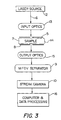
- the apparatus for carrying out the method of the present invention includes a laser source 12 for generating an ultrafast laser pulse 6 with emission wavelengths from 600 to 1500 nm, a temporal pulse length of 100 femtoseconds to 50 picoseconds and a pulse repetition rate of 60 to 120 kilohertz.
- a suitable laser source 12 is a modelocked titanium:sapphire laser pumped by an argon laser, a modelocked titanium:sapphire laser pumped by a frequency doubled Nd:YAG laser, a modelocked titanium:sapphire laser pumped by a frequency doubled ND:YLF laser, a modelocked diode laser, a modelocked Forsterite laser or a modelocked Cr:YAG laser.
- a modelocked laser generally has a pulse repetition of 60 to 120 KHz.
- the laser pulse 6 passes through input optics 13 defined by lenses, holographic elements, binary optics or an apodizer in order to modify the input laser pulse 6 to match the particular requirements of the tissue being investigated.
- the pulse 6 After passing through the input optics 13, the pulse 6 passes through the input aperture 5 to the tissue sample 7, which is mounted in a holder 14.
- the holder 14 is transparent to the pulse 6, and which effects a small compression of the breast to cause the tissue under investigation to assume a uniform thickness.
- the beam Upon exiting the sample 7, the beam passes through the output aperture 8 and output optics 15 to the holographic separator 9.
- the output optics 15 are defined by a lens, holographic elements, binary optics or an apodizer for modifying the parameters of the output beam in accordance with the character of the sample 7 being analyzed.
- the beam then enters the multiple field of view separator 9 for spatial separation of the light from the sample 7, and the scattering of such light into the different fields of view.
- the beam then passes to the streak camera 10, which yields results, which are fed to computer and data processing equipment 16.
- the equipment 16 produces an image of the area of tissue under examination.
Landscapes
- Health & Medical Sciences (AREA)
- Life Sciences & Earth Sciences (AREA)
- Physics & Mathematics (AREA)
- General Health & Medical Sciences (AREA)
- Pathology (AREA)
- Biomedical Technology (AREA)
- Veterinary Medicine (AREA)
- Heart & Thoracic Surgery (AREA)
- Medical Informatics (AREA)
- Molecular Biology (AREA)
- Surgery (AREA)
- Animal Behavior & Ethology (AREA)
- Biophysics (AREA)
- Public Health (AREA)
- Engineering & Computer Science (AREA)
- Gynecology & Obstetrics (AREA)
- Reproductive Health (AREA)
- Optics & Photonics (AREA)
- Chemical & Material Sciences (AREA)
- Analytical Chemistry (AREA)
- Biochemistry (AREA)
- General Physics & Mathematics (AREA)
- Immunology (AREA)
- Investigating Or Analysing Materials By Optical Means (AREA)
Claims (5)
- Appareil pour détecter la présence d'une masse maligne dans un échantillon de tissu vivant comprenant:(a) un moyen de laser (12) pour produire une impulsion laser ultrarapide;(b) un moyen de support (14) transparent à ladite impulsion pour supporter l'échantillon de tissu tandis que l'impulsion laser passe au travers, la lumière qui passe au travers de l'échantillon se diffusant selon des champs de visualisation séparés représentés par des premiers cônes de lumière qui présentent des angles d'émergence différents,
caractérisé par:(c) un moyen de séparateur de multiples champs de visualisation (9) pour une séparation spatiale simultanée des premiers cônes de lumière arrivant depuis l'échantillon selon différents champs de visualisation discrets définis par des seconds cônes présentant des angles d'émergence différents et pour effectuer une dispersion temporelle de l'impulsion laser qui sort de l'échantillon de tissu; et(d) un moyen de détecteur (10) pour résoudre temporellement l'impulsion laser qui sort de l'échantillon de tissu pour détecter lesdits différents champs de visualisation en provenance dudit moyen de séparateur (9) afin de constituer des données primaires pour un traitement afin de produire une image nette de l'intérieur de l'échantillon de tissu. - Appareil selon la révendication 1, dans lequel ledit moyen de laser (12) est une source laser qui peut générer une impulsion laser qui présente une longueur d'onde d'émission qui va de 600 nm à 1500 nm, une longueur impulsionnelle temporelle de 100 femtosecondes à 50 picosecondes et une fréquence de répétition d'impulsion de 60 kHz à 120 kHz.
- Appareil selon la revendication 2, incluant un moyen optique d'entrée (13) et une ouverture d'entrée (5) pour modifier l'impulsion laser ultrarapide avant passage de ladite impulsion dans l'échantillon de tissu.
- Appareil selon la revendication 3, incluant un moyen optique de sortie (15) pour modifier un faisceau de sortie en provenance de l'échantillon de tissu conformément au caractère de l'échantillon qui est analysé.
- Appareil selon la revendication 4, dans lequel ledit moyen de détecteur (10) inclut un moyen de caméra à image continue pour recevoir le faisceau modifié en provenance dudit moyen optique de sortie (15).
Applications Claiming Priority (4)
| Application Number | Priority Date | Filing Date | Title |
|---|---|---|---|
| CA2163914 | 1995-11-28 | ||
| CA002163914A CA2163914A1 (fr) | 1995-11-28 | 1995-11-28 | Methode et appareil permettant de deceler des tumeurs malignes dans les tissus vivants |
| US08/746,944 US5808304A (en) | 1995-11-28 | 1996-11-18 | Method and apparatus for detecting malignancies in living tissue |
| PCT/CA1996/000776 WO1997019632A1 (fr) | 1995-11-28 | 1996-11-26 | Procede et appareil permettant de detecter les cellules malignes dans des tissus vivants |
Publications (2)
| Publication Number | Publication Date |
|---|---|
| EP0868143A1 EP0868143A1 (fr) | 1998-10-07 |
| EP0868143B1 true EP0868143B1 (fr) | 2001-08-16 |
Family
ID=25678236
Family Applications (1)
| Application Number | Title | Priority Date | Filing Date |
|---|---|---|---|
| EP96938878A Expired - Lifetime EP0868143B1 (fr) | 1995-11-28 | 1996-11-26 | Appareil permettant de detecter les cellules malignes dans des tissus vivants |
Country Status (5)
| Country | Link |
|---|---|
| US (1) | US5808304A (fr) |
| EP (1) | EP0868143B1 (fr) |
| AU (1) | AU7615396A (fr) |
| CA (1) | CA2163914A1 (fr) |
| WO (1) | WO1997019632A1 (fr) |
Families Citing this family (6)
| Publication number | Priority date | Publication date | Assignee | Title |
|---|---|---|---|---|
| EP0877927A1 (fr) * | 1996-08-14 | 1998-11-18 | Koninklijke Philips Electronics N.V. | Dispositif et procede de formation d'image d'un objet opaque |
| US6377842B1 (en) | 1998-09-22 | 2002-04-23 | Aurora Optics, Inc. | Method for quantitative measurement of fluorescent and phosphorescent drugs within tissue utilizing a fiber optic probe |
| CA2259900A1 (fr) | 1999-01-22 | 2000-07-22 | Art Aerospace Research Technologies Inc. | Discrimination de profondeur |
| AU2002303819B2 (en) | 2001-05-17 | 2007-03-01 | Xenogen Corporation | Method and apparatus for determining target depth, brightness and size within a body region |
| WO2008036567A2 (fr) * | 2006-09-18 | 2008-03-27 | The Trustees Of Dartmouth College | Système et procédé de visualisation d'objets à travers des milieux troubles |
| GB201611819D0 (en) | 2016-07-07 | 2016-08-17 | Univ Court Of The Univ Of Edinburgh The | Imaging method and apparatus |
Family Cites Families (5)
| Publication number | Priority date | Publication date | Assignee | Title |
|---|---|---|---|---|
| US4948974A (en) * | 1984-06-25 | 1990-08-14 | Nelson Robert S | High resolution imaging apparatus and method for approximating scattering effects |
| JPH06100532B2 (ja) * | 1986-08-25 | 1994-12-12 | 浜松ホトニクス株式会社 | 高空間・時間分解計測装置 |
| US5140463A (en) * | 1990-03-08 | 1992-08-18 | Yoo Kwong M | Method and apparatus for improving the signal to noise ratio of an image formed of an object hidden in or behind a semi-opaque random media |
| CA2053758C (fr) * | 1991-10-18 | 2001-01-02 | Luc R. Bissonnette | Lidar a diffusion multiple |
| US5371368A (en) * | 1992-07-23 | 1994-12-06 | Alfano; Robert R. | Ultrafast optical imaging of objects in a scattering medium |
-
1995
- 1995-11-28 CA CA002163914A patent/CA2163914A1/fr not_active Abandoned
-
1996
- 1996-11-18 US US08/746,944 patent/US5808304A/en not_active Expired - Fee Related
- 1996-11-26 AU AU76153/96A patent/AU7615396A/en not_active Abandoned
- 1996-11-26 WO PCT/CA1996/000776 patent/WO1997019632A1/fr not_active Ceased
- 1996-11-26 EP EP96938878A patent/EP0868143B1/fr not_active Expired - Lifetime
Also Published As
| Publication number | Publication date |
|---|---|
| CA2163914A1 (fr) | 1997-05-29 |
| AU7615396A (en) | 1997-06-19 |
| US5808304A (en) | 1998-09-15 |
| WO1997019632A1 (fr) | 1997-06-05 |
| EP0868143A1 (fr) | 1998-10-07 |
Similar Documents
| Publication | Publication Date | Title |
|---|---|---|
| EP0555645B1 (fr) | Dispositif pour détecter la carie dentaire | |
| US5369496A (en) | Noninvasive method and apparatus for characterizing biological materials | |
| US5371368A (en) | Ultrafast optical imaging of objects in a scattering medium | |
| US6922583B1 (en) | Method for measuring tissue morphology | |
| Burns et al. | Direct measurement of human-cone-photoreceptor alignment | |
| EP0199767B1 (fr) | Systeme de mise en images par fluorescence | |
| JP4535697B2 (ja) | 生体組織の光散乱観測内視鏡装置 | |
| DE69525219T2 (de) | Verfahren und Vorrichtung zur Messung der Streu- und Absorptionsmerkmale eines streuenden Mediums | |
| US5799656A (en) | Optical imaging of breast tissues to enable the detection therein of calcification regions suggestive of cancer | |
| US7840257B2 (en) | Examination of biological tissue using non-contact optical probes | |
| US5719399A (en) | Imaging and characterization of tissue based upon the preservation of polarized light transmitted therethrough | |
| EP1845837B1 (fr) | Procede et appareil pour mesurer une evolution cancereuse a partir de mesures de reflectance spectrale obtenues par imagerie endoscopique | |
| US5813988A (en) | Time-resolved diffusion tomographic imaging in highly scattering turbid media | |
| US4649275A (en) | High resolution breast imaging device utilizing non-ionizing radiation of narrow spectral bandwidth | |
| JP3035336B2 (ja) | 血流測定装置 | |
| US20110301453A1 (en) | Method and System for Free Space Optical Tomography of Diffuse Media | |
| EP0580414A2 (fr) | Dispositif et procédé destinés à la mesure de l'absorption dans un milieu disperseur | |
| JPH04135551A (ja) | 光三次元像観察装置 | |
| KR20010110346A (ko) | 편광을 사용하여 조직을 이미지화시키는 방법 | |
| US5386819A (en) | Method and apparatus for inhibiting a scattered component in a light having passed through an examined object | |
| WO2016022757A1 (fr) | Endoscopie térahertz à canal unique | |
| EP0868143B1 (fr) | Appareil permettant de detecter les cellules malignes dans des tissus vivants | |
| DE60035484T2 (de) | Tiefenunterscheidung von heterogenitäten in trüben medien | |
| CN101404925A (zh) | 用于混浊介质成像的设备 | |
| US20060187533A1 (en) | Method and device for time-gated amplification of photons |
Legal Events
| Date | Code | Title | Description |
|---|---|---|---|
| PUAI | Public reference made under article 153(3) epc to a published international application that has entered the european phase |
Free format text: ORIGINAL CODE: 0009012 |
|
| 17P | Request for examination filed |
Effective date: 19980522 |
|
| AK | Designated contracting states |
Kind code of ref document: A1 Designated state(s): DE FR GB IT NL |
|
| 17Q | First examination report despatched |
Effective date: 19990304 |
|
| RAP3 | Party data changed (applicant data changed or rights of an application transferred) |
Owner name: ART ADVANCED RESEARCH TECHNOLOGIES INC. |
|
| RAP1 | Party data changed (applicant data changed or rights of an application transferred) |
Owner name: ART ADVANCED RESEARCH TECHNOLOGIES INC. |
|
| GRAG | Despatch of communication of intention to grant |
Free format text: ORIGINAL CODE: EPIDOS AGRA |
|
| RTI1 | Title (correction) |
Free format text: APPARATUS FOR DETECTING MALIGNANCIES IN LIVING TISSUE |
|
| GRAG | Despatch of communication of intention to grant |
Free format text: ORIGINAL CODE: EPIDOS AGRA |
|
| GRAH | Despatch of communication of intention to grant a patent |
Free format text: ORIGINAL CODE: EPIDOS IGRA |
|
| GRAH | Despatch of communication of intention to grant a patent |
Free format text: ORIGINAL CODE: EPIDOS IGRA |
|
| GRAA | (expected) grant |
Free format text: ORIGINAL CODE: 0009210 |
|
| AK | Designated contracting states |
Kind code of ref document: B1 Designated state(s): DE FR GB IT NL |
|
| PG25 | Lapsed in a contracting state [announced via postgrant information from national office to epo] |
Ref country code: IT Free format text: LAPSE BECAUSE OF FAILURE TO SUBMIT A TRANSLATION OF THE DESCRIPTION OR TO PAY THE FEE WITHIN THE PRESCRIBED TIME-LIMIT;WARNING: LAPSES OF ITALIAN PATENTS WITH EFFECTIVE DATE BEFORE 2007 MAY HAVE OCCURRED AT ANY TIME BEFORE 2007. THE CORRECT EFFECTIVE DATE MAY BE DIFFERENT FROM THE ONE RECORDED. Effective date: 20010816 |
|
| REF | Corresponds to: |
Ref document number: 69614566 Country of ref document: DE Date of ref document: 20010920 |
|
| ET | Fr: translation filed | ||
| REG | Reference to a national code |
Ref country code: GB Ref legal event code: IF02 |
|
| PLBE | No opposition filed within time limit |
Free format text: ORIGINAL CODE: 0009261 |
|
| STAA | Information on the status of an ep patent application or granted ep patent |
Free format text: STATUS: NO OPPOSITION FILED WITHIN TIME LIMIT |
|
| 26N | No opposition filed | ||
| PGFP | Annual fee paid to national office [announced via postgrant information from national office to epo] |
Ref country code: FR Payment date: 20021108 Year of fee payment: 7 |
|
| PGFP | Annual fee paid to national office [announced via postgrant information from national office to epo] |
Ref country code: GB Payment date: 20021120 Year of fee payment: 7 |
|
| PGFP | Annual fee paid to national office [announced via postgrant information from national office to epo] |
Ref country code: DE Payment date: 20021128 Year of fee payment: 7 |
|
| PGFP | Annual fee paid to national office [announced via postgrant information from national office to epo] |
Ref country code: NL Payment date: 20021129 Year of fee payment: 7 |
|
| PG25 | Lapsed in a contracting state [announced via postgrant information from national office to epo] |
Ref country code: GB Free format text: LAPSE BECAUSE OF NON-PAYMENT OF DUE FEES Effective date: 20031126 |
|
| PG25 | Lapsed in a contracting state [announced via postgrant information from national office to epo] |
Ref country code: NL Free format text: LAPSE BECAUSE OF NON-PAYMENT OF DUE FEES Effective date: 20040601 |
|
| PG25 | Lapsed in a contracting state [announced via postgrant information from national office to epo] |
Ref country code: DE Free format text: LAPSE BECAUSE OF NON-PAYMENT OF DUE FEES Effective date: 20040602 |
|
| GBPC | Gb: european patent ceased through non-payment of renewal fee |
Effective date: 20031126 |
|
| PG25 | Lapsed in a contracting state [announced via postgrant information from national office to epo] |
Ref country code: FR Free format text: LAPSE BECAUSE OF NON-PAYMENT OF DUE FEES Effective date: 20040730 |
|
| NLV4 | Nl: lapsed or anulled due to non-payment of the annual fee |
Effective date: 20040601 |
|
| REG | Reference to a national code |
Ref country code: FR Ref legal event code: ST |