EP0868221B1 - In drucktaste eingebaute vordruckpumpe - Google Patents
In drucktaste eingebaute vordruckpumpe Download PDFInfo
- Publication number
- EP0868221B1 EP0868221B1 EP96941079A EP96941079A EP0868221B1 EP 0868221 B1 EP0868221 B1 EP 0868221B1 EP 96941079 A EP96941079 A EP 96941079A EP 96941079 A EP96941079 A EP 96941079A EP 0868221 B1 EP0868221 B1 EP 0868221B1
- Authority
- EP
- European Patent Office
- Prior art keywords
- pump
- pusher
- precompression
- fixed part
- piston
- Prior art date
- Legal status (The legal status is an assumption and is not a legal conclusion. Google has not performed a legal analysis and makes no representation as to the accuracy of the status listed.)
- Expired - Lifetime
Links
- 230000000284 resting effect Effects 0.000 claims description 2
- 238000009434 installation Methods 0.000 claims 2
- 238000004519 manufacturing process Methods 0.000 description 5
- 230000003247 decreasing effect Effects 0.000 description 2
- 238000006073 displacement reaction Methods 0.000 description 2
- 230000000694 effects Effects 0.000 description 2
- 230000003292 diminished effect Effects 0.000 description 1
- 238000007666 vacuum forming Methods 0.000 description 1
Images
Classifications
-
- B—PERFORMING OPERATIONS; TRANSPORTING
- B05—SPRAYING OR ATOMISING IN GENERAL; APPLYING FLUENT MATERIALS TO SURFACES, IN GENERAL
- B05B—SPRAYING APPARATUS; ATOMISING APPARATUS; NOZZLES
- B05B11/00—Single-unit hand-held apparatus in which flow of contents is produced by the muscular force of the operator at the moment of use
- B05B11/01—Single-unit hand-held apparatus in which flow of contents is produced by the muscular force of the operator at the moment of use characterised by the means producing the flow
- B05B11/10—Pump arrangements for transferring the contents from the container to a pump chamber by a sucking effect and forcing the contents out through the dispensing nozzle
- B05B11/1001—Piston pumps
- B05B11/1005—Piston pumps with means for adjusting or modifying pump stroke
- B05B11/1007—Piston pumps with means for adjusting or modifying pump stroke by adjusting or modifying the pump end-of-sucking-stroke position
-
- B—PERFORMING OPERATIONS; TRANSPORTING
- B05—SPRAYING OR ATOMISING IN GENERAL; APPLYING FLUENT MATERIALS TO SURFACES, IN GENERAL
- B05B—SPRAYING APPARATUS; ATOMISING APPARATUS; NOZZLES
- B05B11/00—Single-unit hand-held apparatus in which flow of contents is produced by the muscular force of the operator at the moment of use
- B05B11/01—Single-unit hand-held apparatus in which flow of contents is produced by the muscular force of the operator at the moment of use characterised by the means producing the flow
- B05B11/10—Pump arrangements for transferring the contents from the container to a pump chamber by a sucking effect and forcing the contents out through the dispensing nozzle
- B05B11/1001—Piston pumps
- B05B11/1004—Piston pumps comprising a movable cylinder and a stationary piston
-
- B—PERFORMING OPERATIONS; TRANSPORTING
- B05—SPRAYING OR ATOMISING IN GENERAL; APPLYING FLUENT MATERIALS TO SURFACES, IN GENERAL
- B05B—SPRAYING APPARATUS; ATOMISING APPARATUS; NOZZLES
- B05B11/00—Single-unit hand-held apparatus in which flow of contents is produced by the muscular force of the operator at the moment of use
- B05B11/01—Single-unit hand-held apparatus in which flow of contents is produced by the muscular force of the operator at the moment of use characterised by the means producing the flow
- B05B11/10—Pump arrangements for transferring the contents from the container to a pump chamber by a sucking effect and forcing the contents out through the dispensing nozzle
- B05B11/1038—Pressure accumulation pumps, i.e. pumps comprising a pressure accumulation chamber
- B05B11/104—Pressure accumulation pumps, i.e. pumps comprising a pressure accumulation chamber the outlet valve being opened by pressure after a defined accumulation stroke
-
- B—PERFORMING OPERATIONS; TRANSPORTING
- B05—SPRAYING OR ATOMISING IN GENERAL; APPLYING FLUENT MATERIALS TO SURFACES, IN GENERAL
- B05B—SPRAYING APPARATUS; ATOMISING APPARATUS; NOZZLES
- B05B11/00—Single-unit hand-held apparatus in which flow of contents is produced by the muscular force of the operator at the moment of use
- B05B11/01—Single-unit hand-held apparatus in which flow of contents is produced by the muscular force of the operator at the moment of use characterised by the means producing the flow
- B05B11/10—Pump arrangements for transferring the contents from the container to a pump chamber by a sucking effect and forcing the contents out through the dispensing nozzle
- B05B11/1042—Components or details
- B05B11/1073—Springs
- B05B11/1074—Springs located outside pump chambers
Definitions
- the present invention relates to a device for dispensing of product contained in a container, and more especially a precompression pump.
- Current pumps generally have a body pump comprising a pump chamber, a valve inlet valve, outlet valve, piston sliding in said pump body and an actuating rod for activate the pump using a button.
- Current precompression pumps include generally also a differential piston forming outlet valve and sliding in the pump body or on the actuating rod, under the effect of a spring precompression.
- the object of the present invention is to provide a pump with improved precompression, which does not have the disadvantages mentioned above.
- the object of the present invention is to provide a new precompression pump consisting of less than parts than current pumps, and therefore cheaper to manufacture and easier to assemble.
- the present invention aims to provide such a pump having only one spring and having no actuating rod.
- the present invention also aims to provide a new precompression pump with height diminished.
- the invention aims to provide such a pump in which the dead volume is minimized.
- Another object of the present invention is to provide a such an improved precompression pump where the volume of the dose expelled on each actuation can be modified by the user, without increasing manufacturing costs.
- the invention therefore relates to a pump precompression to selectively distribute a product contained in a container, said pump comprising a pump chamber comprising an inlet valve, a piston sliding in a first cylinder, a piston differential forming an outlet valve of said chamber pump, and sliding in a second cylinder between a closed position and an open position of the pump chamber, said pump further comprising a pusher provided with a dispensing orifice, said pusher being movable between a rest position and a position pump actuation, characterized in that said first and second cylinders are directly formed by respective first and second interior walls said pusher, said pusher thus delimiting in part said pump chamber, and in that said pump does not has only one spring resting on one side on a part of the pusher and on the other side on part of the differential piston, said spring acting on the one hand as a return spring from the pusher to its position rest, and secondly as a precompression spring for the differential piston.
- the pump according to the invention has the advantage to eliminate in particular the actuating rod and one of the two return and precompression springs.
- the height of the pump and the dead volume are therefore strongly reduced, the pump chamber and the single spring are located inside the pusher, and the number of parts components of the pump is decreased, so that its manufacturing and mounting are more economical, both from the point of view of time than from the point of view of cost.
- said piston is fixed relative to the container.
- said pump comprises a fixed part intended to be fixed on the neck of the container, said piece fixed partially delimiting the pump chamber and incorporating said piston, said sliding pusher sealingly on said fixed part.
- said fixed part also forms the seat of said pump chamber inlet valve, said fixed piston being formed by an annular lip of said fixed part sliding tightly in said first cylinder of said pusher.
- said fixed part further comprises means for fixing the pump to the neck of the container. So the use of a fixing ring reported is deleted, further decreasing the number component parts of the pump.
- said means for fixing the pump on the neck of the container are legs snap intended to snap onto said collar of the container, and cooperating after their snap-fastening, with a hoop which is intended to be mounted around said legs to hold said fixed part fixedly on the collar.
- said hoop after mounting on the fixed part, cooperates at its upper end with the pusher to form a stop defining the position of rest of said pusher.
- said hoop after its mounting on said fixed part is movable relative thereto between two limit positions to define at least two different pump chamber volumes. User can thus adjust as desired the volume of the dose of product which will be expelled on each actuation.
- the mounting and / or moving of said hoop on said fixed part is produced by screwing.
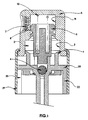
- the precompression pump comprises a piston 1 which slides in a first cylinder 2 formed directly in the pusher 6.
- the pump includes a differential piston providing precompression and sliding in a second cylinder 11 also formed directly in the pusher 6.
- the pump chamber 3 is therefore located partly at inside the pusher 6.
- the piston 1 is preferably fixed and made advantageously an integral part of a fixed part 20 which is fixed on the neck of the container (not shown), for example by means of snap tabs 22 and a hoop 21, which comes to be mounted around said legs 22.
- This fixed part 20 therefore acts as a body part pump by partially delimiting the pump chamber 3, and by receiving for example a ball 4 to form its valve entry.
- the fixed part 20 forms, by a annular lip, piston 1.
- it also acts advantageously as a fixing ring.
- said annular lip forming the piston 1 slides tightly in said first cylinder 2 formed directly by an inner wall of the push-button 6.
- the differential piston 5 slides in said second cylinder 11 formed directly by a inner wall of pusher 6, between a position of closure, where it closes passage 8 between the pump 3 and the dispensing orifice 7, for example a nozzle, and an open position, where it opens said passage 8.
- the pump of the invention therefore has the advantage of operate in the same way as a conventional pump, while incorporating fewer component parts. Of more, due to the absence of an actuating rod, the height of the pump is greatly reduced. On the other hand, the single spring 15 of the pump located in the pusher minimizes the dead volume in the pump.
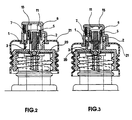
- the hoop 21 is movable relative to the fixed part 20, after having been mounted on it. So the rest position of the piston and therefore the volume of the pump chamber 3 can be changed or adjusted by the user.
- the hoop 21 is movable by screwing between two limit positions shown on Figures 2 and 3, but any other known means of displacement of the position of the hoop 21 relative to the fixed part 20 is conceivable (for example the axial displacement).
Landscapes
- Closures For Containers (AREA)
- Containers And Packaging Bodies Having A Special Means To Remove Contents (AREA)
- Reciprocating Pumps (AREA)
Claims (9)
- Pumpe mit Vorkompression zum selektiven Abgeben eines in einem Behälter enthaltenen Produktes, wobei die Pumpe eine Pumpenkammer (3) mit einem Eintrittsventil (4), einen in einem ersten Zylinder (2) gleitenden Kolben (1), einen Differenzialkolben (5), der ein Austrittsventil für die Pumpenkammer (3) bildet und in einem zweiten Zylinder (11) zwischen einer Verschlußstellung und einer Öffnungsstellung der Pumpenkammer (3) gleitet, umfaßt, wobei die Pumpe weiterhin einen mit einer Abgabeöffnung (7) versehenen Drücker (6) aufweist, wobei der Drücker (6) zwischen einer Ruhelage und einer Betätigungsstellung für die Pumpe beweglich ist, dadurch gekennzeichnet, daß der erste Zylinder (2) und der zweite Zylinder (11) direkt von einer ersten bzw. zweiten Innenwand des Drückers (6) gebildet werden, wobei der Drücker (6) somit teilweise die Pumpenkammer (3) umschließt, und daß die Pumpe nur eine einzige Feder (15) umfaßt, die auf der einen Seite an einem Teil des Drükkers (6) und auf der anderen Seite an einem Teil des Differentialkolbens (5) anliegt, wobei die Feder (15) einerseits als Rückholfeder für den Drücker (6) in seine Ruhelage und andererseits als Vorkompressionsfeder für den Differentialkolben (5) wirkt.
- Pumpe mit Vorkompression nach Anspruch 1, bei der der Kolben (1) bezüglich des Behälters fest ist.
- Pumpe mit Vorkompression nach Anspruch 2, bei der die Pumpe ein festes Element (20) umfaßt, das dazu dient, am Hals des Behälters befestigt zu werden, wobei dieses feste Element (20) teilweise die Pumpenkammer (3) umgrenzt und den Kolben (1) umfaßt, wobei der Drücker (6) in dichter Weise auf dem festen Element (20) gleitet.
- Pumpe mit Vorkompression nach Anspruch 3, bei der das feste Element (20) auch den Sitz des Eintrittsventils (4) der Pumpenkammer (3) bildet, wobei der feste Kolben (1) von einer ringförmigen Lippe (1) des festen Elements (20) gebildet wird, die in dichter Weise im ersten Zylinder (11) des Drückers (6) gleitet.
- Pumpe mit Vorkompression nach Anspruch 3 oder 4, bei der das feste Element (20) weiterhin Befestigungsmittel (22) für die Pumpe auf dem Hals des Behälters umfaßt.
- Pumpe mit Vorkompression nach Anspruch 5, bei der die Befestigungsmittel der Pumpe auf dem Hals des Behälters Rastklauen (22) sind, die dazu dienen, auf dem Hals des Behälters einzurasten und die nach ihrem Einrasten mit einem Ring (21) zusammenwirken, der dazu bestimmt ist, um die besagten Klauen (22) herum montiert zu werden, um das feste Element (20) fest am Hals zu halten.
- Pumpe mit Vorkompression nach Anspruch 6, bei der der Ring (21) nach seiner Montage auf dem festen Element (20) an seinem oberen Ende mit dem Drücker (6) zusammenwirkt, um einen Anschlag zu bilden, der die Ruhelage des Drückers (6) definiert.
- Pumpe mit Vorkompression nach Anspruch 7, bei der der Ring (21) nach seiner Montage auf dem festen Element (20) bezüglich dieses Elementes zwischen zwei begrenzten Positionen verschiebbar ist, um zumindest zwei verschiedene Volumina der Pumpenkammer (3) zu definieren.
- Pumpe mit Vorkompression nach Anspruch 8, bei der die Montage und/oder die Verschiebung des Rings (21) auf dem festen Element (20) durch Verschrauben realisiert ist.
Applications Claiming Priority (3)
| Application Number | Priority Date | Filing Date | Title |
|---|---|---|---|
| FR9515320A FR2742812B1 (fr) | 1995-12-22 | 1995-12-22 | Pompe a precompression formee dans le poussoir |
| FR9515320 | 1995-12-22 | ||
| PCT/FR1996/001895 WO1997023304A1 (fr) | 1995-12-22 | 1996-11-29 | Pompe a precompression formee dans le poussoir |
Publications (2)
| Publication Number | Publication Date |
|---|---|
| EP0868221A1 EP0868221A1 (de) | 1998-10-07 |
| EP0868221B1 true EP0868221B1 (de) | 2000-08-02 |
Family
ID=9485836
Family Applications (1)
| Application Number | Title | Priority Date | Filing Date |
|---|---|---|---|
| EP96941079A Expired - Lifetime EP0868221B1 (de) | 1995-12-22 | 1996-11-29 | In drucktaste eingebaute vordruckpumpe |
Country Status (6)
| Country | Link |
|---|---|
| US (1) | US6012615A (de) |
| EP (1) | EP0868221B1 (de) |
| DE (1) | DE69609628T2 (de) |
| ES (1) | ES2151189T3 (de) |
| FR (1) | FR2742812B1 (de) |
| WO (1) | WO1997023304A1 (de) |
Families Citing this family (15)
| Publication number | Priority date | Publication date | Assignee | Title |
|---|---|---|---|---|
| DE19739990A1 (de) * | 1997-09-11 | 1999-03-18 | Pfeiffer Erich Gmbh & Co Kg | Spender für Medien |
| US6374924B2 (en) * | 2000-02-18 | 2002-04-23 | Halliburton Energy Services, Inc. | Downhole drilling apparatus |
| GB2373520B (en) | 2000-02-18 | 2004-11-24 | Halliburton Energy Serv Inc | Downhole drilling apparatus and method for use of same |
| FR2806330B1 (fr) * | 2000-03-20 | 2002-10-25 | Valois Sa | Organe de distribution a clapet de sortie forme par un piston differentiel |
| FR2851483B1 (fr) * | 2003-02-20 | 2005-05-13 | Valois Sas | Tete de distribution |
| US7527177B2 (en) | 2003-12-22 | 2009-05-05 | Valois S.A.S. | Fluid dispenser member |
| US7789274B2 (en) | 2003-12-22 | 2010-09-07 | Valois S.A.S | Fluid dispenser member |
| FR2864045B1 (fr) | 2003-12-22 | 2006-03-31 | Valois Sas | Organe de distribution de produit fluide. |
| WO2005070560A1 (fr) * | 2003-12-22 | 2005-08-04 | Valois Sas | Organe de distribution de produit fluide et distributeur comprenant un tel organe |
| FR2864176B1 (fr) | 2003-12-22 | 2008-04-25 | Valois Sas | Pompe de distribution de produit fluide. |
| FR2864046B1 (fr) * | 2003-12-22 | 2006-12-01 | Valois Sas | Organe de distribution de produit fluide. |
| US7182225B2 (en) * | 2004-02-23 | 2007-02-27 | Valois S.A.S. | Fluid dispenser member |
| FR2866579B1 (fr) * | 2004-02-23 | 2006-05-26 | Valois Sas | Organe de distribution de produit fluide |
| FR2906232B1 (fr) | 2006-09-27 | 2008-12-12 | Valois Sas | Dispositif de distribution de produit fluide. |
| FR3041410A1 (fr) * | 2015-09-22 | 2017-03-24 | Cep Tubes | Systeme de distribution sans air avec pompe |
Family Cites Families (18)
| Publication number | Priority date | Publication date | Assignee | Title |
|---|---|---|---|---|
| US28366A (en) * | 1860-05-22 | Improvement in preserve-cans | ||
| US3216624A (en) * | 1964-05-25 | 1965-11-09 | Calmar Inc | Dispenser with stroke restricting overcap |
| USRE28366E (en) | 1966-11-21 | 1975-03-18 | Atomizing pump | |
| FR2346056A1 (fr) * | 1975-07-11 | 1977-10-28 | Step Soc Tech Pulverisation | Perfectionnements apportes aux vaporisateurs |
| US4111367A (en) * | 1977-02-18 | 1978-09-05 | Ethyl Corporation | Finger operated spray pump |
| US4174056A (en) * | 1977-05-10 | 1979-11-13 | Ciba-Geigy Corporation | Pump type dispenser with continuous flow feature |
| US4154374A (en) * | 1977-10-03 | 1979-05-15 | Ethyl Products Company | Finger operated spray pump |
| US4596344A (en) * | 1983-10-07 | 1986-06-24 | Corsette Douglas Frank | Manually actuated dispenser |
| US4618077A (en) * | 1984-03-07 | 1986-10-21 | Corsette Douglas Frank | Liquid dispensing pump |
| US4984702A (en) * | 1990-03-30 | 1991-01-15 | Specialty Packaging Licensing Company, Inc. | Assembly for securing and sealing a dispenser to a flanged container |
| US5192006A (en) * | 1991-05-01 | 1993-03-09 | Risdon Corporation | Low profile pump |
| FR2714119B1 (fr) * | 1993-12-22 | 1996-02-23 | Step | Pompe manuelle de pulvérisation à dose ajustable. |
| US5566865A (en) * | 1993-12-22 | 1996-10-22 | Valois S.A. | Manual atomizing pump with adjustable dosage |
| FR2715585B1 (fr) * | 1994-01-28 | 1996-03-08 | Oreal | Ensemble de distribution d'un liquide, de façon quasi-continue, comportant une pompe et utilisation d'un tel ensemble pour la pulvérisation d'une laque capillaire. |
| EP0688608A1 (de) * | 1994-03-25 | 1995-12-27 | GUALA S.p.A. | Sprühvorrichtung für handbetätigte Pumpen |
| FR2719242B1 (fr) * | 1994-04-27 | 1996-07-12 | Valois Sa | Pompe à précompression perfectionnée. |
| US5655688A (en) * | 1994-10-19 | 1997-08-12 | Aptargroup, Inc. | Atomizing pump with high stroke speed enhancement and valve system therefor |
| US5697530A (en) * | 1996-01-29 | 1997-12-16 | Monturas, S.A. | Precompression pump sprayer |
-
1995
- 1995-12-22 FR FR9515320A patent/FR2742812B1/fr not_active Expired - Fee Related
-
1996
- 1996-11-29 EP EP96941079A patent/EP0868221B1/de not_active Expired - Lifetime
- 1996-11-29 ES ES96941079T patent/ES2151189T3/es not_active Expired - Lifetime
- 1996-11-29 US US09/091,900 patent/US6012615A/en not_active Expired - Fee Related
- 1996-11-29 DE DE69609628T patent/DE69609628T2/de not_active Expired - Fee Related
- 1996-11-29 WO PCT/FR1996/001895 patent/WO1997023304A1/fr not_active Ceased
Also Published As
| Publication number | Publication date |
|---|---|
| ES2151189T3 (es) | 2000-12-16 |
| WO1997023304A1 (fr) | 1997-07-03 |
| DE69609628D1 (de) | 2000-09-07 |
| FR2742812A1 (fr) | 1997-06-27 |
| DE69609628T2 (de) | 2001-04-12 |
| US6012615A (en) | 2000-01-11 |
| EP0868221A1 (de) | 1998-10-07 |
| FR2742812B1 (fr) | 1998-02-20 |
Similar Documents
| Publication | Publication Date | Title |
|---|---|---|
| EP0868221B1 (de) | In drucktaste eingebaute vordruckpumpe | |
| EP1380520B1 (de) | Ausgabevorrichtung für einen Behälter mit einem Ventil | |
| EP1980332B1 (de) | Sprühpumpe für eine Flüssigkeit in einem Flakon | |
| EP1171367B1 (de) | Befestigungselement für flüssigkeitsabgabevorrichtungen und abgabevorrichtung die ein solches element enthält | |
| FR2704458A1 (fr) | Ensemble de distribution de produit. | |
| EP0905037A1 (de) | Ausgabekopf mit Verschlussvorrichtung | |
| EP1004523B1 (de) | Ventil für die Abgabe von Fluid unter Druck | |
| CA2565273A1 (fr) | Dispositif pour la distribution de produits liquides sans reprise d'air | |
| EP2069072B1 (de) | Spenderanordnung und spender für ein flüssigprodukt mit derartiger spenderanordnung | |
| EP1814672A1 (de) | Ein auslassventil und eine rückstellfeder für eine abgabevorrichtung bildendes flexibles teil | |
| FR2928357A1 (fr) | Obturateur d'organe de distribution de produit fluide. | |
| FR2621014A1 (fr) | Distributeur de produit pateux a fonctionnement ameliore et element de pompage correspondant | |
| EP1575709B1 (de) | Pumpe mit betätigungsknopf, insbesondere für kosmetische produkte | |
| EP0696233B1 (de) | Tragbares gerät zur abgabe einer flüssigkeit | |
| FR2877325A1 (fr) | Organe de distribution de produit fluide | |
| EP1430957A1 (de) | Behälter mit einer Pumpe | |
| WO2005063404A1 (fr) | Organe de distribution de produit fluide | |
| WO2007000536A2 (fr) | Valve de distribution de produit fluide. | |
| EP3694655B1 (de) | Vorrichtung zur ausgabe von flüssigen bis pastösen produkten und modulformende verschlussvorrichtung dafür | |
| EP4221900A1 (de) | Abgabevorrichtung mit einem festpunktrückschlagventil | |
| EP1948532B1 (de) | Pumpenauslöse- und -ausgabekopf | |
| FR2911123A1 (fr) | Piston suiveur, reservoir et distributeur comprenant un tel piston | |
| WO2022018365A1 (fr) | Machine d'extraction de liquide et procede d'extraction de liquide associe | |
| WO1997010899A1 (fr) | Dispositif de distribution de produit fluide du type a actionnement par ecrasement manuel | |
| WO1999061347A1 (fr) | Valve pour dispositif des fluides sous pression |
Legal Events
| Date | Code | Title | Description |
|---|---|---|---|
| PUAI | Public reference made under article 153(3) epc to a published international application that has entered the european phase |
Free format text: ORIGINAL CODE: 0009012 |
|
| 17P | Request for examination filed |
Effective date: 19980720 |
|
| AK | Designated contracting states |
Kind code of ref document: A1 Designated state(s): DE ES FR GB IT |
|
| GRAG | Despatch of communication of intention to grant |
Free format text: ORIGINAL CODE: EPIDOS AGRA |
|
| 17Q | First examination report despatched |
Effective date: 19991116 |
|
| GRAG | Despatch of communication of intention to grant |
Free format text: ORIGINAL CODE: EPIDOS AGRA |
|
| GRAH | Despatch of communication of intention to grant a patent |
Free format text: ORIGINAL CODE: EPIDOS IGRA |
|
| GRAH | Despatch of communication of intention to grant a patent |
Free format text: ORIGINAL CODE: EPIDOS IGRA |
|
| GRAA | (expected) grant |
Free format text: ORIGINAL CODE: 0009210 |
|
| RIN1 | Information on inventor provided before grant (corrected) |
Inventor name: DE POUS, OLIVIER Inventor name: BRUNET, MICHEL |
|
| AK | Designated contracting states |
Kind code of ref document: B1 Designated state(s): DE ES FR GB IT |
|
| REF | Corresponds to: |
Ref document number: 69609628 Country of ref document: DE Date of ref document: 20000907 |
|
| ITF | It: translation for a ep patent filed | ||
| GBT | Gb: translation of ep patent filed (gb section 77(6)(a)/1977) |
Effective date: 20001106 |
|
| REG | Reference to a national code |
Ref country code: ES Ref legal event code: FG2A Ref document number: 2151189 Country of ref document: ES Kind code of ref document: T3 |
|
| PLBE | No opposition filed within time limit |
Free format text: ORIGINAL CODE: 0009261 |
|
| STAA | Information on the status of an ep patent application or granted ep patent |
Free format text: STATUS: NO OPPOSITION FILED WITHIN TIME LIMIT |
|
| 26N | No opposition filed | ||
| REG | Reference to a national code |
Ref country code: GB Ref legal event code: IF02 |
|
| PGFP | Annual fee paid to national office [announced via postgrant information from national office to epo] |
Ref country code: DE Payment date: 20061108 Year of fee payment: 11 |
|
| PGFP | Annual fee paid to national office [announced via postgrant information from national office to epo] |
Ref country code: GB Payment date: 20061110 Year of fee payment: 11 |
|
| PGFP | Annual fee paid to national office [announced via postgrant information from national office to epo] |
Ref country code: ES Payment date: 20061113 Year of fee payment: 11 |
|
| PGFP | Annual fee paid to national office [announced via postgrant information from national office to epo] |
Ref country code: IT Payment date: 20061130 Year of fee payment: 11 |
|
| GBPC | Gb: european patent ceased through non-payment of renewal fee |
Effective date: 20071129 |
|
| PG25 | Lapsed in a contracting state [announced via postgrant information from national office to epo] |
Ref country code: DE Free format text: LAPSE BECAUSE OF NON-PAYMENT OF DUE FEES Effective date: 20080603 |
|
| PG25 | Lapsed in a contracting state [announced via postgrant information from national office to epo] |
Ref country code: GB Free format text: LAPSE BECAUSE OF NON-PAYMENT OF DUE FEES Effective date: 20071129 |
|
| REG | Reference to a national code |
Ref country code: ES Ref legal event code: FD2A Effective date: 20071130 |
|
| PG25 | Lapsed in a contracting state [announced via postgrant information from national office to epo] |
Ref country code: ES Free format text: LAPSE BECAUSE OF NON-PAYMENT OF DUE FEES Effective date: 20071130 |
|
| PG25 | Lapsed in a contracting state [announced via postgrant information from national office to epo] |
Ref country code: IT Free format text: LAPSE BECAUSE OF NON-PAYMENT OF DUE FEES Effective date: 20071129 |
|
| REG | Reference to a national code |
Ref country code: FR Ref legal event code: CD Owner name: APTAR FRANCE SAS, FR Effective date: 20130104 |
|
| REG | Reference to a national code |
Ref country code: FR Ref legal event code: PLFP Year of fee payment: 20 |
|
| PGFP | Annual fee paid to national office [announced via postgrant information from national office to epo] |
Ref country code: FR Payment date: 20151127 Year of fee payment: 20 |