EP0868244B1 - Outils de coupe tournants - Google Patents
Outils de coupe tournants Download PDFInfo
- Publication number
- EP0868244B1 EP0868244B1 EP96943429A EP96943429A EP0868244B1 EP 0868244 B1 EP0868244 B1 EP 0868244B1 EP 96943429 A EP96943429 A EP 96943429A EP 96943429 A EP96943429 A EP 96943429A EP 0868244 B1 EP0868244 B1 EP 0868244B1
- Authority
- EP
- European Patent Office
- Prior art keywords
- insert
- inserts
- cutting
- cutting edge
- cutter
- Prior art date
- Legal status (The legal status is an assumption and is not a legal conclusion. Google has not performed a legal analysis and makes no representation as to the accuracy of the status listed.)
- Expired - Lifetime
Links
Images
Classifications
-
- B—PERFORMING OPERATIONS; TRANSPORTING
- B23—MACHINE TOOLS; METAL-WORKING NOT OTHERWISE PROVIDED FOR
- B23C—MILLING
- B23C5/00—Milling-cutters
- B23C5/16—Milling-cutters characterised by physical features other than shape
- B23C5/20—Milling-cutters characterised by physical features other than shape with removable cutter bits or teeth or cutting inserts
- B23C5/22—Securing arrangements for bits or teeth or cutting inserts
- B23C5/2204—Securing arrangements for bits or teeth or cutting inserts with cutting inserts clamped against the walls of the recess in the cutter body by a clamping member acting upon the wall of a hole in the insert
- B23C5/2208—Securing arrangements for bits or teeth or cutting inserts with cutting inserts clamped against the walls of the recess in the cutter body by a clamping member acting upon the wall of a hole in the insert for plate-like cutting inserts
- B23C5/2213—Securing arrangements for bits or teeth or cutting inserts with cutting inserts clamped against the walls of the recess in the cutter body by a clamping member acting upon the wall of a hole in the insert for plate-like cutting inserts having a special shape
-
- B—PERFORMING OPERATIONS; TRANSPORTING
- B23—MACHINE TOOLS; METAL-WORKING NOT OTHERWISE PROVIDED FOR
- B23C—MILLING
- B23C5/00—Milling-cutters
- B23C5/02—Milling-cutters characterised by the shape of the cutter
- B23C5/10—Shank-type cutters, i.e. with an integral shaft
- B23C5/109—Shank-type cutters, i.e. with an integral shaft with removable cutting inserts
-
- B—PERFORMING OPERATIONS; TRANSPORTING
- B23—MACHINE TOOLS; METAL-WORKING NOT OTHERWISE PROVIDED FOR
- B23C—MILLING
- B23C2200/00—Details of milling cutting inserts
- B23C2200/04—Overall shape
- B23C2200/0416—Irregular
-
- B—PERFORMING OPERATIONS; TRANSPORTING
- B23—MACHINE TOOLS; METAL-WORKING NOT OTHERWISE PROVIDED FOR
- B23C—MILLING
- B23C2200/00—Details of milling cutting inserts
- B23C2200/36—Other features of the milling insert not covered by B23C2200/04 - B23C2200/32
- B23C2200/367—Mounted tangentially, i.e. where the rake face is not the face with largest area
-
- Y—GENERAL TAGGING OF NEW TECHNOLOGICAL DEVELOPMENTS; GENERAL TAGGING OF CROSS-SECTIONAL TECHNOLOGIES SPANNING OVER SEVERAL SECTIONS OF THE IPC; TECHNICAL SUBJECTS COVERED BY FORMER USPC CROSS-REFERENCE ART COLLECTIONS [XRACs] AND DIGESTS
- Y10—TECHNICAL SUBJECTS COVERED BY FORMER USPC
- Y10T—TECHNICAL SUBJECTS COVERED BY FORMER US CLASSIFICATION
- Y10T407/00—Cutters, for shaping
- Y10T407/19—Rotary cutting tool
- Y10T407/1906—Rotary cutting tool including holder [i.e., head] having seat for inserted tool
- Y10T407/1908—Face or end mill
- Y10T407/192—Face or end mill with separate means to fasten tool to holder
-
- Y—GENERAL TAGGING OF NEW TECHNOLOGICAL DEVELOPMENTS; GENERAL TAGGING OF CROSS-SECTIONAL TECHNOLOGIES SPANNING OVER SEVERAL SECTIONS OF THE IPC; TECHNICAL SUBJECTS COVERED BY FORMER USPC CROSS-REFERENCE ART COLLECTIONS [XRACs] AND DIGESTS
- Y10—TECHNICAL SUBJECTS COVERED BY FORMER USPC
- Y10T—TECHNICAL SUBJECTS COVERED BY FORMER US CLASSIFICATION
- Y10T407/00—Cutters, for shaping
- Y10T407/19—Rotary cutting tool
- Y10T407/1952—Having peripherally spaced teeth
- Y10T407/1962—Specified tooth shape or spacing
Definitions
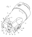
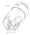
- the routing cutter is symmetrical about a central axis on which it rotates in the arrowed direction and comprises a generally cylindrical body 2 having a pair of diametrically opposed flutes 4 extending rearwards from a forward end of the body.
- a diametrically opposed pair of shorter hollows 6 are formed in the forward end of the body, between the flutes 4.
- the flutes and hollows may be directed axially or helically to the rotary axis.
- the forward end of the body is formed by facets 8 that are inclined axially rearwards from their radially outward ends.
Landscapes
- Engineering & Computer Science (AREA)
- Mechanical Engineering (AREA)
- Milling Processes (AREA)
Abstract
Claims (10)
- Fraise à défoncer comprenant un corps rotatif (2) pourvu d'une pluralité de lames rapportées (14, 28), lesdites lames rapportées comprenant une première arête tranchante qui fait saillie radialement depuis la périphérie dudit corps (2) et une seconde arête tranchante qui fait saillie depuis une extrémité axiale avant dudit corps (2) inclinée radialement vers l'intérieur et vers l'arrière dudit corps (2), lesdites lames rapportées étant situées en des positions angulairement espacées par rapport à un axe de rotation central dudit corps (2) et décrivant des enveloppes de coupe qui se croisent ou se chevauchent lors de la rotation dudit corps (2) autour dudit axe, caractérisée en ce que,a) la fraise comprend au moins une lame rapportée latérale (14) ayant la première arête tranchante (22), et au moins une lame rapportée terminale (28) ayant la seconde arête tranchante (38), etb) ladite au moins une lame rapportée latérale (14) étant fixée audit corps de fraisage (2) par des moyens de serrage (20) qui s'étendent vers l'intérieur à travers une face radialement extérieure de ladite lame rapportée latérale vers l'arrière de son arête tranchante.
- Fraise selon la revendication 1, dans laquelle ledit au moins un élément de fraisage latéral (14) est pourvu d'une arête tranchante qui agit sur une région radialement extérieure par rapport à l'extrémité axiale avant du corps de fraisage.
- Fraise selon la revendication 2, dans laquelle ladite arête tranchante terminale comprend une arête tranchante dirigée vers l'arrière continuant depuis son extrémité radialement intérieure, ladite arête tranchante dirigée vers l'arrière ayant une enveloppe de rotation chevauchant une arête tranchante de ladite au moins une lame rapportée terminale (28).
- Fraise selon l'une quelconque des revendications 1 à 3, dans laquelle les lames rapportées sont maintenues contre des faces respectives du corps de fraisage (2) qui s'étendant au moins approximativement tangentiellement par rapport à leur direction de rotation.
- Fraise selon l'une quelconque des revendications précédentes, dans laquelle les lames rapportées de fraisage (14, 28) sont remplaçables et indexables.
- Fraise selon l'une quelconque des revendications 1 à 5, dans laquelle les lames rapportées (14, 28) ont une forme allongée et une coupe transversale sensiblement uniforme, ladite au moins une lame rapportée latérale (14) ayant son axe longitudinal parallèle à l'axe de rotation de l'outil et ladite au moins une lame rapportée terminale (28) ayant son axe longitudinal incliné obliquement vers le haut en direction du centre de l'outil.
- Fraise selon l'une quelconque des revendications 1 à 6, dans laquelle lesdites première et seconde lames rapportées du groupe, ou de chaque groupe, sont situées aux côtés postérieurs de cavités radialement extérieures respectives dans le corps de l'outil.
- Fraise selon l'une quelconque des revendications 1 à 7, ayant une pluralité desdites lames rapportées latérales (14) équi-réparties angulairement par rapport à l'axe de rotation central et à des positions axiales et radiales correspondantes.
- Fraise selon la revendication 1, comprenant un corps outil (2) rotatif autour d'un axe longitudinal et supportant au moins un groupe d'au moins deux lames rapportées de fraisage remplaçables, une première lame rapportée (14) du groupe, ou de chacun desdits groupes, à la périphérie extérieure du corps ayant une arête tranchante fait saillie radialement et axialement du corps, ladite première lame rapportée étant fixée au corps outil par des moyens de serrage (20) s'étendant vers l'intérieur dans ledit corps depuis une ouverture (21) dans la lame rapportée espacée vers l'arrière depuis une face avant de la lame rapportée, ladite première lame rapportée faisant saillie radialement vers l'extérieur au-delà d'une seconde lame rapportée du groupe à l'extrémité avant du corps, ladite seconde lame rapportée (28) ayant une arête tranchante (38) qui fait saillie vers l'avant depuis le corps et est inclinée vers l'arrière en direction de l'axe de rotation, ladite seconde lame rapportée (28) s'étendant radialement vers l'intérieur au-delà de l'arête tranchante de ladite première lame rapportée, lesdites première et seconde lames rapportées du groupe, ou, de chacun desdits groupes de lames rapportées, étant angulairement espacées les unes des autres relativement à l'axe de rotation de l'outil.
- Fraise selon la revendication 9, dans laquelle une pluralité desdits groupes de lames rapportées est prévue, lesdits groupes étant montés sur le corps de l'outil (2) suivant un arrangement de rotation symétrique relativement audit axe de rotation du corps (2).
Applications Claiming Priority (5)
| Application Number | Priority Date | Filing Date | Title |
|---|---|---|---|
| GBGB9526197.0A GB9526197D0 (en) | 1995-12-21 | 1995-12-21 | Rotary cutting tools |
| GB9526197 | 1995-12-21 | ||
| GB9623170A GB2308325B (en) | 1995-12-21 | 1996-11-06 | Rotary cutting tools |
| GB9623170 | 1996-11-06 | ||
| PCT/SE1996/001643 WO1997023323A1 (fr) | 1995-12-21 | 1996-12-12 | Outils de coupe tournants |
Publications (2)
| Publication Number | Publication Date |
|---|---|
| EP0868244A1 EP0868244A1 (fr) | 1998-10-07 |
| EP0868244B1 true EP0868244B1 (fr) | 2002-02-27 |
Family
ID=26308356
Family Applications (1)
| Application Number | Title | Priority Date | Filing Date |
|---|---|---|---|
| EP96943429A Expired - Lifetime EP0868244B1 (fr) | 1995-12-21 | 1996-12-12 | Outils de coupe tournants |
Country Status (5)
| Country | Link |
|---|---|
| US (1) | US5984592A (fr) |
| EP (1) | EP0868244B1 (fr) |
| JP (1) | JP2000502958A (fr) |
| DE (1) | DE69619545T2 (fr) |
| WO (1) | WO1997023323A1 (fr) |
Cited By (1)
| Publication number | Priority date | Publication date | Assignee | Title |
|---|---|---|---|---|
| CN105798338A (zh) * | 2016-05-31 | 2016-07-27 | 成都恒成工具股份有限公司 | 一种机床用刀具 |
Families Citing this family (21)
| Publication number | Priority date | Publication date | Assignee | Title |
|---|---|---|---|---|
| SE512736C2 (sv) * | 1997-06-10 | 2000-05-08 | Seco Tools Ab | Planfräsningsverktyg |
| IL125298A (en) * | 1998-07-10 | 2001-10-31 | Iscar Ltd | Rotary cutting tool |
| DE10058226B4 (de) * | 2000-11-17 | 2014-09-04 | MAPAL Fabrik für Präzisionswerkzeuge Dr. Kress KG | Werkzeug zur spanabtragenden Bearbeitung von Bohrungsoberflächen |
| US6585527B2 (en) * | 2001-05-31 | 2003-07-01 | Samtec, Inc. | Compliant connector for land grid array |
| IL150783A0 (en) * | 2001-10-16 | 2003-02-12 | Iscar Ltd | Cutting tool and cutting insert therefor |
| ITMI20020294A1 (it) * | 2002-02-14 | 2003-08-14 | Livio Mina | Inserto quadrilatero per frese con angolo radiale dei taglienti negatico per la fresatura tridimensionale dal pieno |
| US6991409B2 (en) * | 2002-12-24 | 2006-01-31 | Niagara Cutter | Rotary cutting tool |
| SE526234C2 (sv) * | 2003-03-12 | 2005-08-02 | Sandvik Intellectual Property | Roterbart skärverktyg samt skär med snedställd planfasegg |
| US7189030B2 (en) | 2003-05-09 | 2007-03-13 | Kennametal Inc. | Cutting tool |
| USD541320S1 (en) * | 2004-06-21 | 2007-04-24 | Sandvik Intellectual Property Ab | Combination tool for chip forming machining |
| USD541321S1 (en) * | 2004-06-21 | 2007-04-24 | Sandvik Intellectual Property Ab | Combination tool for chip forming machining |
| SE528557C2 (sv) * | 2004-12-02 | 2006-12-12 | Sandvik Intellectual Property | Verktyg för spånavskiljande bearbetning för olika typ av bearbetning där skären för svarvning är axiellt förskjutna |
| JP2007069268A (ja) * | 2005-09-02 | 2007-03-22 | Sumitomo Electric Hardmetal Corp | スローアウェイ式工具 |
| IL174720A (en) * | 2006-04-02 | 2010-04-15 | Alexander Khina | Cutting tool |
| US7546786B2 (en) * | 2006-04-04 | 2009-06-16 | Kennametal Inc. | Toolholder with chip ejection segment thereupon |
| US20070297864A1 (en) * | 2006-06-23 | 2007-12-27 | De Boer Tools Inc. | Fluted Rotary Cutting Tool |
| DE502008003374D1 (de) * | 2007-09-04 | 2011-06-09 | Mapal Fab Praezision | Reibahle |
| DE102011117148B4 (de) | 2011-10-28 | 2022-05-05 | Kennametal Inc. | Rotationswerkzeug sowie Verfahren zum Herstellen eines Rotationswerkzeuges sowie eines Schneideinsatzes |
| EP2596889B1 (fr) * | 2011-11-23 | 2017-04-26 | Sandvik Intellectual Property AB | Plaquette de coupe et fraise |
| US9527142B2 (en) * | 2013-02-19 | 2016-12-27 | Iscar, Ltd. | High speed milling tool and tangential ramping milling insert therefor |
| US11529691B2 (en) * | 2019-12-02 | 2022-12-20 | Kennametal Inc. | Rotary cutting tool with hybrid cutting insert design |
Family Cites Families (13)
| Publication number | Priority date | Publication date | Assignee | Title |
|---|---|---|---|---|
| US3733665A (en) * | 1971-02-22 | 1973-05-22 | Pneumo Dynamics Corp | Rotary cutting tool |
| US4300862A (en) * | 1979-09-05 | 1981-11-17 | Dijet Industrial Co., Ltd. | End milling tool |
| CH642291A5 (fr) * | 1981-05-20 | 1984-04-13 | Stellram Sa | Fraise a percer-rainurer. |
| DE3209821A1 (de) * | 1982-03-18 | 1983-09-22 | Montanwerke Walter GmbH, 7400 Tübingen | Wendeplattenfraeser |
| GB2190863B (en) * | 1984-09-14 | 1988-07-06 | Sandvik Ltd | Replaceable cutting tip |
| SE455676B (sv) * | 1984-11-12 | 1988-08-01 | Sandvik Ab | Korthalsborr, samt sker derfor |
| GB8602971D0 (en) * | 1986-02-06 | 1986-03-12 | Marwin Cutting Tools Ltd | Tool formation |
| US4789273A (en) * | 1987-03-02 | 1988-12-06 | General Motors Of Canada Ltd. | Milling cutter |
| DE3831535A1 (de) * | 1987-09-16 | 1989-03-30 | Mitsubishi Metal Corp | Stirnfraeser |
| US4995767A (en) * | 1988-10-11 | 1991-02-26 | North American Products, Corp. | Face milling cutter with indexable inserts |
| GB8916263D0 (en) * | 1989-07-15 | 1989-08-31 | Technicut Limited | Router type cutter |
| US4993891A (en) * | 1990-02-20 | 1991-02-19 | General Motors Corporation | Milling cutter with grinding inserts |
| SE467727B (sv) * | 1991-01-28 | 1992-09-07 | Sandvik Ab | Borr med minst tvaa skaer, samt med symmetrisk borrspets och olika laanga skaereggar |
-
1996
- 1996-12-12 EP EP96943429A patent/EP0868244B1/fr not_active Expired - Lifetime
- 1996-12-12 JP JP09523559A patent/JP2000502958A/ja not_active Ceased
- 1996-12-12 WO PCT/SE1996/001643 patent/WO1997023323A1/fr not_active Ceased
- 1996-12-12 DE DE69619545T patent/DE69619545T2/de not_active Expired - Lifetime
- 1996-12-19 US US08/769,447 patent/US5984592A/en not_active Expired - Lifetime
Cited By (1)
| Publication number | Priority date | Publication date | Assignee | Title |
|---|---|---|---|---|
| CN105798338A (zh) * | 2016-05-31 | 2016-07-27 | 成都恒成工具股份有限公司 | 一种机床用刀具 |
Also Published As
| Publication number | Publication date |
|---|---|
| DE69619545D1 (de) | 2002-04-04 |
| WO1997023323A1 (fr) | 1997-07-03 |
| EP0868244A1 (fr) | 1998-10-07 |
| DE69619545T2 (de) | 2002-10-10 |
| JP2000502958A (ja) | 2000-03-14 |
| US5984592A (en) | 1999-11-16 |
Similar Documents
| Publication | Publication Date | Title |
|---|---|---|
| EP0868244B1 (fr) | Outils de coupe tournants | |
| KR100480521B1 (ko) | 공작물재료제거공구및언더컷홈형성방법 | |
| CN1612789B (zh) | 刀具和夹具 | |
| US3940835A (en) | Slotting cutter and cutting insert therefor | |
| JPS639927B2 (fr) | ||
| US6224299B1 (en) | Tool with straight inserts for providing helical cutting action | |
| JPS6110887Y2 (fr) | ||
| KR970006957B1 (ko) | 고속 버니싱드릴(High speed burnishing drill) | |
| US6431799B1 (en) | Slotting cutter | |
| US6497537B1 (en) | Slotting cutter with cartridge assembly | |
| GB2079656A (en) | Rotary cutting tools with plural cutting blades | |
| GB2308325A (en) | Rotary cutting tools | |
| US20010031181A1 (en) | Indexable drill and cutting inserts therefor | |
| JP3036343B2 (ja) | エンドミル | |
| JP2586463B2 (ja) | スロ−アウエイ式カツタ− | |
| GB2164283A (en) | Slotting cutter and removable tip | |
| US4712952A (en) | Drill for generating of holes in a work piece | |
| GB2157989A (en) | Rotary cutting tool | |
| JP7596716B2 (ja) | ドリル | |
| JPS6365450B2 (fr) | ||
| JPS63120010A (ja) | スロ−アウエイ式カツタ− | |
| JP2001009627A (ja) | スローアウェイ式カッタ | |
| JPS5850807B2 (ja) | スロ−アウエイカツタ | |
| JP2001232513A (ja) | スローアウェイ式カッターおよびスローアウェイチップ | |
| JPH0443727B2 (fr) |
Legal Events
| Date | Code | Title | Description |
|---|---|---|---|
| PUAI | Public reference made under article 153(3) epc to a published international application that has entered the european phase |
Free format text: ORIGINAL CODE: 0009012 |
|
| 17P | Request for examination filed |
Effective date: 19980622 |
|
| AK | Designated contracting states |
Kind code of ref document: A1 Designated state(s): DE FR IT SE |
|
| 17Q | First examination report despatched |
Effective date: 20010213 |
|
| GRAG | Despatch of communication of intention to grant |
Free format text: ORIGINAL CODE: EPIDOS AGRA |
|
| GRAG | Despatch of communication of intention to grant |
Free format text: ORIGINAL CODE: EPIDOS AGRA |
|
| GRAH | Despatch of communication of intention to grant a patent |
Free format text: ORIGINAL CODE: EPIDOS IGRA |
|
| GRAH | Despatch of communication of intention to grant a patent |
Free format text: ORIGINAL CODE: EPIDOS IGRA |
|
| GRAA | (expected) grant |
Free format text: ORIGINAL CODE: 0009210 |
|
| AK | Designated contracting states |
Kind code of ref document: B1 Designated state(s): DE FR IT SE |
|
| REF | Corresponds to: |
Ref document number: 69619545 Country of ref document: DE Date of ref document: 20020404 |
|
| PG25 | Lapsed in a contracting state [announced via postgrant information from national office to epo] |
Ref country code: SE Free format text: LAPSE BECAUSE OF FAILURE TO SUBMIT A TRANSLATION OF THE DESCRIPTION OR TO PAY THE FEE WITHIN THE PRESCRIBED TIME-LIMIT Effective date: 20020527 |
|
| ET | Fr: translation filed | ||
| PLBE | No opposition filed within time limit |
Free format text: ORIGINAL CODE: 0009261 |
|
| STAA | Information on the status of an ep patent application or granted ep patent |
Free format text: STATUS: NO OPPOSITION FILED WITHIN TIME LIMIT |
|
| 26N | No opposition filed |
Effective date: 20021128 |
|
| REG | Reference to a national code |
Ref country code: FR Ref legal event code: TP |
|
| REG | Reference to a national code |
Ref country code: FR Ref legal event code: TP |
|
| PGFP | Annual fee paid to national office [announced via postgrant information from national office to epo] |
Ref country code: DE Payment date: 20141209 Year of fee payment: 19 |
|
| PGFP | Annual fee paid to national office [announced via postgrant information from national office to epo] |
Ref country code: FR Payment date: 20141208 Year of fee payment: 19 |
|
| PGFP | Annual fee paid to national office [announced via postgrant information from national office to epo] |
Ref country code: IT Payment date: 20141210 Year of fee payment: 19 |
|
| REG | Reference to a national code |
Ref country code: DE Ref legal event code: R119 Ref document number: 69619545 Country of ref document: DE |
|
| REG | Reference to a national code |
Ref country code: FR Ref legal event code: ST Effective date: 20160831 |
|
| PG25 | Lapsed in a contracting state [announced via postgrant information from national office to epo] |
Ref country code: DE Free format text: LAPSE BECAUSE OF NON-PAYMENT OF DUE FEES Effective date: 20160701 |
|
| PG25 | Lapsed in a contracting state [announced via postgrant information from national office to epo] |
Ref country code: FR Free format text: LAPSE BECAUSE OF NON-PAYMENT OF DUE FEES Effective date: 20151231 |
|
| PG25 | Lapsed in a contracting state [announced via postgrant information from national office to epo] |
Ref country code: IT Free format text: LAPSE BECAUSE OF NON-PAYMENT OF DUE FEES Effective date: 20151212 |