EP0868593B1 - Vorrichtung und verfahren zum heben und senken eines kolbens in einer kolben-zylinder einheit in einem bohrmast - Google Patents
Vorrichtung und verfahren zum heben und senken eines kolbens in einer kolben-zylinder einheit in einem bohrmast Download PDFInfo
- Publication number
- EP0868593B1 EP0868593B1 EP96943394A EP96943394A EP0868593B1 EP 0868593 B1 EP0868593 B1 EP 0868593B1 EP 96943394 A EP96943394 A EP 96943394A EP 96943394 A EP96943394 A EP 96943394A EP 0868593 B1 EP0868593 B1 EP 0868593B1
- Authority
- EP
- European Patent Office
- Prior art keywords
- piston
- cylinder
- port
- chamber
- lowering
- Prior art date
- Legal status (The legal status is an assumption and is not a legal conclusion. Google has not performed a legal analysis and makes no representation as to the accuracy of the status listed.)
- Expired - Lifetime
Links
- 238000000034 method Methods 0.000 title claims description 4
- 239000012530 fluid Substances 0.000 claims description 24
- 230000008878 coupling Effects 0.000 claims 4
- 238000010168 coupling process Methods 0.000 claims 4
- 238000005859 coupling reaction Methods 0.000 claims 4
- 238000006073 displacement reaction Methods 0.000 description 3
- 238000010276 construction Methods 0.000 description 1
- 238000005553 drilling Methods 0.000 description 1
- 230000000694 effects Effects 0.000 description 1
Images





Classifications
-
- E—FIXED CONSTRUCTIONS
- E21—EARTH OR ROCK DRILLING; MINING
- E21B—EARTH OR ROCK DRILLING; OBTAINING OIL, GAS, WATER, SOLUBLE OR MELTABLE MATERIALS OR A SLURRY OF MINERALS FROM WELLS
- E21B19/00—Handling rods, casings, tubes or the like outside the borehole, e.g. in the derrick; Apparatus for feeding the rods or cables
- E21B19/02—Rod or cable suspensions
-
- E—FIXED CONSTRUCTIONS
- E21—EARTH OR ROCK DRILLING; MINING
- E21B—EARTH OR ROCK DRILLING; OBTAINING OIL, GAS, WATER, SOLUBLE OR MELTABLE MATERIALS OR A SLURRY OF MINERALS FROM WELLS
- E21B15/00—Supports for the drilling machine, e.g. derricks or masts
-
- E—FIXED CONSTRUCTIONS
- E21—EARTH OR ROCK DRILLING; MINING
- E21B—EARTH OR ROCK DRILLING; OBTAINING OIL, GAS, WATER, SOLUBLE OR MELTABLE MATERIALS OR A SLURRY OF MINERALS FROM WELLS
- E21B19/00—Handling rods, casings, tubes or the like outside the borehole, e.g. in the derrick; Apparatus for feeding the rods or cables
- E21B19/08—Apparatus for feeding the rods or cables; Apparatus for increasing or decreasing the pressure on the drilling tool; Apparatus for counterbalancing the weight of the rods
- E21B19/086—Apparatus for feeding the rods or cables; Apparatus for increasing or decreasing the pressure on the drilling tool; Apparatus for counterbalancing the weight of the rods with a fluid-actuated cylinder
Definitions
- the present invention relates to a hoisting apparatus for a derrick, according to the pre-characterising portion of claim 1. It also relates to a derrick and a method therefor.
- a derrick structure developed by the present inventor in 1987, that has shown great promise is the RamRigTM concept.
- Two or more hydraulic piston/cylinder arrangements are used in the derrick for raising and lowering the drill string.
- the cylinders operate between the drill floor and a yoke which travels on guide rails in the derrick itself.
- the advantages of this concept are numerous, some of the most important being that it is possible to place the drill floor at a higher level than the platform floor, that a derrick having significantly lower air resistance can be constructed, and that the most expensive components of the derrick attain higher safety and a longer lifetime.
- the object of the present invention is to solve important, practical problems in the realization of the RamRigTM concept. This object is achieved by means of the features apparent from the characterizing clause of the subsequently disclosed claim 1.
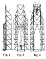
- Figure 1 shows a derrick 1 positioned on a drill floor 2.
- the drill floor is positioned at a higher level than the platform floor 3, so that the pipe handling equipment 4 can be placed, in the main, between the platform floor 3 and the drill floor 2.
- the derrick 1 is substantially gantry-shaped, with gantry legs 5, 6.
- Guide rails 7 for a yoke 8 and a top-drive 9 run along each gantry leg 5, 6.
- Hydraulic piston/cylinder arrangements 10, 11 are positioned so that they extend along each gantry leg 5, 6 and operate between the drill floor 2 and the yoke 8, for moving the yoke 8 vertically along the guide rails 7.
- the yoke 8 is provided with a plurality of sheaves 12, preferably four, for running wire lines 13.
- the wire lines 13 run from the drill floor 2 along each gantry leg 5, 6, over the sheaves 12 and down to the top drive 9.
- the yoke 8 When the pistons in the piston/cylinder arrangement are extended, the yoke 8 is lifted along the guide rails 7 up to the top of the derrick 1. The top drive is then lifted, as a result of the exchange created by the wire lines 13 being run over the sheaves 12, from its position adjacent to the drill floor 2 to a position directly below the yoke 8. The height to which the top drive 9 is lifted is thus the double of that to which the yoke 8 is lifted.
- wire lines 13 There may, for example, be as much as eight wire lines 13 arranged in the lift means described above, where two and two are strung in their own separate tracks over the same sheave 12.
- Four sheaves are arranged in pairs at each end of the yoke 8.
- the wire lines 13 are thus arranged in two sets 13a and 13b, extending from attachment points 14a and 14b at the drill floor 2, over the sheaves 12 and down to the top drive 9.
- the attachment points 14a and 14b are horizontally spaced apart by a distance approximately like the length of the yoke 8.
- FIG. 5 the piston/cylinder arrangements 10, 11 are schematically illustrated.
- the yoke 8 is also shown, together with the sheaves 12 and the top drive 9.
- the drill floor 2 is also indicated. From the drill floor 2 each of the wire lines 13 runs over its own sheave 12 and down to the top drive 9.
- Each piston/cylinder arrangement 10, 11 consists of a cylinder and a piston 21 having a piston rod 22.
- the cylinder 20 is at one end attached to the drill floor 2, whereas the piston rod 22 is attached to the yoke 8.
- the piston 21 divides the cylinder into two chambers, a lower chamber 23 and an upper chamber 24.
- the lower chamber 23 is circular/cylindrical and only delimited by the walls of the cylinder 20 and the lower end surface 25 of the piston 21.
- the upper chamber 24 is also delimited by the walls of the cylinder 20, but is in addition delimited by the piston rod 22 and the upper annular surface 26 of the piston 21. It will thus be seen that hydraulic fluid in the lower chamber 23 has a larger operating surface with respect to the piston 21 than hydraulic fluid in the upper chamber 24, since the lower end surface 25 of the piston is larger than its upper annular surface 26.
- the drive system which is here generally designated by reference numeral 30, consists of a reservoir 31, a feed pump 32 driven by a motor 33, one or more main pumps 34 driven by one or more motors 35, a control valve 36, an accumulator/valve plate 37, a cylinder valve 38 for each cylinder 20, one or more accumulators 39 and one or more pressure tanks 40.
- a line 43 leads from the reservoir 31, via the feed pump 38 to a third port c in the control valve 36.
- a line 44 leads to the accumulator/valve plate 37.
- a line 45 leads via a ramification 46, where the line 45 branches so as to create one line for each cylinder 20 leading into a port f in each cylinder valve 38.
- the line 44 which leads into a port g in the accumulator/valve plate 37, splits here into branches which lead from a number of ports h to the control valve 38 of each cylinder 20 into a port i for each control valve 36.
- the accumulators 39 are connected to the accumulator valve plate 37 via ports j. It must be understood that both ports h and ports j respectively may represent a plurality of ports or optionally one port branching outside the accumulator/valve plate 37.
- the accumulators 39 are connected to the pressure tanks 40 via a line 47.
- a line 48 connected with the upper chamber 24 of the cylinder 20, extends from a port k in each cylinder valve 38. From a port l in each cylinder valve a line 49 leads to the chamber 23 of the cylinder 20. A line 50 connects ports m in each cylinder valve 38.
- the piston/cylinder arrangements are extended for maximum thrust power, but at low velocity.
- the displacement volume of the main pump 34 is adjusted so that hydraulic fluid flows from the reservoir 31, via the feed pump 32 and the line 43, in through the port c in the control valve 36, out through the port b, through the line 42 via the main pump 34 and the line 41 to port a of the control valve 36, out through the port e, via the line 44 to port g of the accumulator valve plate and from this via the ports h to the ports i in the cylinder valves 38 and further out through the ports l and the lines 49 to the chamber 23 of the cylinder 20.
- Hydraulic fluid displaced from the chamber 24 of the cylinder 20, flows via the lines 48, via the cylinder valves 38 and the line 45 back to the control valve 36 and main pump 34.
- the ports j in the accumulator valve plate 37 are closed.
- the connection 50 between the ports m of the cylinder valves 38 is open, however, in order to ensure that there is equal pressure on the underside 25 of the pistons 21. In this mode the piston/cylinder arrangements 10, 11 would be extended at a comparatively low velocity, but with a relatively high thrust power.
- FIG 7 another mode is shown which, with respect to hydraulic fluid circulation, is quite in accordance with the mode shown in figure 6.
- the ports j in the accumulator valve plate 37 have been opened up so that the accumulators 39, which are influenced by pressure from pressure tanks 4 via the line 47, increase the pressure in the hydraulic fluid which flows through the line 44 to the lower chamber 23 of the cylinders 20.
- the velocity of the pistons 21 is then somewhat increased at the same time as the thrust power is maintained at a high level.
- FIG 8 a mode is shown where the travelling speed of the pistons 21 has been further increased. At the same time the thrust force is reduced.
- This mode is thus well suited for raising the unloaded top drive 9.
- the connection is opened between the ports i, k, l and m in the control valves 38, so that the lower chamber 23 and the upper chamber 24 of the cylinders 20 are short circuited.
- the hydraulic pressure acts on a differential area which is equal to the difference between the area of the underside 25 of the piston 21 and the top side 26 of the piston 21, i.e., the cross-sectional area of the piston rod 22.
- the piston 21 obtains a greater travelling speed at the same hydraulic pressure.
- the ports j in the accumulator valve plate 37 are closed so that the accumulators 39 do not function.
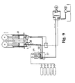
- FIG 9 a further mode is shown, where the ports j of the accumulator valve plate 37 are opened so that the accumulators 39 supply an additional pressure into the line 44.
- the connection between ports i, k and l in the cylinder valves 38 is open.
- the ports m may also be open in this mode, although this is not shown here.
- the travelling speed of the piston 21 will be further increased because of the increased pressure in the line 44.
- the thrust force will still be comparatively low, however.
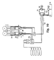
- FIG 10 there is shown a lowering mode at maximum load and controlled speed.
- the main pump 34 is now readjusted so that the hydraulic fluid flows into the pump through the line 41 and out of the pump through the line 42.
- the connection between the ports k of the lines 48 in the cylinder valves 38 and the port f of the line 45 in the cylinder valves 38 is open so that the hydraulic fluid flows into the upper chamber 24 of the cylinder.
- the connection between the port l and the port i in the cylinder valves 38 is open so that the hydraulic fluid in chamber 23 of the cylinder 20 flows out in the line 44. A part of the hydraulic fluid will flow back to the reservoir 31 for the very reason that the chamber 24 of the cylinder 20 has a smaller cross sectional area than the chamber 23.
- FIG 11 a lowering mode is shown where the lowering is carried out at up to maximum load and up to maximum velocity.
- the ports f, i, k and l in the cylinder valves 38 are connected with each other.
- hydraulic fluid can freely flow out of the chamber 23 of the cylinder 20. Some of this fluid will flow back to the cylinder and into the chamber 24, whereas the remainder will flow through the lines 44 and 45 and further, to the reservoir 31.
- the lowering speed can be controlled to a certain degree by means of the main pump 34, but because of the fact that the connection between the cylinder valves 38 and the reservoir 31 via the line 45 is completely open, it will be expedient to control the lowering speed by means of a throttling 51, which, as shown here, may lie in the connection between the port l and the ports f, i and k in the cylinder valves 38. This mode will be well suited for carrying out hard thrusts with the drill string, if the need should arise.
- Figure 12 shows a mode of operation where constant load is maintained during the movement of the piston/cylinder arrangements 10, 11.
- This mode is used, for example, for the drilling itself.
- the fluid flow goes back and forth in the system, and the displacement volume of the main pump 34 is adjusted in both directions in accordance with signals given from a load distributor (not shown).
- the connection between the ports f and k in the cylinder valve 38 is open, as is the connection between the ports i and l.
- the hydraulic fluid thus flows between the main pump 34 and the cylinder valve 38 via the line 44 and the line 45, respectively.
- the directions of the flow of fluid in these two lines will at all times be opposite to each other.
- a certain exchange of hydraulic fluid with the reservoir 31 will also occur, since the cross-sectional areas of the lower chamber 23 of the cylinder 20 and of the upper chamber 24 are different.
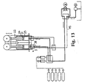
- Figure 13 shows a similar mode of operation, where the purpose is to maintain a constant load while the pistons 21 are moved. In this mode, however, a greater velocity is achieved with respect to the travel of the piston.
- the port f in the valve 38 is now closed, so that there no longer will be any fluid flow in the line 45.
- the ports i, k and l in the cylinder valve 38 are connected with each other, however.
- the area of piston 21 activity will be the differential area between the area of the lower surface 25 of the piston and the area of the upper annular surface 26 of the piston. This corresponds to the cross-sectional area of the piston rod 22. A faster move of the piston 21 will then be obtained even if the pressure in the system is unchanged.
Landscapes
- Engineering & Computer Science (AREA)
- Geology (AREA)
- Mining & Mineral Resources (AREA)
- Life Sciences & Earth Sciences (AREA)
- General Life Sciences & Earth Sciences (AREA)
- Fluid Mechanics (AREA)
- Mechanical Engineering (AREA)
- Environmental & Geological Engineering (AREA)
- Physics & Mathematics (AREA)
- Geochemistry & Mineralogy (AREA)
- Earth Drilling (AREA)
- Fluid-Pressure Circuits (AREA)
- Actuator (AREA)
- Forklifts And Lifting Vehicles (AREA)
- Load-Engaging Elements For Cranes (AREA)
Claims (9)
- Hebevorrichtung für einen Bohrturm, die zwei oder mehr im wesentlichen vertikale Hydraulikkolben/Zylinder-Anordnungen (10, 11) zum Anheben und Absenken eines Jochs (8) umfaßt, das so ausgeführt ist, daß es sich auf Führungsschienen (7) weiterbewegen kann, wobei jede der Hydraulikkolben/Zylinder-Anordnungen (10, 11) einen Zylinder (20), einen Kolben (21) mit einer Kolbenstange (22), wobei der Kolben den Zylinder in eine untere Zylinderkammer (23) und eine obere Zylinderkammer (24) unterteilt, wobei die Oberfläche des der unteren Zylinderkammer (23) zugewandten Kolbens (21) anders als die Oberfläche des der oberen Zylinderkammer (24) zugewandten Kolbens (21) ausgeführt ist, wobei die Kolbenstange (22) mit dem Joch (8) verbunden werden kann, sowie ein Hydrauliksystem (30) für den Betrieb der Kolben/Zylinder-Anordnungen (10, 11) umfaßt, wobei das Hydrauliksystem mindestens eine Hauptpumpe (34) mit Einlaß- und Auslaßöffnungen zur Zuleitung von Hydraulikfluiddruck an jede Kolben/Zylinder-Anordnung (10, 11), Ventile (36, 37, 38) zur Steuerung von Hydraulikddruck zur unteren Zylinderkammer (23) bzw. zur oberen Zylinderkammer (24) umfaßt, dadurch gekennzeichnet, daß mindestens eines der Ventile ein Zylindersteuerungsventil (38) ist, das so ausgeführt ist, daß es die Verbindung zwischen Öffnungen (f, i, k, l) im Ventil (38) öffnet und schließt, um in den folgenden Betriebsarten eine Verbindung herzustellen zwischenjeder der oberen und der unteren Zylinderkammer (23, 24) und der Auslaß- bzw. der Einlaßöffnung der Hauptpumpe (34) zum normalen Anheben und Absenken des Jochs (8),jeder der oberen und der unteren Zylinderkammer (23, 24) und der Einlaßöffnung in der Hauptpumpe (34) sowie wahlweise direkt zwischen den Kammern (23, 24) und einem Reservoir (31) zum raschen Absenken des Jochs (8) oderjeder der oberen und der unteren Zylinderkammer (23, 24) und der Auslaßöffnung der Hauptpumpe zum raschen Anheben des Jochs (8).
- Hebevorrichtung nach Anspruch 1, bei der das Hydrauliksystem (30) einen oder mehrere Sammler (39) umfaßt, die so ausgeführt sind, daß während des Anhebens des Kolbens (21) eine Verbindung mit einer ersten Leitung (44) hergestellt wird, um der unteren Kammer (23) Hydraulikfluid zuzuführen, um die Kammer (23) mit zusätzlichem Druck zu versorgen, so daß sich der Kolben (21) rascher bewegt.
- Hebevorrichtung nach Anspruch 2, bei der die Sammler (39) so ausgeführt sind, daß während des Absenkens des Kolbens (21) eine Verbindung mit der Leitung (44) hergestellt wird, so daß in der unteren Kammer erzeugter Hydraulikdruck die Sammler (39) beaufschlagt.
- Hebevorrichtung nach Anspruch 2 oder 3, bei der das Ventil (38) eine erste Öffnung (f) zur Verbindung mit einer Leitung (45), um Hydraulikfluid zu und von einer Seite der Hauptpumpe (34) zu befördern, eine zweite Öffnung (i) zur Verbindung mit der ersten Leitung (44), um Hydraulikfluid zu und von der anderen Seite der Hauptpumpe (34) zu befördern, eine dritte Öffnung (k) zur Verbindung mit einer zweiten Leitung (48), um Hydraulikfluid zu und von der oberen Kammer (24) zu befördern, sowie eine vierte Öffnung (l) zur Verbindung mit einer dritten Leitung (49) umfaßt, um Hydraulikfluid zu und von der unteren Kammer (23) zu befördern, dadurch gekennzeichnet, daß während des normalen Anhebens und Absenkens des Kolbens (21) die erste Öffnung (f) mit der dritten Öffnung (k) und die zweite Öffnung (i) mit der vierten Öffnung (l) verbunden ist, und daß während des raschen Anhebens oder Absenkens die dritte Öffnung (k) und die vierte Öffnung (l) sowie die erste Öffnung (f) und/oder die zweite Öffnung (i) miteinander verbunden sind.
- Hebevorrichtung nach Anspruch 4, bei der das Zylindersteuerungsventil (38) auch eine fünfte Öffnung (m) umfaßt, die so ausgeführt ist, daß sie mit einer entsprechenden Öffnung (m) in einem anderen oder in mehreren anderen Zylindersteuerungsventil(en) (38) über eine vierte Leitung (50) verbunden werden kann und weiterhin in ihrer Verbindung mit der vierten Öffnung (l) nicht eingeschränkt ist, um so die Möglichkeit zu bieten, die Druckdifferenzen zwischen den unteren Kammern (23) der verschiedenen Zylinder (20) auszugleichen.
- Hebevorrichtung nach Anspruch 4 oder 5, bei der die Verbindung zwischen der dritten Leitung (49), die sich von der unteren Kammer (23) aus erstreckt, und der ersten Leitung (44), die zur anderen Seite der Hauptpumpe (34) führt, eine Drossel (51) umfaßt.
- Bohrturm, der eine Hebevorrichtung nach einem der vorhergehenden Ansprüche umfaßt, bei der die Hebevorrichtung die Führungsschienen umfaßt.
- Verfahren zum Anheben und Absenken eines Kolbens (21) in zwei oder mehr im wesentlichen vertikalen Kolben/Zylinder-Anordnungen (10, 11) zum Zwecke des Anhebens und Absenkens eines Jochs (8), das sich auf Führungsschienen (7) in einem Bohrturm weiterbewegt, dadurch gekennzeichnet, daß zum normalen Anheben oder Absenken des Kolbens (21) eine untere Zylinderkammer (23) jeder Kolben/Zylinder-Anordnung (10, 11) mit einer ersten Seite einer Hauptpumpe (34) verbunden ist, während eine obere Zylinderkammer (24) jeder der Kolben/Zylinder-Anordnungen (10, 11) mit der anderen Seite der Pumpe verbunden ist, daß zum raschen Anheben des Kolbens (21) die untere Kammer und die obere Kammer (23, 24) miteinander und mit der Auslaßseite der Hauptpumpe (34) verbunden sind, und daß zum raschen Absenken des Kolbens (21) die untere Kammer und die obere Kammer (23, 24) miteinander und mit der Einlaßseite der Hauptpumpe (34) und/oder direkt mit einem Reservoir (31) verbunden sind.
- Verfahren nach Anspruch 8, bei dem ein oder mehrere Sammler (39) so mit der unteren Kammer (23) verbunden ist bzw. sind, daß während des Anhebens des Kolbens (21) zusätzlicher Druck zugeführt wird, und daß die Sammler (39) während des Absenkens des Kolbens (21) zur Beaufschlagung der Sammler mit der unteren Kammer (23) verbunden bleiben.
Applications Claiming Priority (3)
| Application Number | Priority Date | Filing Date | Title |
|---|---|---|---|
| NO955271A NO302047B1 (no) | 1995-12-22 | 1995-12-22 | Anordning ved boretårn omfattende drivanordning for stempel-/sylinderarrangement |
| NO955271 | 1995-12-22 | ||
| PCT/NO1996/000294 WO1997023706A1 (en) | 1995-12-22 | 1996-12-18 | Apparatus and method for raising and lowering a piston in a piston-cylinder arrangement in a derrick |
Publications (2)
| Publication Number | Publication Date |
|---|---|
| EP0868593A1 EP0868593A1 (de) | 1998-10-07 |
| EP0868593B1 true EP0868593B1 (de) | 2004-03-03 |
Family
ID=19898876
Family Applications (1)
| Application Number | Title | Priority Date | Filing Date |
|---|---|---|---|
| EP96943394A Expired - Lifetime EP0868593B1 (de) | 1995-12-22 | 1996-12-18 | Vorrichtung und verfahren zum heben und senken eines kolbens in einer kolben-zylinder einheit in einem bohrmast |
Country Status (9)
| Country | Link |
|---|---|
| EP (1) | EP0868593B1 (de) |
| JP (1) | JP2000502765A (de) |
| KR (1) | KR19990076668A (de) |
| AT (1) | ATE261054T1 (de) |
| AU (1) | AU1213397A (de) |
| CA (1) | CA2240582C (de) |
| DE (1) | DE69631788D1 (de) |
| NO (1) | NO302047B1 (de) |
| WO (1) | WO1997023706A1 (de) |
Cited By (1)
| Publication number | Priority date | Publication date | Assignee | Title |
|---|---|---|---|---|
| CN106321534A (zh) * | 2016-09-21 | 2017-01-11 | 中国石油大学(华东) | 海洋浮式钻井游车大钩升沉补偿装置 |
Families Citing this family (3)
| Publication number | Priority date | Publication date | Assignee | Title |
|---|---|---|---|---|
| ITTO20060536A1 (it) * | 2006-07-20 | 2008-01-21 | Drillmec Spa | Unita' di perforazione. |
| KR100654207B1 (ko) * | 2006-09-11 | 2006-12-06 | (주)수호산업개발 | 굴삭기에 장착되는 암반천공장치의 유압회로 시스템 |
| CN108035917B (zh) * | 2017-12-12 | 2019-07-09 | 中国石油大学(华东) | 一种液气蓄能装置用隔离阀 |
Family Cites Families (1)
| Publication number | Priority date | Publication date | Assignee | Title |
|---|---|---|---|---|
| GB106955A (en) * | 1916-12-22 | 1917-06-14 | Napoleon Rinfrett | An Improved Anti-skidding Device for Wheel Tyres. |
-
1995
- 1995-12-22 NO NO955271A patent/NO302047B1/no not_active IP Right Cessation
-
1996
- 1996-12-18 KR KR1019980704780A patent/KR19990076668A/ko not_active Ceased
- 1996-12-18 WO PCT/NO1996/000294 patent/WO1997023706A1/en not_active Ceased
- 1996-12-18 CA CA002240582A patent/CA2240582C/en not_active Expired - Fee Related
- 1996-12-18 EP EP96943394A patent/EP0868593B1/de not_active Expired - Lifetime
- 1996-12-18 AT AT96943394T patent/ATE261054T1/de not_active IP Right Cessation
- 1996-12-18 AU AU12133/97A patent/AU1213397A/en not_active Abandoned
- 1996-12-18 DE DE69631788T patent/DE69631788D1/de not_active Expired - Lifetime
- 1996-12-18 JP JP9523532A patent/JP2000502765A/ja active Pending
Cited By (2)
| Publication number | Priority date | Publication date | Assignee | Title |
|---|---|---|---|---|
| CN106321534A (zh) * | 2016-09-21 | 2017-01-11 | 中国石油大学(华东) | 海洋浮式钻井游车大钩升沉补偿装置 |
| CN106321534B (zh) * | 2016-09-21 | 2018-02-16 | 中国石油大学(华东) | 海洋浮式钻井游车大钩升沉补偿装置 |
Also Published As
| Publication number | Publication date |
|---|---|
| AU1213397A (en) | 1997-07-17 |
| WO1997023706A1 (en) | 1997-07-03 |
| KR19990076668A (ko) | 1999-10-15 |
| ATE261054T1 (de) | 2004-03-15 |
| CA2240582A1 (en) | 1997-07-03 |
| NO955271L (no) | 1997-06-23 |
| NO955271D0 (no) | 1995-12-22 |
| NO302047B1 (no) | 1998-01-12 |
| CA2240582C (en) | 2005-08-09 |
| DE69631788D1 (de) | 2004-04-08 |
| JP2000502765A (ja) | 2000-03-07 |
| EP0868593A1 (de) | 1998-10-07 |
Similar Documents
| Publication | Publication Date | Title |
|---|---|---|
| US3986564A (en) | Well rig | |
| US6094910A (en) | Apparatus and method for raising and lowering a piston in a piston cylinder arrangement in a derrick | |
| US4961316A (en) | Controlled electric pump drive for hydraulic lifting arrangement with gas spring in motor | |
| US6343662B2 (en) | Hydraulic drilling rig | |
| US20060277905A1 (en) | Hydraulic control device of industrial machinery | |
| US3719238A (en) | Compact rotary well drilling rig with hydraulic swivel pull down mechanism | |
| US5697457A (en) | No load derrick for drilling rig | |
| EP0567218A1 (de) | Teleskopische Armanordnung mit zwei mit einander verbundenen hydraulischen Stellgliedern für einen Schalengreiferbagger | |
| US10519725B2 (en) | Hydraulic multi-displacement hoisting cylinder system | |
| EP0868593B1 (de) | Vorrichtung und verfahren zum heben und senken eines kolbens in einer kolben-zylinder einheit in einem bohrmast | |
| CN108223467A (zh) | 用于全液压履带式反循环工程钻机的液压系统 | |
| US4730743A (en) | Hydraulically operated bridge crane | |
| US4796863A (en) | Dual cluster crown block | |
| US4585213A (en) | Well derrick | |
| US6422349B1 (en) | Hydrostatic displacement drive for lifting and lowering and holding loads, in particular for lifts | |
| CN1008641B (zh) | 步行坐底式钻井平台 | |
| US3511476A (en) | Sheave assembly for offshore drilling rigs | |
| GB2131890A (en) | Hydraulic well pump | |
| US4903443A (en) | Derrick having upper and lower crown block positions | |
| CN111075351A (zh) | 一种锚杆钻机系统 | |
| JP7715627B2 (ja) | 杭打機の油圧駆動装置 | |
| US11802447B2 (en) | Drilling rig with drawworks proximate to the operating side of the mast | |
| NO348338B1 (en) | Hoisting system and method of operation | |
| CN114875878A (zh) | 可双向输水的船闸输水系统阀门段布置结构 | |
| CN103225478B (zh) | 工程钻机液压式驱动系统 |
Legal Events
| Date | Code | Title | Description |
|---|---|---|---|
| PUAI | Public reference made under article 153(3) epc to a published international application that has entered the european phase |
Free format text: ORIGINAL CODE: 0009012 |
|
| 17P | Request for examination filed |
Effective date: 19980619 |
|
| AK | Designated contracting states |
Kind code of ref document: A1 Designated state(s): AT BE CH DE DK ES FI FR GB GR IE IT LI LU MC NL PT SE |
|
| 17Q | First examination report despatched |
Effective date: 20020301 |
|
| GRAH | Despatch of communication of intention to grant a patent |
Free format text: ORIGINAL CODE: EPIDOS IGRA |
|
| GRAS | Grant fee paid |
Free format text: ORIGINAL CODE: EPIDOSNIGR3 |
|
| GRAA | (expected) grant |
Free format text: ORIGINAL CODE: 0009210 |
|
| AK | Designated contracting states |
Kind code of ref document: B1 Designated state(s): AT BE CH DE DK ES FI FR GB GR IE IT LI LU MC NL PT SE |
|
| PG25 | Lapsed in a contracting state [announced via postgrant information from national office to epo] |
Ref country code: NL Free format text: LAPSE BECAUSE OF FAILURE TO SUBMIT A TRANSLATION OF THE DESCRIPTION OR TO PAY THE FEE WITHIN THE PRESCRIBED TIME-LIMIT Effective date: 20040303 Ref country code: LI Free format text: LAPSE BECAUSE OF FAILURE TO SUBMIT A TRANSLATION OF THE DESCRIPTION OR TO PAY THE FEE WITHIN THE PRESCRIBED TIME-LIMIT Effective date: 20040303 Ref country code: IT Free format text: LAPSE BECAUSE OF FAILURE TO SUBMIT A TRANSLATION OF THE DESCRIPTION OR TO PAY THE FEE WITHIN THE PRESCRIBED TIME-LIMIT;WARNING: LAPSES OF ITALIAN PATENTS WITH EFFECTIVE DATE BEFORE 2007 MAY HAVE OCCURRED AT ANY TIME BEFORE 2007. THE CORRECT EFFECTIVE DATE MAY BE DIFFERENT FROM THE ONE RECORDED. Effective date: 20040303 Ref country code: FR Free format text: LAPSE BECAUSE OF FAILURE TO SUBMIT A TRANSLATION OF THE DESCRIPTION OR TO PAY THE FEE WITHIN THE PRESCRIBED TIME-LIMIT Effective date: 20040303 Ref country code: FI Free format text: LAPSE BECAUSE OF FAILURE TO SUBMIT A TRANSLATION OF THE DESCRIPTION OR TO PAY THE FEE WITHIN THE PRESCRIBED TIME-LIMIT Effective date: 20040303 Ref country code: CH Free format text: LAPSE BECAUSE OF FAILURE TO SUBMIT A TRANSLATION OF THE DESCRIPTION OR TO PAY THE FEE WITHIN THE PRESCRIBED TIME-LIMIT Effective date: 20040303 Ref country code: BE Free format text: LAPSE BECAUSE OF FAILURE TO SUBMIT A TRANSLATION OF THE DESCRIPTION OR TO PAY THE FEE WITHIN THE PRESCRIBED TIME-LIMIT Effective date: 20040303 Ref country code: AT Free format text: LAPSE BECAUSE OF FAILURE TO SUBMIT A TRANSLATION OF THE DESCRIPTION OR TO PAY THE FEE WITHIN THE PRESCRIBED TIME-LIMIT Effective date: 20040303 |
|
| REG | Reference to a national code |
Ref country code: GB Ref legal event code: FG4D |
|
| REG | Reference to a national code |
Ref country code: CH Ref legal event code: EP |
|
| REG | Reference to a national code |
Ref country code: IE Ref legal event code: FG4D |
|
| REF | Corresponds to: |
Ref document number: 69631788 Country of ref document: DE Date of ref document: 20040408 Kind code of ref document: P |
|
| PG25 | Lapsed in a contracting state [announced via postgrant information from national office to epo] |
Ref country code: SE Free format text: LAPSE BECAUSE OF FAILURE TO SUBMIT A TRANSLATION OF THE DESCRIPTION OR TO PAY THE FEE WITHIN THE PRESCRIBED TIME-LIMIT Effective date: 20040603 Ref country code: GR Free format text: LAPSE BECAUSE OF FAILURE TO SUBMIT A TRANSLATION OF THE DESCRIPTION OR TO PAY THE FEE WITHIN THE PRESCRIBED TIME-LIMIT Effective date: 20040603 Ref country code: DK Free format text: LAPSE BECAUSE OF FAILURE TO SUBMIT A TRANSLATION OF THE DESCRIPTION OR TO PAY THE FEE WITHIN THE PRESCRIBED TIME-LIMIT Effective date: 20040603 |
|
| PG25 | Lapsed in a contracting state [announced via postgrant information from national office to epo] |
Ref country code: DE Free format text: LAPSE BECAUSE OF FAILURE TO SUBMIT A TRANSLATION OF THE DESCRIPTION OR TO PAY THE FEE WITHIN THE PRESCRIBED TIME-LIMIT Effective date: 20040604 |
|
| PG25 | Lapsed in a contracting state [announced via postgrant information from national office to epo] |
Ref country code: ES Free format text: LAPSE BECAUSE OF FAILURE TO SUBMIT A TRANSLATION OF THE DESCRIPTION OR TO PAY THE FEE WITHIN THE PRESCRIBED TIME-LIMIT Effective date: 20040614 |
|
| NLV1 | Nl: lapsed or annulled due to failure to fulfill the requirements of art. 29p and 29m of the patents act | ||
| REG | Reference to a national code |
Ref country code: CH Ref legal event code: PL |
|
| PG25 | Lapsed in a contracting state [announced via postgrant information from national office to epo] |
Ref country code: LU Free format text: LAPSE BECAUSE OF NON-PAYMENT OF DUE FEES Effective date: 20041218 |
|
| PG25 | Lapsed in a contracting state [announced via postgrant information from national office to epo] |
Ref country code: IE Free format text: LAPSE BECAUSE OF NON-PAYMENT OF DUE FEES Effective date: 20041220 |
|
| PG25 | Lapsed in a contracting state [announced via postgrant information from national office to epo] |
Ref country code: MC Free format text: LAPSE BECAUSE OF NON-PAYMENT OF DUE FEES Effective date: 20041231 |
|
| PLBE | No opposition filed within time limit |
Free format text: ORIGINAL CODE: 0009261 |
|
| STAA | Information on the status of an ep patent application or granted ep patent |
Free format text: STATUS: NO OPPOSITION FILED WITHIN TIME LIMIT |
|
| EN | Fr: translation not filed | ||
| 26N | No opposition filed |
Effective date: 20041206 |
|
| REG | Reference to a national code |
Ref country code: IE Ref legal event code: MM4A |
|
| PG25 | Lapsed in a contracting state [announced via postgrant information from national office to epo] |
Ref country code: PT Free format text: LAPSE BECAUSE OF NON-PAYMENT OF DUE FEES Effective date: 20040803 |
|
| PGFP | Annual fee paid to national office [announced via postgrant information from national office to epo] |
Ref country code: GB Payment date: 20141229 Year of fee payment: 19 |
|
| GBPC | Gb: european patent ceased through non-payment of renewal fee |
Effective date: 20151218 |
|
| PG25 | Lapsed in a contracting state [announced via postgrant information from national office to epo] |
Ref country code: GB Free format text: LAPSE BECAUSE OF NON-PAYMENT OF DUE FEES Effective date: 20151218 |