EP0868957A2 - Outil à fraiser - Google Patents
Outil à fraiser Download PDFInfo
- Publication number
- EP0868957A2 EP0868957A2 EP98302480A EP98302480A EP0868957A2 EP 0868957 A2 EP0868957 A2 EP 0868957A2 EP 98302480 A EP98302480 A EP 98302480A EP 98302480 A EP98302480 A EP 98302480A EP 0868957 A2 EP0868957 A2 EP 0868957A2
- Authority
- EP
- European Patent Office
- Prior art keywords
- cutting
- milling
- cutting tool
- tool
- sintered body
- Prior art date
- Legal status (The legal status is an assumption and is not a legal conclusion. Google has not performed a legal analysis and makes no representation as to the accuracy of the status listed.)
- Granted
Links
Images
Classifications
-
- B—PERFORMING OPERATIONS; TRANSPORTING
- B23—MACHINE TOOLS; METAL-WORKING NOT OTHERWISE PROVIDED FOR
- B23C—MILLING
- B23C5/00—Milling-cutters
- B23C5/16—Milling-cutters characterised by physical features other than shape
- B23C5/20—Milling-cutters characterised by physical features other than shape with removable cutter bits or teeth or cutting inserts
- B23C5/22—Securing arrangements for bits or teeth or cutting inserts
- B23C5/2265—Securing arrangements for bits or teeth or cutting inserts by means of a wedge
-
- B—PERFORMING OPERATIONS; TRANSPORTING
- B23—MACHINE TOOLS; METAL-WORKING NOT OTHERWISE PROVIDED FOR
- B23C—MILLING
- B23C5/00—Milling-cutters
- B23C5/02—Milling-cutters characterised by the shape of the cutter
- B23C5/06—Face-milling cutters, i.e. having only or primarily a substantially flat cutting surface
-
- B—PERFORMING OPERATIONS; TRANSPORTING
- B23—MACHINE TOOLS; METAL-WORKING NOT OTHERWISE PROVIDED FOR
- B23C—MILLING
- B23C2226/00—Materials of tools or workpieces not comprising a metal
- B23C2226/12—Boron nitride
- B23C2226/125—Boron nitride cubic [CBN]
-
- B—PERFORMING OPERATIONS; TRANSPORTING
- B23—MACHINE TOOLS; METAL-WORKING NOT OTHERWISE PROVIDED FOR
- B23C—MILLING
- B23C2250/00—Compensating adverse effects during milling
- B23C2250/12—Cooling and lubrication
-
- Y—GENERAL TAGGING OF NEW TECHNOLOGICAL DEVELOPMENTS; GENERAL TAGGING OF CROSS-SECTIONAL TECHNOLOGIES SPANNING OVER SEVERAL SECTIONS OF THE IPC; TECHNICAL SUBJECTS COVERED BY FORMER USPC CROSS-REFERENCE ART COLLECTIONS [XRACs] AND DIGESTS
- Y10—TECHNICAL SUBJECTS COVERED BY FORMER USPC
- Y10T—TECHNICAL SUBJECTS COVERED BY FORMER US CLASSIFICATION
- Y10T407/00—Cutters, for shaping
- Y10T407/26—Cutters, for shaping comprising cutting edge bonded to tool shank
-
- Y—GENERAL TAGGING OF NEW TECHNOLOGICAL DEVELOPMENTS; GENERAL TAGGING OF CROSS-SECTIONAL TECHNOLOGIES SPANNING OVER SEVERAL SECTIONS OF THE IPC; TECHNICAL SUBJECTS COVERED BY FORMER USPC CROSS-REFERENCE ART COLLECTIONS [XRACs] AND DIGESTS
- Y10—TECHNICAL SUBJECTS COVERED BY FORMER USPC
- Y10T—TECHNICAL SUBJECTS COVERED BY FORMER US CLASSIFICATION
- Y10T407/00—Cutters, for shaping
- Y10T407/27—Cutters, for shaping comprising tool of specific chemical composition
Definitions
- the present invention relates to a cutting tool for milling having an insert of a cubic boron nitride sintered body which is employed for milling cast iron components or the like, and more particularly, it relates to a cutting tool for milling such as a milling cutter or an end mill which enables high-speed milling of cast iron components with long life.
- cast iron components for automobile engines or electrical appliances are face-milled or end-milled with a high-speed steel tool, a cemented carbide tool, a coated tool, a ceramics tool or a tool of a cubic boron nitride (hereinafter referred to as CBN) sintered body.
- CBN cubic boron nitride
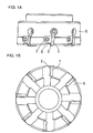
- Figs. 1A and 1B show a face milling tool, to which the present invention is applied.
- a plurality of throwaway tips prepared by brazing CBN sintered bodies 2 to only upper surfaces in the vicinity of single ends of bases 1 consisting of cemented carbide blocks are radially mounted on the outer periphery of a cutter body 5 as shown in Fig. 1B, with pressers 6 and clamp screws 7.
- Japanese Patent Laying-Open No. Japanese Patent Laying-Open No.
- a throwaway tip consisting of a CBN sintered body and a cutter for milling, which enables high-speed face milling of components consisting of gray cast iron with long life by optimizing the shapes of an insert, a minor insert, a negative land etc. of the throwaway tip.
- Cutting speeds V practically employed for face-milling cast iron with a cemented carbide or coated tool and a ceramics tool are about 150 to 250 m/min. and about 400 m/min. respectively.
- a CBN tool which is excellent in wear resistance and applicable to high-speed cutting, such as the throwaway tip for milling proposed in the aforementioned gazette, for example, is capable of working cast iron at a cutting speed V of 500 to 1500 m/min. under a dry condition.
- a cutting speed V practically employed for end-milling cast iron with a high-speed steel, cemented carbide or coated tool is about 30 to 100 m/min.
- a CBN tool is capable of working cast iron at a cutting speed V of 100 to 1500 m/min. under a dry condition.
- the CBN sintered body tool is capable of face-milling cast iron at the cutting speed V of 500 to 1500 m/min. under a dry condition. Under a wet condition, however, the CBN sintered body tool is employed at a practical cutting speed V within the range of 500 to 700 m/min. If the cutting speed V exceeds this range, the insert of the CBN sintered body tool is heat-cracked to remarkably reduce the tool life.
- the CBN sintered body tool is capable of end-milling cast iron at the cutting speed V of 100 to 1500 m/min. under a dry condition. Under a wet condition, however, the CBN sintered body tool is employed at a practical cutting speed V within the range of 100 to 300 m/min. If the cutting speed V exceeds this range, the insert is heat-cracked to remarkably reduce the tool life similarly to the case of face milling.
- the tool life is reduced under a wet condition since the heat conductivity of the conventional CBN sintered body is less than 400 W/m .
- the cutting speed V of the CBN sintered body tool is increased under a wet condition similarly to that under a dry condition, the tool life is unpreferably reduced to increase the working cost in both of face milling and end milling. Therefore, the CBN sintered body tool must cut workpieces which are remarkably deformed or distorted by heat generated in cutting or components to be protected against even the slightest deformation caused by heat generated in cutting under a dry condition or at a low cutting speed V causing no heat cracking under a wet condition.
- the working is performed under a condition identical to the wet condition is a pre-step includes wet working such as rough working or perforation due to a cutting fluid remaining on the working spots, and hence the insert of the tool is still heat-cracked and hence sufficient life cannot be obtained in this case.
- An object of the present invention is to provide a cutting tool for milling which can attain sufficient tool life particularly in high-speed face milling under a wet condition at a cutting speed V of at least 800 m/min. and in high-speed end milling under a wet condition at a cutting speed V of at least 300 m/min.
- the cutting tool for milling comprises an insert consisting of a cubic boron nitride sintered body having heat conductivity of at least 400 W/m . K at 120°C and a thermal expansion coefficient within the range of at least 3.0 x 10 -6 /K and not more than 4.0 x 10 -6 /K in the temperature range of 20°C to 600°C.
- the inventive sintered body tool having such a structure attains long life in high-speed milling under a wet condition for the following reason:
- the CBN sintered body forming its insert has heat conductivity of less than 400 W/m . K at 20°C and a thermal expansion coefficient exceeding 4.0 x 10 -6 /K in the range of 20°C to 600°C.
- the sintered body Under a dry condition, the sintered body can withstand thermal shock since its cutting edge is not rapidly quenched and hence temperature difference in a heat cycle is small.
- a remarkable temperature gradient is caused in the vicinity of the cutting edge and high tensile stress is applied to the insert in quenching due to large temperature difference in the heat cycle and high heat conductivity. Further, it is conceived that heat cracking is readily caused by repetition of remarkable expansion and contraction due to the high thermal expansion coefficient.
- the heat conductivity of the CBN sintered body forming the insert is at least 400 W/m ⁇ K and the thermal expansion coefficient is within the range of at least 3.0 x 10 -6 /K and not more than 4.0 x 10 -6 /K in the range of 20°C to 600°C, whereby heat generated when the insert comes into contact with workpieces in high-speed milling can efficiently escape to the overall sintered body.
- thermal expansion of the sintered body is small in the vicinity of the insert and the heat moves toward the overall sintered body as described above, whereby a temperature gradient caused between the insert and the interior of the sintered body is so small that tensile stress resulting from thermal expansion difference is reduced.
- the insert is subjected to small tensile stress when rapidly quenched with a cutting fluid in slipping, and thermal shock serving as the main factor for heat cracking can be reduced.
- the heat conductivity of the cubic boron nitride sintered body forming the insert is more preferably at least 600 W/m ⁇ K at 120°C.
- the cubic boron nitride content of the cubic boron nitride sintered body forming the insert is preferably at least 99 volume %. This is because the aforementioned thermophysical values can be attained by increasing the content of CBN, having the highest heat conductivity after that of diamond and a low thermal expansion coefficient, to at least 99 volume % for reliably attaining desired thermophysical properties.
- the mechanical strength can be improved by preparing the CBN sintered body from CBN grains of 0.01 to 1.0 ⁇ m in grain size and increasing contact areas of these CBN grains for ensuring the effect of suppressing chipping.
- the transverse rupture strength of the CBN sintered body forming the insert of the inventive cutting tool for milling is preferably at least 80 kgf/mm 2 , in consideration of chipping resistance against mechanical shock.
- the inventive cutting tool for milling is employed under a wet condition at a cutting speed V of at least 800 m/min., to be capable of attaining long life, which can be attained by the conventional CBN tool under a dry condition.
- the inventive cutting tool for milling is employed under a wet condition at a cutting speed V of at least 300 m/min., to be capable of attaining long life, which can be attained by the conventional CBN tool under a dry condition.
- the insert is prepared from the CBN sintered body having the heat conductivity and the thermal expansion coefficient within the prescribed ranges respectively, while the CBN grain size and the transverse rupture strength thereof are also in the prescribed ranges respectively.
- the inventive cutting tool for milling suppresses chipping resulting from heat cracking, can extend the tool life in wet face milling at the cutting speed V of at least 800 m/min. or at least 1000 m/min. and in wet end milling at the cutting speed V of at least 300 m/min. or at least 500 m/min., and can remarkably improve productivity in high-speed milling of components consisting of gray cast iron under a wet condition, in particular.
- Figs. 1A and 1B are a plan view and a front elevational view of a conventional face milling cutter employing throwaway tips.
- Cutting tool samples Nos. 1 to 10 were prepared with inserts of CBN sintered bodies having physical values shown in Table 1 respectively, and subjected to a milling test for plates (100 by 150 mm in section) of gray cast iron FC250 with face milling cutters.
- the samples Nos. 1 to 5 are inventive, and the samples Nos. 6 to 10 are comparative.
- Table 1 shows heat conductivity at 120°C, a thermal expansion coefficient in the temperature range of 20°C to 600°C, and transverse rupture strength in three-point bending measurement at a span of 4 mm.
- the milling test was performed under the following cutting conditions:
- each of the inventive cutting tool samples Nos. 1 to 5 exhibited heat conductivity of at least 400 W/m . K at 120°C and a thermal expansion coefficient within the range of at least 3.0 x 10 -6 /K to 4.0 x 10 -6 /K in the temperature range of 20°C to 600°C, and attained a high cuttable pass count under a wet cutting condition.
- the tool life of the sample No. 6 was remarkably reduced with a cuttable pass count of 25 under a wet cutting condition while that under a dry cutting condition was 170. This is conceivably because heat cracking was readily caused due to repetition of remarkable expansion and contraction under the wet cutting condition resulting from the thermal expansion coefficient exceeding 4.0 x 10 -6 /K in the temperature range of 20°C to 600°C, although the heat conductivity of the cutting tool sample No. 6 was in excess of 400 W/m ⁇ K at 120°C.
- the tool life of the comparative cutting tool sample No. 7 was extremely short under both dry and wet conditions, despite the high heat conductivity of 650 W/m ⁇ K at 120°C. This is conceivably because heat cracking was readily caused due to the thermal expansion coefficient exceeding 4.0 x 10 -6 /K in the temperature range of 20°C to 600°C and the mechanical strength was reduced due to the large CBN grain size exceeding 2.0 ⁇ m.
- the comparative cutting tool sample No. 8 which was capable of cutting workpieces 170 times under a dry cutting condition, was chipped in single cutting under a wet cutting condition, to exhibit extreme difference between the dry and wet conditions. This is conceivably because the heat conductivity of the sample No. 8 was extremely lower than 400 W/m ⁇ K, the thermal expansion coefficient was at a high level of 5.1 x 10 -6 /K in the temperature range of 20°C to 600°C, and the CBN content was at a low level of 70 volume %.
- the comparative cutting tool samples Nos. 9 and 10 also exhibited extreme difference between dry and wet conditions, to substantiate that the heat conductivity remarkably influences the tool life under a wet cutting condition.
- the cutting tool sample No. 1 exhibited slightly large difference in tool life between the dry and wet conditions. This is conceivably because the heat conductivity of the sample No. 1 was slightly lower as compared with the samples Nos. 2 to 5 due to the CBN content lower than 99 volume %. The tool life of the sample No. 2 was slightly shorter as compared with the remaining inventive samples, although the same hardly exhibited difference between the dry and wet conditions. This is conceivably because the transverse rupture strength of the sample No. 2 was slightly reduced due to the relatively large CBN grain size.
- Example 2 results substantially similar to those in Example 1 as a total tendency also in high-speed cutting at the cutting speed V of 1500 m/min., although the cuttable pass counts were different from those in Example 1. It is inferred that the influence by the transverse rupture strength remarkably reflected on the difference of the cuttable pass counts in Examples 1 and 2 due to the high-speed cutting condition in Example 2.
- End mills were formed with inserts prepared from the CBN sintered body samples employed in Example 1, and subjected to a lateral cutting test for plates (100 by 150 mm in section) of gray cast iron FC250 under the following cutting conditions:
Landscapes
- Engineering & Computer Science (AREA)
- Mechanical Engineering (AREA)
- Ceramic Products (AREA)
- Cutting Tools, Boring Holders, And Turrets (AREA)
- Milling Processes (AREA)
Applications Claiming Priority (3)
| Application Number | Priority Date | Filing Date | Title |
|---|---|---|---|
| JP8627397 | 1997-04-04 | ||
| JP9086273A JPH10277831A (ja) | 1997-04-04 | 1997-04-04 | フライス用切削工具 |
| JP86273/97 | 1997-04-04 |
Publications (3)
| Publication Number | Publication Date |
|---|---|
| EP0868957A2 true EP0868957A2 (fr) | 1998-10-07 |
| EP0868957A3 EP0868957A3 (fr) | 2002-04-24 |
| EP0868957B1 EP0868957B1 (fr) | 2003-10-08 |
Family
ID=13882227
Family Applications (1)
| Application Number | Title | Priority Date | Filing Date |
|---|---|---|---|
| EP98302480A Expired - Lifetime EP0868957B1 (fr) | 1997-04-04 | 1998-03-31 | Outil à fraiser |
Country Status (5)
| Country | Link |
|---|---|
| US (1) | US5890847A (fr) |
| EP (1) | EP0868957B1 (fr) |
| JP (1) | JPH10277831A (fr) |
| CA (1) | CA2233401C (fr) |
| DE (1) | DE69818735T2 (fr) |
Cited By (6)
| Publication number | Priority date | Publication date | Assignee | Title |
|---|---|---|---|---|
| WO2000020149A1 (fr) * | 1998-10-08 | 2000-04-13 | De Beers Industrial Diamonds (Proprietary) Limited | Element d'outil |
| FR2789613A1 (fr) * | 1999-02-17 | 2000-08-18 | Peugeot Citroen Automobiles Sa | Procede de surfacage d'un objet, notamment d'un bloc-cylindres, et fraise pour la mise en oeuvre de ce procede |
| EP1462199A1 (fr) * | 2003-03-22 | 2004-09-29 | Walter Ag | Plaquette de coupe et outil de fraisage |
| EP1279653A4 (fr) * | 2000-03-08 | 2006-06-28 | Sumitomo Electric Industries | Agglomere revetu de nitrure de bore cubique |
| WO2007097685A1 (fr) | 2006-02-22 | 2007-08-30 | Seco Tools Ab | Insert de fraisage de NITRURE DE BORE CUBIQUE (CBN) et outil D'insert de fraisage pour filetage À LA FRAISE |
| EP2497591A4 (fr) * | 2009-11-02 | 2017-02-08 | Sumitomo Electric Hardmetal Corp. | Procédé pour traiter de la fonte difficile à couper |
Families Citing this family (4)
| Publication number | Priority date | Publication date | Assignee | Title |
|---|---|---|---|---|
| JP2001129703A (ja) * | 1999-11-04 | 2001-05-15 | Sumitomo Electric Ind Ltd | 切削工具用被覆焼結体 |
| CA2571470C (fr) * | 2005-11-18 | 2013-02-05 | Sumitomo Electric Hardmetal Corp. | Corps fritte au cbn pour usinage a haute integrite de surface, outil de coupe avec corps fritte au cbn, et methode de coupe applicable |
| US8148282B2 (en) * | 2008-09-18 | 2012-04-03 | Diamond Innovations, Inc. | Method of solid PCBN sythesis |
| CN117583655B (zh) * | 2024-01-18 | 2024-03-29 | 常州市福尔特工具有限公司 | 一种用于大平面加工的高效铣削盘铣刀 |
Family Cites Families (10)
| Publication number | Priority date | Publication date | Assignee | Title |
|---|---|---|---|---|
| US3767371A (en) * | 1971-07-01 | 1973-10-23 | Gen Electric | Cubic boron nitride/sintered carbide abrasive bodies |
| JPS5138300A (ja) * | 1974-09-30 | 1976-03-30 | Hitachi Ltd | Ritsuboshochitsukahosono seizohoho |
| US5332629A (en) * | 1985-01-11 | 1994-07-26 | Sumitomo Electric Industries, Ltd. | Boron nitride system including an hBN starting material with a catalyst and a sintered cNB body having a high heat conductivity based on the catalyst |
| JPS61201751A (ja) * | 1985-03-04 | 1986-09-06 | Nippon Oil & Fats Co Ltd | 高硬度焼結体およびその製造方法 |
| JP3035797B2 (ja) * | 1991-07-04 | 2000-04-24 | 三菱マテリアル株式会社 | 高強度を有する立方晶窒化ほう素基超高圧焼結材料製切削チップ |
| JP3146747B2 (ja) * | 1993-04-01 | 2001-03-19 | 三菱マテリアル株式会社 | 耐摩耗性および耐欠損性のすぐれた立方晶窒化ほう素基超高圧焼結材料製切削工具 |
| DE69427722T2 (de) * | 1993-05-21 | 2002-05-08 | Kabushiki Kaisha Toshiba, Kawasaki | Sinterkörper aus Aluminiumnitriol und Verfahren zu seiner Herstellung |
| JPH0885012A (ja) * | 1994-07-06 | 1996-04-02 | Sumitomo Electric Ind Ltd | 回転切削工具、同工具用超高圧焼結体ねじれチップ及びその工具、チップの製造方法 |
| JP2751873B2 (ja) * | 1994-09-22 | 1998-05-18 | 住友電気工業株式会社 | フライス用スローアウェイチップおよびそれを用いたフライス用カッタ |
| JPH08206902A (ja) * | 1994-12-01 | 1996-08-13 | Sumitomo Electric Ind Ltd | 切削用焼結体チップおよびその製造方法 |
-
1997
- 1997-04-04 JP JP9086273A patent/JPH10277831A/ja active Pending
-
1998
- 1998-03-26 CA CA002233401A patent/CA2233401C/fr not_active Expired - Lifetime
- 1998-03-30 US US09/050,597 patent/US5890847A/en not_active Expired - Lifetime
- 1998-03-31 EP EP98302480A patent/EP0868957B1/fr not_active Expired - Lifetime
- 1998-03-31 DE DE69818735T patent/DE69818735T2/de not_active Expired - Lifetime
Cited By (10)
| Publication number | Priority date | Publication date | Assignee | Title |
|---|---|---|---|---|
| WO2000020149A1 (fr) * | 1998-10-08 | 2000-04-13 | De Beers Industrial Diamonds (Proprietary) Limited | Element d'outil |
| US6579045B1 (en) | 1998-10-08 | 2003-06-17 | Robert Fries | Tool component |
| FR2789613A1 (fr) * | 1999-02-17 | 2000-08-18 | Peugeot Citroen Automobiles Sa | Procede de surfacage d'un objet, notamment d'un bloc-cylindres, et fraise pour la mise en oeuvre de ce procede |
| EP1279653A4 (fr) * | 2000-03-08 | 2006-06-28 | Sumitomo Electric Industries | Agglomere revetu de nitrure de bore cubique |
| EP1462199A1 (fr) * | 2003-03-22 | 2004-09-29 | Walter Ag | Plaquette de coupe et outil de fraisage |
| US6921233B2 (en) | 2003-03-22 | 2005-07-26 | Walter Ag | Cutter insert and milling tool |
| KR100736065B1 (ko) | 2003-03-22 | 2007-07-06 | 발터 아게 | 커터 인서트 및 밀링 공구 |
| WO2007097685A1 (fr) | 2006-02-22 | 2007-08-30 | Seco Tools Ab | Insert de fraisage de NITRURE DE BORE CUBIQUE (CBN) et outil D'insert de fraisage pour filetage À LA FRAISE |
| EP1989016A4 (fr) * | 2006-02-22 | 2009-12-09 | Seco Tools Ab Publ | Insert de fraisage de nitrure de bore cubique (cbn) et outil d`insert de fraisage pour filetage à la fraise |
| EP2497591A4 (fr) * | 2009-11-02 | 2017-02-08 | Sumitomo Electric Hardmetal Corp. | Procédé pour traiter de la fonte difficile à couper |
Also Published As
| Publication number | Publication date |
|---|---|
| EP0868957B1 (fr) | 2003-10-08 |
| US5890847A (en) | 1999-04-06 |
| CA2233401A1 (fr) | 1998-10-04 |
| JPH10277831A (ja) | 1998-10-20 |
| CA2233401C (fr) | 2002-02-12 |
| DE69818735D1 (de) | 2003-11-13 |
| DE69818735T2 (de) | 2004-08-12 |
| EP0868957A3 (fr) | 2002-04-24 |
Similar Documents
| Publication | Publication Date | Title |
|---|---|---|
| US5707185A (en) | Indexable insert for milling and milling cutter employing the same | |
| Richards et al. | Use of ceramic tools for machining nickel based alloys | |
| EP1125667B1 (fr) | Fraise sphérique à queue | |
| JP4728256B2 (ja) | 高品位高能率加工用切削工具およびそれを用いた切削加工方法 | |
| Liu et al. | Wear patterns and mechanisms of cutting tools in high-speed face milling | |
| Narutaki et al. | High-speed machining of Inconel 718 with ceramic tools | |
| EP1320435B1 (fr) | Outil a resistance accrue au deplacement et procede de sa fabrication | |
| EP0194811B1 (fr) | Outils de coupe en matériau céramique renforcé | |
| US8496415B2 (en) | Negative insert having double-positive clearance surface | |
| EP0868957B1 (fr) | Outil à fraiser | |
| AU2001295076A1 (en) | Tool with improved resistance to displacement | |
| Xu et al. | Cutting performance of tools made of different materials in the machining of 42CrMo4 high-strength steel: a comparative study | |
| Braghini Jr et al. | An investigation of the wear mechanisms of polycrystalline cubic boron nitride (PCBN) tools when end milling hardened steels at low/medium cutting speeds | |
| US5066170A (en) | Tool bit | |
| Chryssolouris | Turning of hardened steels using CBN tools | |
| Mehrotra | Applications of ceramic cutting tools | |
| JPH1036174A (ja) | 焼結セラミック材料、その材料の焼結方法及び高速機械加工方法 | |
| Zimmerman et al. | Machinability test methods | |
| JPH08192305A (ja) | スローアウェイチップおよびその製造方法 | |
| Heath | Ultrahard tool materials | |
| JP2505803B2 (ja) | エンドミル | |
| Oishi et al. | Study on the fracture characteristics of ceramic cutting tools (first report) | |
| JPS6076902A (ja) | 高硬度材料切削用工具 | |
| OKUsHIMA et al. | On the Applications of Ceramics in Machining | |
| JPS6360253A (ja) | 温、熱間鍛造用工具 |
Legal Events
| Date | Code | Title | Description |
|---|---|---|---|
| PUAI | Public reference made under article 153(3) epc to a published international application that has entered the european phase |
Free format text: ORIGINAL CODE: 0009012 |
|
| AK | Designated contracting states |
Kind code of ref document: A2 Designated state(s): AT BE CH DE DK ES FI FR GB GR IE IT LI LU MC NL PT SE Kind code of ref document: A2 Designated state(s): DE FR GB IT SE |
|
| PUAL | Search report despatched |
Free format text: ORIGINAL CODE: 0009013 |
|
| AK | Designated contracting states |
Kind code of ref document: A3 Designated state(s): AT BE CH DE DK ES FI FR GB GR IE IT LI LU MC NL PT SE |
|
| AX | Request for extension of the european patent |
Free format text: AL;LT;LV;MK;RO;SI |
|
| 17P | Request for examination filed |
Effective date: 20020502 |
|
| 17Q | First examination report despatched |
Effective date: 20020719 |
|
| AKX | Designation fees paid |
Free format text: DE FR GB IT SE |
|
| GRAH | Despatch of communication of intention to grant a patent |
Free format text: ORIGINAL CODE: EPIDOS IGRA |
|
| GRAS | Grant fee paid |
Free format text: ORIGINAL CODE: EPIDOSNIGR3 |
|
| GRAA | (expected) grant |
Free format text: ORIGINAL CODE: 0009210 |
|
| AK | Designated contracting states |
Kind code of ref document: B1 Designated state(s): DE FR GB IT SE |
|
| REG | Reference to a national code |
Ref country code: GB Ref legal event code: FG4D |
|
| REG | Reference to a national code |
Ref country code: IE Ref legal event code: FG4D |
|
| REF | Corresponds to: |
Ref document number: 69818735 Country of ref document: DE Date of ref document: 20031113 Kind code of ref document: P |
|
| REG | Reference to a national code |
Ref country code: SE Ref legal event code: TRGR |
|
| PG25 | Lapsed in a contracting state [announced via postgrant information from national office to epo] |
Ref country code: GB Free format text: LAPSE BECAUSE OF NON-PAYMENT OF DUE FEES Effective date: 20040331 |
|
| ET | Fr: translation filed | ||
| PLBE | No opposition filed within time limit |
Free format text: ORIGINAL CODE: 0009261 |
|
| STAA | Information on the status of an ep patent application or granted ep patent |
Free format text: STATUS: NO OPPOSITION FILED WITHIN TIME LIMIT |
|
| 26N | No opposition filed |
Effective date: 20040709 |
|
| GBPC | Gb: european patent ceased through non-payment of renewal fee | ||
| REG | Reference to a national code |
Ref country code: IE Ref legal event code: MM4A |
|
| REG | Reference to a national code |
Ref country code: FR Ref legal event code: PLFP Year of fee payment: 19 |
|
| REG | Reference to a national code |
Ref country code: FR Ref legal event code: PLFP Year of fee payment: 20 |
|
| PGFP | Annual fee paid to national office [announced via postgrant information from national office to epo] |
Ref country code: FR Payment date: 20170213 Year of fee payment: 20 Ref country code: SE Payment date: 20170313 Year of fee payment: 20 |
|
| PGFP | Annual fee paid to national office [announced via postgrant information from national office to epo] |
Ref country code: IT Payment date: 20170320 Year of fee payment: 20 |
|
| PGFP | Annual fee paid to national office [announced via postgrant information from national office to epo] |
Ref country code: DE Payment date: 20170329 Year of fee payment: 20 |
|
| REG | Reference to a national code |
Ref country code: DE Ref legal event code: R071 Ref document number: 69818735 Country of ref document: DE |
|
| REG | Reference to a national code |
Ref country code: SE Ref legal event code: EUG |