EP0868958A1 - Verfahren zum kontinuierlichen Herstellen eines mit Lötwerkstoff hergestellten metallischen Bands, dafür hergestelltes Band und in diesem Band zugeschnittenes Kontaktwerkstück - Google Patents
Verfahren zum kontinuierlichen Herstellen eines mit Lötwerkstoff hergestellten metallischen Bands, dafür hergestelltes Band und in diesem Band zugeschnittenes Kontaktwerkstück Download PDFInfo
- Publication number
- EP0868958A1 EP0868958A1 EP98400792A EP98400792A EP0868958A1 EP 0868958 A1 EP0868958 A1 EP 0868958A1 EP 98400792 A EP98400792 A EP 98400792A EP 98400792 A EP98400792 A EP 98400792A EP 0868958 A1 EP0868958 A1 EP 0868958A1
- Authority
- EP
- European Patent Office
- Prior art keywords
- solder
- strip
- groove
- nozzle
- metal
- Prior art date
- Legal status (The legal status is an assumption and is not a legal conclusion. Google has not performed a legal analysis and makes no representation as to the accuracy of the status listed.)
- Withdrawn
Links
Images

Classifications
-
- B—PERFORMING OPERATIONS; TRANSPORTING
- B23—MACHINE TOOLS; METAL-WORKING NOT OTHERWISE PROVIDED FOR
- B23K—SOLDERING OR UNSOLDERING; WELDING; CLADDING OR PLATING BY SOLDERING OR WELDING; CUTTING BY APPLYING HEAT LOCALLY, e.g. FLAME CUTTING; WORKING BY LASER BEAM
- B23K3/00—Tools, devices or special appurtenances for soldering, e.g. brazing, or unsoldering, not specially adapted for particular methods
- B23K3/06—Solder feeding devices; Solder melting pans
- B23K3/0607—Solder feeding devices
- B23K3/063—Solder feeding devices for wire feeding
-
- B—PERFORMING OPERATIONS; TRANSPORTING
- B23—MACHINE TOOLS; METAL-WORKING NOT OTHERWISE PROVIDED FOR
- B23K—SOLDERING OR UNSOLDERING; WELDING; CLADDING OR PLATING BY SOLDERING OR WELDING; CUTTING BY APPLYING HEAT LOCALLY, e.g. FLAME CUTTING; WORKING BY LASER BEAM
- B23K2101/00—Articles made by soldering, welding or cutting
- B23K2101/36—Electric or electronic devices
- B23K2101/38—Conductors
Definitions
- the invention relates to a continuous production method for a strip metal with incorporated solder, in particular for constituting parts of contact, the strip obtained by this process and a contact piece obtained by cutting this strip.
- Contact parts are advantageously cut from a strip metallic.
- parts of contact are provided with a solder in the area of the electrical contact.
- a solder for constitute metal bands with incorporated brazing, it has been proposed to overlap a metal strip and a solder strip, and proceed to cold co-lamination. This method introduced into the resulting strip mechanical stresses that are released when cutting the strip in contact pieces. This may result in deformation of the part contact, or orientation or detachment of the solder, which affect the automated operation of a manufacturing line.
- One of the aims of the invention is to propose a method for producing a metal band with incorporated solder, which ensures a good bond between the solder and the metal strip, as well as good stability of the parts cut contact, in particular in their use in the technique of surface mounted components (CMS).
- CMS surface mounted components
- Another object of the invention is to propose such a process, which is economically satisfactory, i.e. which ensures a high speed of realization, while allowing to have an extra thickness of solder at above the groove of the metal strip.
- Yet another object of the invention is to propose a process which allows calibrate and regulate the solder deposit on the strip, in particular by as a function of the temperature of the strip and of the solder, the speed of scrolling of the strip and the output flow of the solder.
- the subject of the invention is also a brazed metal strip incorporated obtained by the above process.
- the invention also covers the contact parts obtained by cutting. a metal strip with incorporated brazing obtained by the above method.
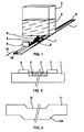
- a metal strip 1 is provided with a groove longitudinal 2.
- the groove 2 is obtained by milling or by removal a continuous chip, for example.
- Band 1 is advantageously unwound from a reel 13 and wound on another reel 14 (see Figures 4 and 7). Between the two coils, it moves longitudinally, on a substantially straight course, remaining substantially horizontal, the groove 2 being arranged on top, so as to be able to receive a deposit of solder 3.
- This liquid solder is likely to be deposited, for example by gravity, via a nozzle 6, in the groove 2 of the strip 1 which passes under the nozzle 6.
- two guides 7 and 8 for example made of stainless steel, to ensure the confinement of the liquid solder in the groove 2, and avoid overflows while allowing additional solder thickness.
- the two guides 7 and 8 are long enough to allow the solder 3 to have a stable shape at the outlet of the guides. Downstream of guides 7 and 8, a scraper knife 9 is arranged to ensure a constant thickness at the brazing 3. Downstream of the scraper 9, the strip 1, which moves in the direction of the arrow 10, is presented with its groove 2 filled with solder 3a of constant thickness, this thickness being slightly greater than the groove depth 2.
- Figure 2 is a cross-sectional view to the right of the outlet of the guides 7 and 8 of FIG. 1.
- the groove 2 is formed by removing metal continuously on the upper part of the strip 1.
- Guides 7 and 8 are placed on the side and other of the groove 2.
- the solder 3 has a thickness slightly greater than the depth of groove 2.
- the width of the groove 2 is 4mm
- the thickness of the strip 1 is 0.25mm
- the depth of the groove 2 is 0.10mm
- the excess thickness of the solder 3 is between 0 and about 0.02mm.
- Guides 7 and 8 are for example spaced from strip 1 a clearance of the order of 0.01mm.
- the groove 12 is not obtained by removing metal in continuous, but by deformation of the strip 11, by cold profiling by example.
- the strip 11 has on its face opposite the groove of frustoconical section 12 a complementary protuberance 12a.
- the strip 1, 11 is preferably made of hot-tinned copper alloy, that is to say whose surface, covered with a few micrometers of tin, is clean.
- the reservoir 4 of liquid solder 5 is under an inert atmosphere, for example under nitrogen, and under regulated pressure, so as to control the nozzle flow rate outlet 6.
- the reservoir 4 is preferably closed in an inert atmosphere to avoid oxidation of the tin.
- the exit of the solder by the nozzle 6 is at a regulated flow.
- the output flow of the solder and the running speed of the strip 1 under the nozzle 6 can be controlled.
- the solder can consist of pure tin or different types of alloys brazing, corresponding to different temperature ranges from reflow.
- the liquid solder deposit by the nozzle 6 is carried out under an atmosphere inert, i.e. for example in an enclosure under nitrogen 15 (see figure 7). Upstream and downstream of this enclosure 15, the strip 1 is driven by sets of rollers 16 and 17 respectively.
- These sets of rollers 16 and 17 are preferably supplied with current electric by a low voltage generator, so as to ensure a heating of the strip between the sets of rollers, for example by effect Joule.
- the regulation of the strip temperature 1.11 is ensured by example using an infrared radiation detector or a pyrometric probe in the vicinity of nozzle 6.
- the setting range of the temperature is for example between 0 and 180 ° C. It is indeed necessary to control the temperature difference between the 1.11 strip of a part and the liquid solder deposited by the nozzle 6 on the other hand.
- the solder 3 must no longer be liquid but solid.
- the speed of movement of the strip 1.11 under the nozzle 6 is regulated by such that the solder 3 has an excess thickness relative to the groove depth 2.12. This extra thickness is limited by the scraper 9.
- the implementation of the method according to the invention allows the realization of a brazing band incorporated with a speed of the order of 10m / min.
- the embodiment described and shown has a single groove on the metal strip, corresponding to a single solder deposit, but the metal strip may have several grooves capable of receiving solder.
- the solder deposits can be simultaneous or offset.
- the Solder deposits are made successively.
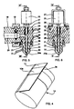
- the head of the extruder 18 is connected by a connection flange 19 to a nozzle 20.
- This nozzle 20 has at its lower end a nozzle tip 20a which is fixed so removable by clamping screws 21 to the nozzle body 20.
- the nozzle tip 20a is interchangeable and has an internal passage 22 with a suitable profile depending on the applications envisaged.
- This internal passage 22 communicates with an elbow passage 23 inside the nozzle body 20, which bent passage 23 in turn communicates with the internal passage 24 of the extruder head 18.
- the nozzle body 20 supports an electromagnet 25 or a jack (not shown) which actuates a shutter in the shape of a needle pin 26, for authorize or stop the flow of tin flowing through the nozzle tip 20a.
- This needle rod 26 crosses the bent passage 23 and the internal passage 22 end piece 20a.
- the electromagnet 25 is retained on the nozzle body 20 by via a U-shaped bracket 27.
- the extruder has several regulated heating zones, so that get at the head of the liquid tin extruder by starting at level of an entry hopper with tin pellets, which avoids any oxidation of liquid tin.
- the nozzle body 20 comprises four heating cartridges 28 which surround the bent passage 23 of the nozzle body 20 to allow the tin temperature regulation at the nozzle.
- Drivers 29 are connected to the cartridges 28 for their supply electric.
- a heating collar 30 is fitted onto the nozzle 20a and connected to electrical connections 31 to regulate the temperature at the nozzle tip 20a.
- the nozzle is oriented in one direction substantially perpendicular to the barrel of the extruder. So the filing tin can be regulated according to the speed of the web, the temperature of the tin and the temperature of the strip. The extruder is subject to these parameters.
- Each of the coils 13 and 14 is carried by a respective pallet 33,34.
- Pallets 33 and 34 serve respectively as unwinder and as reel winder.
- the metal strip 11 first passes through a forming block 35 with removable rollers, then by a straightening block 36 also with removable rollers, then it passes through a module cleaning 37 with pressurized hot water, followed by a drying module 38, conventionally in the art.
- a accumulator 39 Downstream of the first set of drive rollers 16 is provided a accumulator 39 to allow the tape to return in the event of finding of a defect, as explained below.
- the accumulator 39 there is the aforementioned enclosure 15 which contains the extruder 18 under a inert atmosphere, as well as a spray flux pump 40.
- the strip 11 on which the liquid tin has been deposited passes through a water cooling module 41 before the excess allowance tin is machined by the scraper 9. At the scraper 9, the excess tin is recovered for recycling.
- the two accumulators 39 and 44 which allow the part to be rolled back defective tape to the right of the extruder nozzle 18 to selectively deposit tin in defective areas, without affecting the operation of the reels of the coils 13 and 14. Then, the process resumes normal course by advancing the tape to its position former.
- the accumulators 39 and 44 include displaceable rollers with bevel gear.
- Coaches 16 and 17 can be as a variant of the endless belt type.
- the invention is not limited to the deposit of tin, but can also apply to any material deposited in the liquid phase on the bandaged.
Landscapes
- Engineering & Computer Science (AREA)
- Mechanical Engineering (AREA)
- Coating With Molten Metal (AREA)
- Molten Solder (AREA)
Applications Claiming Priority (2)
| Application Number | Priority Date | Filing Date | Title |
|---|---|---|---|
| FR9704124A FR2761627B1 (fr) | 1997-04-04 | 1997-04-04 | Procede de realisation d'une bande metallique a brasure incorporee, pour constituer des pieces de contact |
| FR9704124 | 1997-04-04 |
Publications (1)
| Publication Number | Publication Date |
|---|---|
| EP0868958A1 true EP0868958A1 (de) | 1998-10-07 |
Family
ID=9505524
Family Applications (1)
| Application Number | Title | Priority Date | Filing Date |
|---|---|---|---|
| EP98400792A Withdrawn EP0868958A1 (de) | 1997-04-04 | 1998-04-03 | Verfahren zum kontinuierlichen Herstellen eines mit Lötwerkstoff hergestellten metallischen Bands, dafür hergestelltes Band und in diesem Band zugeschnittenes Kontaktwerkstück |
Country Status (2)
| Country | Link |
|---|---|
| EP (1) | EP0868958A1 (de) |
| FR (1) | FR2761627B1 (de) |
Cited By (3)
| Publication number | Priority date | Publication date | Assignee | Title |
|---|---|---|---|---|
| WO2005118196A1 (de) * | 2004-06-01 | 2005-12-15 | Soutec Soudronic Ag | Verfahren und vorrichtung zum hartlöten |
| EP1797985A1 (de) * | 2005-12-19 | 2007-06-20 | Siemens Aktiengesellschaft | Schweissverfahren und Schweissvorrichtung |
| EP2025442A1 (de) * | 2007-08-13 | 2009-02-18 | Behr GmbH & Co. KG | Verfahren zum Beloten eines Werkstückes durch einen Flüssigkeitsvorhang ; Vorrichtung zur Durchführung des Verfahrens mit einem Giesshälter ; Werkstück belotet nach diesem Verfahren |
Citations (3)
| Publication number | Priority date | Publication date | Assignee | Title |
|---|---|---|---|---|
| DE1427343A1 (de) * | 1961-09-12 | 1969-04-24 | Siegfried Witte | Loetverfahren mit Metall auf Glas und seine Anwendung auf die Fertigung von Mehrscheibenisolierglas |
| WO1992016330A1 (en) * | 1991-03-13 | 1992-10-01 | Sigmund Ege | Apparatus and method for butt-splicing metal tapes |
| EP0598182A1 (de) * | 1992-11-19 | 1994-05-25 | Asymptotic Technologies, Inc. | Verfahren und Vorrichtung zum schnellen Abgeben von geringen Mengen von viskosen Materialien |
-
1997
- 1997-04-04 FR FR9704124A patent/FR2761627B1/fr not_active Expired - Fee Related
-
1998
- 1998-04-03 EP EP98400792A patent/EP0868958A1/de not_active Withdrawn
Patent Citations (3)
| Publication number | Priority date | Publication date | Assignee | Title |
|---|---|---|---|---|
| DE1427343A1 (de) * | 1961-09-12 | 1969-04-24 | Siegfried Witte | Loetverfahren mit Metall auf Glas und seine Anwendung auf die Fertigung von Mehrscheibenisolierglas |
| WO1992016330A1 (en) * | 1991-03-13 | 1992-10-01 | Sigmund Ege | Apparatus and method for butt-splicing metal tapes |
| EP0598182A1 (de) * | 1992-11-19 | 1994-05-25 | Asymptotic Technologies, Inc. | Verfahren und Vorrichtung zum schnellen Abgeben von geringen Mengen von viskosen Materialien |
Cited By (3)
| Publication number | Priority date | Publication date | Assignee | Title |
|---|---|---|---|---|
| WO2005118196A1 (de) * | 2004-06-01 | 2005-12-15 | Soutec Soudronic Ag | Verfahren und vorrichtung zum hartlöten |
| EP1797985A1 (de) * | 2005-12-19 | 2007-06-20 | Siemens Aktiengesellschaft | Schweissverfahren und Schweissvorrichtung |
| EP2025442A1 (de) * | 2007-08-13 | 2009-02-18 | Behr GmbH & Co. KG | Verfahren zum Beloten eines Werkstückes durch einen Flüssigkeitsvorhang ; Vorrichtung zur Durchführung des Verfahrens mit einem Giesshälter ; Werkstück belotet nach diesem Verfahren |
Also Published As
| Publication number | Publication date |
|---|---|
| FR2761627B1 (fr) | 1999-07-09 |
| FR2761627A1 (fr) | 1998-10-09 |
Similar Documents
| Publication | Publication Date | Title |
|---|---|---|
| EP0064891B1 (de) | Schweissanordnungen mit elektrischen Entladungen, insbesondere zum Lichtbogenschweissen | |
| EP0023472B1 (de) | Verfahren zum kontinuierlichen, wenigstens teilweisen Beschichten wenigstens einer Seite eines metallischen Substrats und Vorrichtung zur Durchführung des Verfahrens | |
| EP1630262B1 (de) | Verfahren zum Wiederaufbauen eines Bauteiles aus einkristallinem oder gerichtet erstarrtem Metall | |
| EP0002986B1 (de) | Verfahren und Vorrichtung zum Schweissen von geschützten Metallstücken | |
| FR2685235A1 (fr) | Electrode de soudage a resistance par points; extremite de contact pour une telle electrode; machine pour l'echange de ces extremites. | |
| FR2558085A1 (fr) | Procede et dispositif pour l'elaboration de rubans metalliques et semi-metalliques de faible epaisseur | |
| EP0217685B1 (de) | Verstärkte Platte, deren Herstellungsverfahren und Apparat zur Ausführung dieses Verfahrens | |
| WO2010106263A1 (fr) | Dispositif de soudobrasage | |
| FR3116454A1 (fr) | Procédé de fabrication additive ou de rechargement de pièces métalliques par amenée de fil | |
| FR2745208A1 (fr) | Procede de fabrication d'un fil stratifie de petit diametre et en particulier d'un fil electrode pour usinage par electroerosion et fil electrode obtenu | |
| FR2469967A1 (fr) | Procede de fabrication en continu, a partir d'un materiau fondu, d'un fil metallique de tres petit diametre, y compris dans l'etat vitreux, et dispositif pour executer ledit procede | |
| EP2612725B1 (de) | VERFAHREN UND VORRICHTUNG ZUR HERSTELLUNG EINER FÜLLDRAHTELEKTRODE MIT MECHANISCHEM SCHUTZ DES SCHWEIßPULVERS | |
| EP0041893B1 (de) | Schweissmaschine, insbesondere für Blechmäntel von Konservenbüchsen | |
| BE1018063A6 (fr) | Automate de soudure et procede de soudure. | |
| FR2761627A1 (fr) | Procede de realisation d'une bande metallique a brasure incorporee, pour constituer des pieces de contact | |
| EP0370934B1 (de) | Verfahren und Einrichtung zum Versorgen einer Kokille mit geschmolzenem Metall in einer Stranggiesseinrichtung für dünne Vorblöcke | |
| FR3103122A1 (fr) | Installation pour procede de fabrication additive d’une piece de turbomachine | |
| FR2502138A1 (fr) | Procede et dispositif d'application d'une couche de soudure sur les parties marginales metallisees d'une feuille vitreuse | |
| BE1000490A4 (fr) | Procede de coulee continue d'un ruban metallique. | |
| EP1106298A1 (de) | Verfahren und Vorrichtung zum Laserschweissen mit verringertem Energieverbrauch | |
| EP0828864A1 (de) | Verfahren und vorrichtung zum beschichtung eines metallischen bandes mit einem metal oder einer legierung mit niedrigen schmelzpunkt oder liquidespunkt wie das material aus dem das band besteht | |
| FR2559692A1 (fr) | Methode de preparation de demi-produits metalliques stratifies, notamment en acier, et dispositif de mise en oeuvre | |
| FR2548569A1 (fr) | Procede pour revetir une surface metallique par un metal d'apport par arc electrique et appareil pour la mise en oeuvre de ce procede | |
| FR3105747A1 (fr) | Procédé et installation de fabrication additive de pièce métallique | |
| BE436011A (de) |
Legal Events
| Date | Code | Title | Description |
|---|---|---|---|
| PUAI | Public reference made under article 153(3) epc to a published international application that has entered the european phase |
Free format text: ORIGINAL CODE: 0009012 |
|
| AK | Designated contracting states |
Kind code of ref document: A1 Designated state(s): DE FR GB IT |
|
| 17P | Request for examination filed |
Effective date: 19990322 |
|
| AKX | Designation fees paid |
Free format text: DE FR GB IT |
|
| STAA | Information on the status of an ep patent application or granted ep patent |
Free format text: STATUS: THE APPLICATION IS DEEMED TO BE WITHDRAWN |
|
| 18D | Application deemed to be withdrawn |
Effective date: 20011101 |