EP0869638A2 - Vorrichtung zum fernbedienten Zurücksetzen von Rechenanlagen, insbesondere Mikrocomputern - Google Patents
Vorrichtung zum fernbedienten Zurücksetzen von Rechenanlagen, insbesondere Mikrocomputern Download PDFInfo
- Publication number
- EP0869638A2 EP0869638A2 EP98103785A EP98103785A EP0869638A2 EP 0869638 A2 EP0869638 A2 EP 0869638A2 EP 98103785 A EP98103785 A EP 98103785A EP 98103785 A EP98103785 A EP 98103785A EP 0869638 A2 EP0869638 A2 EP 0869638A2
- Authority
- EP
- European Patent Office
- Prior art keywords
- reset
- control
- central unit
- control card
- unit
- Prior art date
- Legal status (The legal status is an assumption and is not a legal conclusion. Google has not performed a legal analysis and makes no representation as to the accuracy of the status listed.)
- Granted
Links
Images

Classifications
-
- G—PHYSICS
- G06—COMPUTING OR CALCULATING; COUNTING
- G06F—ELECTRIC DIGITAL DATA PROCESSING
- G06F1/00—Details not covered by groups G06F3/00 - G06F13/00 and G06F21/00
- G06F1/24—Resetting means
-
- H—ELECTRICITY
- H04—ELECTRIC COMMUNICATION TECHNIQUE
- H04L—TRANSMISSION OF DIGITAL INFORMATION, e.g. TELEGRAPHIC COMMUNICATION
- H04L12/00—Data switching networks
- H04L12/02—Details
- H04L12/12—Arrangements for remote connection or disconnection of substations or of equipment thereof
-
- H—ELECTRICITY
- H04—ELECTRIC COMMUNICATION TECHNIQUE
- H04M—TELEPHONIC COMMUNICATION
- H04M11/00—Telephonic communication systems specially adapted for combination with other electrical systems
- H04M11/007—Telephonic communication systems specially adapted for combination with other electrical systems with remote control systems
-
- Y—GENERAL TAGGING OF NEW TECHNOLOGICAL DEVELOPMENTS; GENERAL TAGGING OF CROSS-SECTIONAL TECHNOLOGIES SPANNING OVER SEVERAL SECTIONS OF THE IPC; TECHNICAL SUBJECTS COVERED BY FORMER USPC CROSS-REFERENCE ART COLLECTIONS [XRACs] AND DIGESTS
- Y02—TECHNOLOGIES OR APPLICATIONS FOR MITIGATION OR ADAPTATION AGAINST CLIMATE CHANGE
- Y02D—CLIMATE CHANGE MITIGATION TECHNOLOGIES IN INFORMATION AND COMMUNICATION TECHNOLOGIES [ICT], I.E. INFORMATION AND COMMUNICATION TECHNOLOGIES AIMING AT THE REDUCTION OF THEIR OWN ENERGY USE
- Y02D30/00—Reducing energy consumption in communication networks
- Y02D30/50—Reducing energy consumption in communication networks in wire-line communication networks, e.g. low power modes or reduced link rate
Definitions
- the control card is sent to the telephone network via an input element connected, a network access control with query of a Access codes are provided. It can reset everyone any other telephone connection can be operated remotely and saves time be carried out without any use at the location of the computer system necessary is.
- a network access device e.g. a network access device (NAD) must be connected.
- NAD network access device
- the function of the NAD can also be integrated in the control card itself be, e.g. in the input element or in the central unit.
- a Network access device (NAD) enables the controlled, secured Remote access via the telephone network to devices connected to the NAD, e.g. Microcomputer, through a password or code number query.
- the input element has means for protecting the electronic Circuit before overvoltage, which is a galvanic isolation of the circuit from the telephone network.
- the control card Circuit reset module on that with the input element and Central unit is connected.
- the circuit reset module has the task the device according to the invention in a defined initial state set. This can e.g. become necessary if after current fluctuations or Power failures the supply voltage of the electronic circuit was not set up correctly, or if a caller sent one to the Circuit wants to withdraw submitted input.
- the Establishing the connection to the caller with an acknowledgment tone or Acknowledgment tone sequence or also communicated by an acknowledgment data word in the If the device is controlled with DTMF signals, this signal will generated by the device via a tone generator. With control with The acknowledgment signals are sent from the central unit to data words.
- the caller can receive instructions in Send the form of DTMF signals or data words to the device.
- the electronic circuit After a successful plausibility check, the electronic circuit acknowledges the process with an acknowledgment tone generated by the tone generator or an acknowledgment tone sequence and resets the corresponding connected microcomputers via the expander unit and the associated reset elements. Invalid entries, such as line and output numbers that do not exist on the expander element, or invalid instructions are acknowledged with an error tone or an error tone sequence.
- Fig. 1 shows a device for remote reset of Microcomputers consisting of a control card and a plurality of Reset elements 6 assigned to microcomputers exists and via a Connection line 10 is connected to a telephone network 9.
- Control card and telephone network 9 can also include other elements 8, e.g. a Network access device (NAD), which have access to it Elements connected devices, in this case the invention Device, control over the telephone network 9 or other tasks fulfill.
- NAD Network access device
- the network access device 8 known type protects connected Devices from unwanted or unauthorized access by a password or Code number query. Only after correct identification of a caller, the NAD 8 establishes a connection to the control card.
- connection with the caller can also be made directly from the input element getting produced. Protection against unwanted or unjustified Access can then be done through a password or code number request in one Central unit 3 or in the input element 1 of the control card which must have NAD functions.
- the DTMF decoder 1.2 determines from the signal line 1.5 incoming frequency mix, whether a DTMF signal was sent, and then converts it to a binary code. As long as a valid DTMF signal is present on the signal line 1.5, is on a control output 1.4 of the DTMF decoder 1.2 to a control signal. Silence that Frequency mix or there are invalid frequencies on the DTMF decoder 1.2 , there is no control signal at the control output of the DTMF decoder 1.2.
- the DTMF decoder 1.2 thus also serves as a filter that detects external signals, e.g. Speech or FAX signals suppressed.
- the circuit reset module 2 is used to the electronic circuit Reset demand to a defined initial state. This happens on when the supply voltage of the electronic circuit, e.g. incorrect after a power failure or voltage fluctuations was set up, or if a caller has already submitted an entry wants to take back.
- the central unit 3 consists of the processor 3.1 and a memory unit 3.2 with program.
- the storage unit 3.2 for the program is preferably as a non-volatile memory, e.g. as EPROM, trained and contains an assigned program for controlling the electronic Circuit.
- the processor 3.1 has inputs for receiving data that are connected to the input lines 1.3 of the DTMF decoder 1.2. Four input lines 1.3 are preferably used. With four Input lines 1.3 can be binary coded 16 DTMF signals.
- At least 10 are required for the operation of the device according to the invention Numbers, as well as other characters, e.g. two special characters, necessary as DTMF signal can be transmitted via the telephone network 9.
- the processor 3.1 is connected to the control line 1.4 DTMF decoder connected.
- the reset line 2.5 from Circuit reset module 2 opens at the reset input of processor 3.1.
- the processor 3.1 has output lines 3.4 which are connected to a Expander unit 4 are connected.
- the number of output lines 3.4 depends on the existing processor type and depends on the number of microcomputers 13 that are reset by the device should. In the present exemplary embodiment there are four output lines 3.4 shown, which together can address 16 microcomputers 13.
- the Output lines 3.4 are supplemented by a level line 3.5, which also leads from processor 3.1 to expander unit 4.
- the control line 3.3 connects the processor 3.1 with the switching element 2.2 of the Circuit reset module 2 and allows the processor 3.1, at corresponding position of the switching element 2.2 influence on the Exercise resetting the device.
- Processor 3.1 and memory unit 3.2 of the central unit 3 are known Way interconnected with an address and a data bus.
- the Processor 3.1 can be program-controlled via a feed line 3.6 to a Tone generator 7 generate a tone or a tone sequence that over the Signal line 1.5 and the connecting line 10 to the telephone network 9 is transmitted and e.g. serve as acknowledgment tone or acknowledgment tone sequence can.
- the central unit 3 has the task of being binary from the DTMF decoder 1.2 to take encrypted signals and the output lines 3.4 to be controlled according to the instructions given by the program. over the processor transmits the address lines 3.4, the binary-encrypted Number of the microcomputer 13 in a defined state should be reset.
- the level line 3.5 becomes the duration of a necessary impulse that the expander unit 4 to the microcomputer 13 sends, transmitted.
- the output lines 3.4 and the level line 3.5 open into the Expander unit in an expander element 4.1.
- the expander element 4.1 the can advantageously be designed as an integrated circuit, the expands Output lines 3.4 to a number of outputs.
- the number of Outputs correspond to the number of different binary codes that can be transmitted via the output lines 3.4. in the In the present exemplary embodiment, there are 16 outputs.
- the outputs that Expander elements 4.1 can, depending on the code transmitted by the processor 3.1 be energized. For this purpose, the on the level line 3.5 applied level projected onto the output whose number as Binary code is present on the output lines 3.4.
- An amplifier element 4.2 amplifies the voltage present at the relevant output, so that an on the output via a flexible line 5 connected reset element 6, which can reset a connected microcomputer 13 can switch.
- the reset element 6 is with the flexible line and plug-in connections associated output on the amplifier element 4.2 of the expander element 4.1 connected and is in the microcomputer 13 on its reset line connected.
- the reset element 6 consists of a switching means, e.g. a relay which, when energized by the expander element 3.1 can cycle to reset the microcomputer.
- Conventional microcomputers 13 have one for resetting Line leading from a main processor to a connector, e.g. on a motherboard.
- an intermediate base can be used with the reset element 6 is connected via a feed line.
- Entering data for remotely resetting an or several microcomputers 13 via the telephone network 9 is carried out with the aid of a DTMF-compatible telephone 12 or via one connected to the telephone 12 DTMF transmitter 11, known type.
- the DTMF transmitter must be used for control the electronic circuit has at least 10 digits and further characters can send as a DTMF signal.
- first of all Telephone 12 connects to the electronic circuit via the Telephone network 9 set up.
- the connection can be established by between electronic circuit and telephone network 9 switched elements, e.g. a Network access device (NAD) 8, or through the input element 1 be made.
- the call is established by the caller communicated an acknowledgment tone or a sequence of acknowledgment tones.
- the acknowledgment tone can be generated by the tone generator 7. It is also According to the invention if the acknowledgment tone or the acknowledgment tone sequence e.g. is sent by the NAD 8.
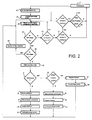
- Fig. 2 shows a flow diagram of the circuit and program logic of the device according to the invention.
- the circuit and program logic processes those transmitted by a caller over the telephone network 9 Numbers and characters and controls the device according to FIG. 1.
- the incoming DTMF signals are defined Frequency pairs (tones) recognized by the DTMF decoder 1.2 and binary forwarded encrypted to the circuit and program software will.
- the device After establishing a connection via the telephone network 9 The device initializes itself in program step 20 the processor 3.1 switches the tone generator 7 off via the feed line 3.6, sets the level of the level line 3.5 and the output lines 3.4 Zero, allows the device to be reset by the Circuit reset module 2 via control line 2.3 and deletes the content all registers of the processor 3.1.
- An initialization tone sequence is then sent in program step 21 with the aid of tone generator 7.
- the device is then ready to receive instructions over the telephone network 9.
- incoming signals provided they are DTMF signals, are converted into binary code by the DTMF decoder 1.2 and forwarded.
- the circuit reset module 2 checks in step 23 via branches 2.3 of input lines 1.3 whether the received signal is the signal for resetting the device, for example the DTMF signal for the # Button. If this is the case, the logic module 2.1 checks in step 24 whether the control signal is also present on the control line 1.4 or on the branch 2.4, ie that a caller is currently, for example, the one # Button pressed. If this is also the case, it is checked in step 25 whether the position of the switching element 2.2 allows the electronic circuit to be reset.
- a reset generally prevents and / or the processor 3.1 a reset prevented by program control, opens again in program step 22 an incoming DTMF signal is waiting.
- step 33 the selected microcomputers are successively or all the microcomputers 13, which via the reset elements 6 to the Outputs of the expander unit 4 are connected, reset, by encoding the numbers of the outputs one after the other via the output lines 3.4 are transmitted to the expander unit 4.
- the level line 3.5 is supplied with voltage.
- step 36 checks whether the sequence of digits is a valid one Output number of the expander unit 4 with associated microcomputer 13 designated. If this is the case, the binary code for the Microcomputer 13 via the output lines 3.4 to the expander unit 4 which transmit the voltage then present on the level line 3.5 amplified at the corresponding output and the microcomputer 13 with the help the reset element 6 resets. In steps 40 and 41, all Register deleted and an acknowledgment tone or an acknowledgment tone sequence analog sent to steps 34 and 35.
- connection can also automatically, after a Time period without signal input, cancel and then automatically a DTMF signal Send to device to reset.
Landscapes
- Engineering & Computer Science (AREA)
- Signal Processing (AREA)
- Theoretical Computer Science (AREA)
- Automation & Control Theory (AREA)
- Physics & Mathematics (AREA)
- General Engineering & Computer Science (AREA)
- General Physics & Mathematics (AREA)
- Computer Networks & Wireless Communication (AREA)
- Telephonic Communication Services (AREA)
- Computer And Data Communications (AREA)
- Power Sources (AREA)
- Selective Calling Equipment (AREA)
Abstract
Description


- Fig.1
- Vorrichtung zum fernbedienten Zurücksetzen von Mikrocomputern mit angeschlossenen Mikrocomputern und Netzzugangsgerät.
- Fig.2
- ein Flußdiagramm der Schaltungs- und Programmlogik der erfindungsgemäßen Vorrichtung nach Fig. 1
Claims (19)
- Vorrichtung zum fernbedienten Zurücksetzen von Rechenanlagen, insbesondere Mikrocomputern, bestehend aus einer Steuerkarte und wenigstens einem Resetelement (6), welches jeweils einem Mikrocomputer (13) zugeordnet ist, wobei die Steuerkarte an das Telefonnetz anschließbar ist, mit einem Eingangselement (1) über das Telefonnetz übermittelte Steuersignale empfängt und eine Zentraleinheit (3) die Steuersignale als binären Steuercode einer Expandereinheit (4) übermittelt, welche die dem Steuercode entsprechenden Resetelemente (6) ansteuert und schaltet, wodurch die zugeordneten Mikrocomputer (13) zurückgesetzt werden.
- Vorrichtung nach Anspruch 1, dadurch gekennzeichnet,
daß eine Netzzugangskontrolle mit Abfrage eines Zugangscodes vorgesehen ist, welche entweder innerhalb der Steuerkarte vom Eingangselement (1) oder von der Zentraleinheit (3) oder außerhalb der Steuerkarte von einem Vorschaltelement (8), welches zwischen Netzanschluß und Steuerkarte geschaltet ist, insbesondere von einem Netzzugangselement NAD, durchgeführt wird. - Vorrichtung nach Anspruch 1 oder 2, dadurch gekennzeichnet,
daß die Steuersignale mehrfrequenzcodierte (MFV-) Signale sind, welche innerhalb der Eingangseinheit (1) mit einem MFV-Decoder (1.2) in binäre Signale umwandelt und der Zentraleinheit übermittelt werden. - Vorrichtung nach Anspruch 3, dadurch gekennzeichnet,
daß der MFV-Decoder (1.2) über eine Steuerleitung (1.4) die Zentraleinheit freischaltet, falls am MFV-Decoder (1.2) ein gültiges MFV-Signal anliegt. - Vorrichtung nach Anspruch 2, dadurch gekennzeichnet,
daß die Steuerkarte eine RS232-Schnittstelle aufweist und über ein Modem als Vorschaltgerät (8), welches an die RS232-Schnittstelle angeschlossen ist, mit dem Telefonnetz verbunden ist. - Vorrichtung nach Anspruch 5, dadurch gekennzeichnet,
daß die Steuersignale Datenwörter sind. - Vorrichtung nach einem der vorherigen Ansprüche, dadurch gekennzeichnet,
daß ein Schaltungsresetmodul (2) die Steuerkarte und damit die Resetelemente (6) in einen definierten Anfangszustand zurückzusetzen imstande ist. - Vorrichtung nach einem der vorherigen Ansprüche, dadurch gekennzeichnet,
daß das Schaltungsresetmodul (2) die Steuerkarte nach richtiger Zugangscodeeingabe in den definierten Anfangszustand zurücksetzt. - Vorrichtung nach Anspruch 7 oder 8, dadurch gekennzeichnet,
daß das Schaltungsresetmodul (2) beim Absinken der Versorgungsspannung unter den für den Betrieb der Steuerkarte notwendigen Wert, z.B. bei unvollständigem Spannungsaufbau nach einem Stromausfall oder bei Spannungsschwankungen, die Zentraleinheit (3) zum Zurücksetzen der Steuerkarte in einen definierten Anfangszustand veranlaßt. - Vorrichtung nach einem der Ansprüche 7 bis 9, dadurch gekennzeichnet,
daß das Schaltungsresetmodul (2) bei Eingabe eines Resetsignals das von der Eingangseinheit (1) empfangen und dem Schaltungsresetmodul (2) über Leitungen (2.3) übermittelt wird, die Zentraleinheit (3) zum Zurücksetzen der Steuerkarte in einen definierten Anfangszustand veranlaßt. - Vorrichtung nach einem der Ansprüche 7 bis 10, dadurch gekennzeichnet,
daß das Schaltungsresetmodul (2) als Steuereinheit einen Logikbaustein (2.1) aus Gattern und Transistoren aufweist. - Vorrichtung nach einem der Ansprüche 7 bis 11, dadurch gekennzeichnet,
daß das Schaltungsresetmodul (2) wenigstens drei Betriebszustände einnehmen kann, wobei ein dem Schaltungsresetmodul (2) zugeordnetes Schaltelement (2.2) in einer Stellung A das Zurücksetzen der Steuerkarte immer verhindert, in einer zweiten Stellung B das Zurücksetzen immer erlaubt und in einer dritten Stellung C die Zentraleinheit (3) programmgesteuert ein Zurücksetzen der elektronischen Schaltung zuzulassen oder zu verhindern imstande ist. - Vorrichtung nach einem der vorherigen Ansprüche, dadurch gekennzeichnet,
daß die Zentraleinheit (3) einzelne, als Steuersignal in Form von MFV-Signalen oder Datenwörtern verschlüsselte, Ausgänge (4.2) der Expandereinheit (4) mit anschließbarem Resetelement (6) und damit den zugehörigen Mikrocomputer (13) anzusprechen imstande ist. - Vorrichtung nach einem der vorherigen Ansprüche, dadurch gekennzeichnet,
daß mehrere oder sämtliche Ausgänge (4.2) der Expandereinheit (4) durch die Eingabe eines Steuersignals auswählbar und die den Ausgängen (4.2) zugehörigen Mikrocomputer (13) zurücksetzbar sind. - Vorrichtung nach einem der vorherigen Ansprüche, dadurch gekennzeichnet,
daß ein Tongenerator (7) oder die Zentraleinheit (3) nach erfolgreicher Ausführung einer Anweisung einen Quittungston oder eine Quittungstonfolge bzw. ein Quittungs-Datenwort oder bei von der Zentraleinheit (3) erkannten fehlerhaften Anweisungen einen Fehlerton oder eine Fehlertonfolge bzw. ein Fehler-Datenwort über das Telefonnetz (9) zu senden imstande ist. - Vorrichtung nach einem der vorherigen Ansprüche, dadurch gekennzeichnet,
daß die Zentraleinheit (3) einen Prozessor (3.1) und eine Speichereinheit (3.2), vorzugsweise einen nichtflüchtigen Speicher, z.B. ein EPROM, aufweist, das ein Programm zur Steuerung der Steuerkarte enthält. - Vorrichtung nach einem der vorherigen Ansprüche, dadurch gekennzeichnet,
daß je ein Resetelement (6) an die Resetleitung des zugeordneten Mikrocomputers (13) angeschlossen ist, wobei ein Mikrocomputer beim Anliegen eines Signals am jeweiligen Resetelement zurückgesetzt wird (Warmstart). - Vorrichtung nach einem der Ansprüche 1 bis 16, dadurch gekennzeichnet,
daß die Resetelemente (6) ein Starkstromrelais enthalten und die Stromversorgung des dem Resetelement (6) zugeordneten Mikrocomputers (13) durch Schalten des Relais beim Anliegen eines Signals am Resetelement unterbrochen bzw. wiederhergestellt wird (Kaltstart). - Vorrichtung nach Anspruch 18, dadurch gekennzeichnet,
daß das Starkstromrelais eines Resetelements (6) mittels eines im Resetelement integrierten RS-Flipflops geschaltet wird, wobei jeweils zwei Ausgangsleitungen der Expandereinheit (4) mit den Eingangsleitungen des RS-Flipflops verbunden sind, so daß der Mikrocomputer (13) durch Ansteuerung der Ausgangsleitungen gezielt an- und ausschaltbar ist.
Applications Claiming Priority (2)
| Application Number | Priority Date | Filing Date | Title |
|---|---|---|---|
| DE19712372 | 1997-03-25 | ||
| DE19712372A DE19712372A1 (de) | 1997-03-25 | 1997-03-25 | Vorrichtung zum fernbedienten Zurücksetzen von Rechenanlagen, insbesondere Mikrocomputern |
Publications (3)
| Publication Number | Publication Date |
|---|---|
| EP0869638A2 true EP0869638A2 (de) | 1998-10-07 |
| EP0869638A3 EP0869638A3 (de) | 2004-09-01 |
| EP0869638B1 EP0869638B1 (de) | 2006-11-15 |
Family
ID=7824480
Family Applications (1)
| Application Number | Title | Priority Date | Filing Date |
|---|---|---|---|
| EP98103785A Expired - Lifetime EP0869638B1 (de) | 1997-03-25 | 1998-03-04 | Vorrichtung zum fernbedienten Zurücksetzen von Rechenanlagen, insbesondere Mikrocomputern |
Country Status (4)
| Country | Link |
|---|---|
| EP (1) | EP0869638B1 (de) |
| AT (1) | ATE345622T1 (de) |
| DE (2) | DE19712372A1 (de) |
| ES (1) | ES2275290T3 (de) |
Cited By (1)
| Publication number | Priority date | Publication date | Assignee | Title |
|---|---|---|---|---|
| EP1094382A1 (de) * | 1999-10-18 | 2001-04-25 | Sony Service Center (Europe) N.V. | Rücksetzvorrichtung und Steuerungssystem |
Families Citing this family (2)
| Publication number | Priority date | Publication date | Assignee | Title |
|---|---|---|---|---|
| DE10200460A1 (de) * | 2002-01-09 | 2003-07-24 | Peppercon Ag | Verfahren und Vorrichtung zur Fernsteuerung von Reset und Stromversorgung von Rechnern über Konsole-Video-Maus -Verlängerung (KVM-Extender) |
| DE10218209A1 (de) * | 2002-04-24 | 2003-11-06 | Deutsche Telekom Ag | Fernresetkarte für einen Personalcomputer |
Family Cites Families (7)
| Publication number | Priority date | Publication date | Assignee | Title |
|---|---|---|---|---|
| US4686526A (en) * | 1985-09-12 | 1987-08-11 | The United States Of America As Represented By The United States Department Of Energy | Remote reset circuit |
| US5086505A (en) * | 1989-06-30 | 1992-02-04 | Motorola, Inc. | Selective individual reset apparatus and method |
| US5333152A (en) * | 1989-09-22 | 1994-07-26 | Wilber James G | Electronic mail remote data transfer system |
| US5070450A (en) * | 1990-05-25 | 1991-12-03 | Dell Usa Corporation | Power on coordination system and method for multiple processors |
| GB2258118A (en) * | 1991-07-23 | 1993-01-27 | Simon Durrant | Remote telephone switch |
| JP2960818B2 (ja) * | 1992-07-09 | 1999-10-12 | 株式会社日立製作所 | プロセッサのリセット方式 |
| US5430865A (en) * | 1992-10-13 | 1995-07-04 | Astro Sciences Corporation | Hardware remote reset circuit |
-
1997
- 1997-03-25 DE DE19712372A patent/DE19712372A1/de not_active Withdrawn
-
1998
- 1998-03-04 ES ES98103785T patent/ES2275290T3/es not_active Expired - Lifetime
- 1998-03-04 EP EP98103785A patent/EP0869638B1/de not_active Expired - Lifetime
- 1998-03-04 AT AT98103785T patent/ATE345622T1/de active
- 1998-03-04 DE DE59813800T patent/DE59813800D1/de not_active Expired - Lifetime
Cited By (1)
| Publication number | Priority date | Publication date | Assignee | Title |
|---|---|---|---|---|
| EP1094382A1 (de) * | 1999-10-18 | 2001-04-25 | Sony Service Center (Europe) N.V. | Rücksetzvorrichtung und Steuerungssystem |
Also Published As
| Publication number | Publication date |
|---|---|
| ES2275290T3 (es) | 2007-06-01 |
| DE59813800D1 (de) | 2006-12-28 |
| DE19712372A1 (de) | 1998-10-01 |
| EP0869638B1 (de) | 2006-11-15 |
| EP0869638A3 (de) | 2004-09-01 |
| ATE345622T1 (de) | 2006-12-15 |
Similar Documents
| Publication | Publication Date | Title |
|---|---|---|
| DE2362344A1 (de) | Datenuebertragungsanlage | |
| DE2951550A1 (de) | Anordnung zur ferneinschaltung und fernabschaltung von elektrischen anlagen | |
| EP0693848A2 (de) | Kommunikationssystem | |
| DE19549014C1 (de) | Verfahren zum Aktivieren und Ausführen von gesicherten Funktionen in einem Kommunikationssystem | |
| DE2250014C3 (de) | Schaltungsanordnung zur Entgegennahme eines für eine Teilnehmerstelle bestimmten Anrufes durch eine andere Teilnehmerstelle in einer Fernsprechvermittlungsanlage | |
| EP0869638B1 (de) | Vorrichtung zum fernbedienten Zurücksetzen von Rechenanlagen, insbesondere Mikrocomputern | |
| DE2517525C3 (de) | Verfahren und Signalisierungsidentifizierer zum Erkennen von Fernmelde-Signalisierungskriterien | |
| EP0358597A2 (de) | Fernsprechvermittlungseinrichtung | |
| EP0658034B1 (de) | Schaltungsanordnung zur Anrufweiterleitung | |
| EP0603692B1 (de) | Verfahren zum automatischen Prüfen von Vermittlungs-und Uebertragungsvorgängen in einem Fernmeldenetz sowie eine Antwortstation zur Durchführung des Verfahrens | |
| EP0973344B1 (de) | Verfahren zum automatischen Bereitstellen von Informationen über Leistungsmerkmale einer Kommunikationsendeinrichtung | |
| DE2155079C3 (de) | Notüberwachungseinrichtung für eine elektronische Vermittlungseinrichtung | |
| DE19542948C2 (de) | Verfahren für die Kommunikation eines externen Rechners über ein Telekommunikations-Endgerät mit einem Telekommunikationsnetz und Telekommunikations-Endgerät | |
| EP1082647A2 (de) | Programmgesteuerte vorrichtung | |
| EP0460403B1 (de) | Verfahren für Datenübertragungen in Kommunikations-Vermittlungsanlagen | |
| DE10253374B4 (de) | Einwahlsperre für Datenübertragungseinrichtungen | |
| DE10225767A1 (de) | Elektrisches Überwachungsgerät | |
| DE3330889A1 (de) | Schaltungsanordnung zur ueberpruefung der funktionstuechtigkeit einer rechnergesteuerten fernsprechvermittlungsanlage | |
| EP0673142A2 (de) | Telekommunikationsendgerät | |
| DE2829897C2 (de) | Verfahren zur Freischaltung von peripheren Einrichtungen und/oder von Verbindungen in einer mit gespeicherten Programmen zentral gesteuerten Vermittlungseinrichtung | |
| DE1934273A1 (de) | Datenuebertragungsanlage | |
| DE3216785C2 (de) | Verfahren zur Abschaltung von Wahlumsetzeinrichtungen in Fernmelde-, insbesondere Fernsprechanlagen | |
| EP1298898A2 (de) | Verfahren zum Konfigurieren einer Anlage mit mehreren Peripheriebaugruppen sowie Anlage und Steckverbinder zur Realisierung des Verfahrens | |
| DE10144522A1 (de) | Umschalteinrichtung zum Umschalten zwischen Telekommunikationsanlagen | |
| DE3123614A1 (de) | Verfahren und schaltungsanordnung zur ferngesteuerten umschaltung von teilnehmeranschluessen auf einer ansageeinrichtung |
Legal Events
| Date | Code | Title | Description |
|---|---|---|---|
| PUAI | Public reference made under article 153(3) epc to a published international application that has entered the european phase |
Free format text: ORIGINAL CODE: 0009012 |
|
| AK | Designated contracting states |
Kind code of ref document: A2 Designated state(s): AT BE CH DE DK ES FI FR GB GR IE IT LI LU MC NL PT SE |
|
| PUAL | Search report despatched |
Free format text: ORIGINAL CODE: 0009013 |
|
| AK | Designated contracting states |
Kind code of ref document: A3 Designated state(s): AT BE CH DE DK ES FI FR GB GR IE IT LI LU MC NL PT SE |
|
| AX | Request for extension of the european patent |
Extension state: AL LT LV MK RO SI |
|
| 17P | Request for examination filed |
Effective date: 20050301 |
|
| AKX | Designation fees paid |
Designated state(s): AT BE CH DE DK ES FI FR GB GR IE IT LI LU MC NL PT SE |
|
| 17Q | First examination report despatched |
Effective date: 20050502 |
|
| GRAP | Despatch of communication of intention to grant a patent |
Free format text: ORIGINAL CODE: EPIDOSNIGR1 |
|
| GRAS | Grant fee paid |
Free format text: ORIGINAL CODE: EPIDOSNIGR3 |
|
| GRAA | (expected) grant |
Free format text: ORIGINAL CODE: 0009210 |
|
| AK | Designated contracting states |
Kind code of ref document: B1 Designated state(s): AT BE CH DE DK ES FI FR GB GR IE IT LI LU MC NL PT SE |
|
| PG25 | Lapsed in a contracting state [announced via postgrant information from national office to epo] |
Ref country code: FI Free format text: LAPSE BECAUSE OF FAILURE TO SUBMIT A TRANSLATION OF THE DESCRIPTION OR TO PAY THE FEE WITHIN THE PRESCRIBED TIME-LIMIT Effective date: 20061115 |
|
| REG | Reference to a national code |
Ref country code: GB Ref legal event code: FG4D Free format text: NOT ENGLISH |
|
| REG | Reference to a national code |
Ref country code: CH Ref legal event code: EP |
|
| REF | Corresponds to: |
Ref document number: 59813800 Country of ref document: DE Date of ref document: 20061228 Kind code of ref document: P |
|
| REG | Reference to a national code |
Ref country code: CH Ref legal event code: NV Representative=s name: ISLER & PEDRAZZINI AG Ref country code: IE Ref legal event code: FG4D Free format text: LANGUAGE OF EP DOCUMENT: GERMAN |
|
| PG25 | Lapsed in a contracting state [announced via postgrant information from national office to epo] |
Ref country code: SE Free format text: LAPSE BECAUSE OF FAILURE TO SUBMIT A TRANSLATION OF THE DESCRIPTION OR TO PAY THE FEE WITHIN THE PRESCRIBED TIME-LIMIT Effective date: 20070215 Ref country code: DK Free format text: LAPSE BECAUSE OF FAILURE TO SUBMIT A TRANSLATION OF THE DESCRIPTION OR TO PAY THE FEE WITHIN THE PRESCRIBED TIME-LIMIT Effective date: 20070215 |
|
| GBT | Gb: translation of ep patent filed (gb section 77(6)(a)/1977) |
Effective date: 20070129 |
|
| PG25 | Lapsed in a contracting state [announced via postgrant information from national office to epo] |
Ref country code: PT Free format text: LAPSE BECAUSE OF FAILURE TO SUBMIT A TRANSLATION OF THE DESCRIPTION OR TO PAY THE FEE WITHIN THE PRESCRIBED TIME-LIMIT Effective date: 20070416 |
|
| ET | Fr: translation filed | ||
| REG | Reference to a national code |
Ref country code: ES Ref legal event code: FG2A Ref document number: 2275290 Country of ref document: ES Kind code of ref document: T3 |
|
| PLBE | No opposition filed within time limit |
Free format text: ORIGINAL CODE: 0009261 |
|
| STAA | Information on the status of an ep patent application or granted ep patent |
Free format text: STATUS: NO OPPOSITION FILED WITHIN TIME LIMIT |
|
| REG | Reference to a national code |
Ref country code: CH Ref legal event code: PCAR Free format text: ISLER & PEDRAZZINI AG;POSTFACH 1772;8027 ZUERICH (CH) |
|
| 26N | No opposition filed |
Effective date: 20070817 |
|
| PG25 | Lapsed in a contracting state [announced via postgrant information from national office to epo] |
Ref country code: MC Free format text: LAPSE BECAUSE OF NON-PAYMENT OF DUE FEES Effective date: 20070331 |
|
| PG25 | Lapsed in a contracting state [announced via postgrant information from national office to epo] |
Ref country code: GR Free format text: LAPSE BECAUSE OF FAILURE TO SUBMIT A TRANSLATION OF THE DESCRIPTION OR TO PAY THE FEE WITHIN THE PRESCRIBED TIME-LIMIT Effective date: 20070216 |
|
| PG25 | Lapsed in a contracting state [announced via postgrant information from national office to epo] |
Ref country code: LU Free format text: LAPSE BECAUSE OF NON-PAYMENT OF DUE FEES Effective date: 20070304 |
|
| REG | Reference to a national code |
Ref country code: FR Ref legal event code: PLFP Year of fee payment: 19 |
|
| PGFP | Annual fee paid to national office [announced via postgrant information from national office to epo] |
Ref country code: ES Payment date: 20160322 Year of fee payment: 19 Ref country code: CH Payment date: 20160322 Year of fee payment: 19 Ref country code: IE Payment date: 20160322 Year of fee payment: 19 |
|
| PGFP | Annual fee paid to national office [announced via postgrant information from national office to epo] |
Ref country code: BE Payment date: 20160322 Year of fee payment: 19 Ref country code: AT Payment date: 20160318 Year of fee payment: 19 |
|
| PGFP | Annual fee paid to national office [announced via postgrant information from national office to epo] |
Ref country code: IT Payment date: 20160318 Year of fee payment: 19 |
|
| REG | Reference to a national code |
Ref country code: FR Ref legal event code: PLFP Year of fee payment: 20 |
|
| PGFP | Annual fee paid to national office [announced via postgrant information from national office to epo] |
Ref country code: DE Payment date: 20170327 Year of fee payment: 20 Ref country code: NL Payment date: 20170323 Year of fee payment: 20 Ref country code: FR Payment date: 20170323 Year of fee payment: 20 |
|
| PGFP | Annual fee paid to national office [announced via postgrant information from national office to epo] |
Ref country code: GB Payment date: 20170327 Year of fee payment: 20 |
|
| REG | Reference to a national code |
Ref country code: CH Ref legal event code: PL |
|
| REG | Reference to a national code |
Ref country code: AT Ref legal event code: MM01 Ref document number: 345622 Country of ref document: AT Kind code of ref document: T Effective date: 20170304 |
|
| REG | Reference to a national code |
Ref country code: IE Ref legal event code: MM4A |
|
| PG25 | Lapsed in a contracting state [announced via postgrant information from national office to epo] |
Ref country code: AT Free format text: LAPSE BECAUSE OF NON-PAYMENT OF DUE FEES Effective date: 20170304 |
|
| PG25 | Lapsed in a contracting state [announced via postgrant information from national office to epo] |
Ref country code: LI Free format text: LAPSE BECAUSE OF NON-PAYMENT OF DUE FEES Effective date: 20170331 Ref country code: IT Free format text: LAPSE BECAUSE OF NON-PAYMENT OF DUE FEES Effective date: 20170304 Ref country code: IE Free format text: LAPSE BECAUSE OF NON-PAYMENT OF DUE FEES Effective date: 20170304 Ref country code: CH Free format text: LAPSE BECAUSE OF NON-PAYMENT OF DUE FEES Effective date: 20170331 |
|
| REG | Reference to a national code |
Ref country code: DE Ref legal event code: R071 Ref document number: 59813800 Country of ref document: DE |
|
| REG | Reference to a national code |
Ref country code: BE Ref legal event code: MM Effective date: 20170331 Ref country code: NL Ref legal event code: MK Effective date: 20180303 |
|
| REG | Reference to a national code |
Ref country code: GB Ref legal event code: PE20 Expiry date: 20180303 |
|
| PG25 | Lapsed in a contracting state [announced via postgrant information from national office to epo] |
Ref country code: GB Free format text: LAPSE BECAUSE OF EXPIRATION OF PROTECTION Effective date: 20180303 |
|
| REG | Reference to a national code |
Ref country code: ES Ref legal event code: FD2A Effective date: 20180507 |
|
| PG25 | Lapsed in a contracting state [announced via postgrant information from national office to epo] |
Ref country code: BE Free format text: LAPSE BECAUSE OF NON-PAYMENT OF DUE FEES Effective date: 20170331 |
|
| PG25 | Lapsed in a contracting state [announced via postgrant information from national office to epo] |
Ref country code: ES Free format text: LAPSE BECAUSE OF NON-PAYMENT OF DUE FEES Effective date: 20170305 |