EP0869841B1 - Schaumstoffherstellungsvorrichtung - Google Patents
Schaumstoffherstellungsvorrichtung Download PDFInfo
- Publication number
- EP0869841B1 EP0869841B1 EP97931836A EP97931836A EP0869841B1 EP 0869841 B1 EP0869841 B1 EP 0869841B1 EP 97931836 A EP97931836 A EP 97931836A EP 97931836 A EP97931836 A EP 97931836A EP 0869841 B1 EP0869841 B1 EP 0869841B1
- Authority
- EP
- European Patent Office
- Prior art keywords
- venturi
- nozzle
- gas
- liquid
- foam
- Prior art date
- Legal status (The legal status is an assumption and is not a legal conclusion. Google has not performed a legal analysis and makes no representation as to the accuracy of the status listed.)
- Expired - Lifetime
Links
- 239000006260 foam Substances 0.000 title claims abstract description 42
- 239000007789 gas Substances 0.000 claims abstract description 59
- 239000007788 liquid Substances 0.000 claims abstract description 36
- 238000002156 mixing Methods 0.000 claims abstract description 18
- 230000000694 effects Effects 0.000 claims abstract description 15
- 239000012071 phase Substances 0.000 claims abstract description 8
- 239000007791 liquid phase Substances 0.000 claims abstract description 3
- 239000007792 gaseous phase Substances 0.000 claims abstract 2
- 238000002604 ultrasonography Methods 0.000 claims description 2
- 230000000750 progressive effect Effects 0.000 abstract description 3
- 238000003780 insertion Methods 0.000 abstract 1
- 230000037431 insertion Effects 0.000 abstract 1
- 239000012530 fluid Substances 0.000 description 31
- 239000000203 mixture Substances 0.000 description 25
- 230000003068 static effect Effects 0.000 description 14
- 239000004094 surface-active agent Substances 0.000 description 13
- 230000009471 action Effects 0.000 description 11
- 230000015572 biosynthetic process Effects 0.000 description 11
- 238000004519 manufacturing process Methods 0.000 description 10
- 239000006185 dispersion Substances 0.000 description 6
- 239000000839 emulsion Substances 0.000 description 6
- 238000000034 method Methods 0.000 description 6
- 230000008569 process Effects 0.000 description 6
- 238000002485 combustion reaction Methods 0.000 description 5
- 238000005187 foaming Methods 0.000 description 5
- 239000002904 solvent Substances 0.000 description 5
- 238000011144 upstream manufacturing Methods 0.000 description 5
- 230000000739 chaotic effect Effects 0.000 description 4
- 230000007423 decrease Effects 0.000 description 4
- 230000035939 shock Effects 0.000 description 4
- 239000007864 aqueous solution Substances 0.000 description 3
- 230000008901 benefit Effects 0.000 description 3
- 150000001875 compounds Chemical class 0.000 description 3
- 230000003247 decreasing effect Effects 0.000 description 3
- 150000008040 ionic compounds Chemical class 0.000 description 3
- 230000033001 locomotion Effects 0.000 description 3
- 238000006386 neutralization reaction Methods 0.000 description 3
- 238000005381 potential energy Methods 0.000 description 3
- 239000000243 solution Substances 0.000 description 3
- 239000000126 substance Substances 0.000 description 3
- IJGRMHOSHXDMSA-UHFFFAOYSA-N Atomic nitrogen Chemical compound N#N IJGRMHOSHXDMSA-UHFFFAOYSA-N 0.000 description 2
- 102000004190 Enzymes Human genes 0.000 description 2
- 108090000790 Enzymes Proteins 0.000 description 2
- GQPLMRYTRLFLPF-UHFFFAOYSA-N Nitrous Oxide Chemical compound [O-][N+]#N GQPLMRYTRLFLPF-UHFFFAOYSA-N 0.000 description 2
- 239000004480 active ingredient Substances 0.000 description 2
- 239000000443 aerosol Substances 0.000 description 2
- 238000013459 approach Methods 0.000 description 2
- 230000008033 biological extinction Effects 0.000 description 2
- 230000033228 biological regulation Effects 0.000 description 2
- 238000006243 chemical reaction Methods 0.000 description 2
- 230000006835 compression Effects 0.000 description 2
- 238000007906 compression Methods 0.000 description 2
- 239000002537 cosmetic Substances 0.000 description 2
- 230000008878 coupling Effects 0.000 description 2
- 238000010168 coupling process Methods 0.000 description 2
- 238000005859 coupling reaction Methods 0.000 description 2
- 239000003599 detergent Substances 0.000 description 2
- 238000009792 diffusion process Methods 0.000 description 2
- 230000008034 disappearance Effects 0.000 description 2
- 235000013305 food Nutrition 0.000 description 2
- 239000000463 material Substances 0.000 description 2
- 239000002184 metal Substances 0.000 description 2
- 229910052751 metal Inorganic materials 0.000 description 2
- 239000000843 powder Substances 0.000 description 2
- 239000002243 precursor Substances 0.000 description 2
- 230000009467 reduction Effects 0.000 description 2
- XLYOFNOQVPJJNP-UHFFFAOYSA-N water Substances O XLYOFNOQVPJJNP-UHFFFAOYSA-N 0.000 description 2
- 241000195940 Bryophyta Species 0.000 description 1
- 229910001018 Cast iron Inorganic materials 0.000 description 1
- 229920004449 Halon® Polymers 0.000 description 1
- CBENFWSGALASAD-UHFFFAOYSA-N Ozone Chemical compound [O-][O+]=O CBENFWSGALASAD-UHFFFAOYSA-N 0.000 description 1
- 229910000831 Steel Inorganic materials 0.000 description 1
- 240000008042 Zea mays Species 0.000 description 1
- 230000006978 adaptation Effects 0.000 description 1
- 229910045601 alloy Inorganic materials 0.000 description 1
- 239000000956 alloy Substances 0.000 description 1
- 238000000889 atomisation Methods 0.000 description 1
- 238000004140 cleaning Methods 0.000 description 1
- 230000007547 defect Effects 0.000 description 1
- 230000001419 dependent effect Effects 0.000 description 1
- 230000006866 deterioration Effects 0.000 description 1
- PXBRQCKWGAHEHS-UHFFFAOYSA-N dichlorodifluoromethane Chemical compound FC(F)(Cl)Cl PXBRQCKWGAHEHS-UHFFFAOYSA-N 0.000 description 1
- 230000037213 diet Effects 0.000 description 1
- 235000005911 diet Nutrition 0.000 description 1
- 238000007865 diluting Methods 0.000 description 1
- 238000009826 distribution Methods 0.000 description 1
- 239000000446 fuel Substances 0.000 description 1
- 239000008240 homogeneous mixture Substances 0.000 description 1
- 238000000265 homogenisation Methods 0.000 description 1
- 238000007654 immersion Methods 0.000 description 1
- 230000006872 improvement Effects 0.000 description 1
- 235000011929 mousse Nutrition 0.000 description 1
- 230000007935 neutral effect Effects 0.000 description 1
- 229910052757 nitrogen Inorganic materials 0.000 description 1
- 239000001272 nitrous oxide Substances 0.000 description 1
- 239000003921 oil Substances 0.000 description 1
- 238000005457 optimization Methods 0.000 description 1
- 230000036961 partial effect Effects 0.000 description 1
- 230000000704 physical effect Effects 0.000 description 1
- 230000001737 promoting effect Effects 0.000 description 1
- 102000004169 proteins and genes Human genes 0.000 description 1
- 108090000623 proteins and genes Proteins 0.000 description 1
- 230000002829 reductive effect Effects 0.000 description 1
- 230000015227 regulation of liquid surface tension Effects 0.000 description 1
- 230000000717 retained effect Effects 0.000 description 1
- 238000011012 sanitization Methods 0.000 description 1
- 238000005507 spraying Methods 0.000 description 1
- 230000006641 stabilisation Effects 0.000 description 1
- 238000011105 stabilization Methods 0.000 description 1
- 239000010959 steel Substances 0.000 description 1
- 230000009466 transformation Effects 0.000 description 1
- 238000005406 washing Methods 0.000 description 1
Images


Classifications
-
- B—PERFORMING OPERATIONS; TRANSPORTING
- B05—SPRAYING OR ATOMISING IN GENERAL; APPLYING FLUENT MATERIALS TO SURFACES, IN GENERAL
- B05B—SPRAYING APPARATUS; ATOMISING APPARATUS; NOZZLES
- B05B7/00—Spraying apparatus for discharge of liquids or other fluent materials from two or more sources, e.g. of liquid and air, of powder and gas
- B05B7/0018—Spraying apparatus for discharge of liquids or other fluent materials from two or more sources, e.g. of liquid and air, of powder and gas with devices for making foam
-
- B—PERFORMING OPERATIONS; TRANSPORTING
- B01—PHYSICAL OR CHEMICAL PROCESSES OR APPARATUS IN GENERAL
- B01F—MIXING, e.g. DISSOLVING, EMULSIFYING OR DISPERSING
- B01F25/00—Flow mixers; Mixers for falling materials, e.g. solid particles
- B01F25/30—Injector mixers
- B01F25/31—Injector mixers in conduits or tubes through which the main component flows
-
- B—PERFORMING OPERATIONS; TRANSPORTING
- B01—PHYSICAL OR CHEMICAL PROCESSES OR APPARATUS IN GENERAL
- B01F—MIXING, e.g. DISSOLVING, EMULSIFYING OR DISPERSING
- B01F25/00—Flow mixers; Mixers for falling materials, e.g. solid particles
- B01F25/30—Injector mixers
- B01F25/31—Injector mixers in conduits or tubes through which the main component flows
- B01F25/311—Injector mixers in conduits or tubes through which the main component flows for mixing more than two components; Devices specially adapted for generating foam
- B01F25/3111—Devices specially adapted for generating foam, e.g. air foam
-
- B—PERFORMING OPERATIONS; TRANSPORTING
- B01—PHYSICAL OR CHEMICAL PROCESSES OR APPARATUS IN GENERAL
- B01F—MIXING, e.g. DISSOLVING, EMULSIFYING OR DISPERSING
- B01F25/00—Flow mixers; Mixers for falling materials, e.g. solid particles
- B01F25/30—Injector mixers
- B01F25/31—Injector mixers in conduits or tubes through which the main component flows
- B01F25/312—Injector mixers in conduits or tubes through which the main component flows with Venturi elements; Details thereof
- B01F25/3124—Injector mixers in conduits or tubes through which the main component flows with Venturi elements; Details thereof characterised by the place of introduction of the main flow
- B01F25/31241—Injector mixers in conduits or tubes through which the main component flows with Venturi elements; Details thereof characterised by the place of introduction of the main flow the main flow being injected in the circumferential area of the venturi, creating an aspiration in the central part of the conduit
-
- B—PERFORMING OPERATIONS; TRANSPORTING
- B01—PHYSICAL OR CHEMICAL PROCESSES OR APPARATUS IN GENERAL
- B01F—MIXING, e.g. DISSOLVING, EMULSIFYING OR DISPERSING
- B01F25/00—Flow mixers; Mixers for falling materials, e.g. solid particles
- B01F25/30—Injector mixers
- B01F25/31—Injector mixers in conduits or tubes through which the main component flows
- B01F25/312—Injector mixers in conduits or tubes through which the main component flows with Venturi elements; Details thereof
- B01F25/3124—Injector mixers in conduits or tubes through which the main component flows with Venturi elements; Details thereof characterised by the place of introduction of the main flow
- B01F25/31243—Eductor or eductor-type venturi, i.e. the main flow being injected through the venturi with high speed in the form of a jet
-
- B—PERFORMING OPERATIONS; TRANSPORTING
- B01—PHYSICAL OR CHEMICAL PROCESSES OR APPARATUS IN GENERAL
- B01F—MIXING, e.g. DISSOLVING, EMULSIFYING OR DISPERSING
- B01F25/00—Flow mixers; Mixers for falling materials, e.g. solid particles
- B01F25/30—Injector mixers
- B01F25/31—Injector mixers in conduits or tubes through which the main component flows
- B01F25/312—Injector mixers in conduits or tubes through which the main component flows with Venturi elements; Details thereof
- B01F25/3125—Injector mixers in conduits or tubes through which the main component flows with Venturi elements; Details thereof characteristics of the Venturi parts
- B01F25/31253—Discharge
- B01F25/312533—Constructional characteristics of the diverging discharge conduit or barrel, e.g. with zones of changing conicity
-
- B—PERFORMING OPERATIONS; TRANSPORTING
- B01—PHYSICAL OR CHEMICAL PROCESSES OR APPARATUS IN GENERAL
- B01F—MIXING, e.g. DISSOLVING, EMULSIFYING OR DISPERSING
- B01F31/00—Mixers with shaking, oscillating, or vibrating mechanisms
- B01F31/80—Mixing by means of high-frequency vibrations above one kHz, e.g. ultrasonic vibrations
- B01F31/86—Mixing by means of high-frequency vibrations above one kHz, e.g. ultrasonic vibrations with vibration of the receptacle or part of it
-
- B—PERFORMING OPERATIONS; TRANSPORTING
- B05—SPRAYING OR ATOMISING IN GENERAL; APPLYING FLUENT MATERIALS TO SURFACES, IN GENERAL
- B05B—SPRAYING APPARATUS; ATOMISING APPARATUS; NOZZLES
- B05B7/00—Spraying apparatus for discharge of liquids or other fluent materials from two or more sources, e.g. of liquid and air, of powder and gas
- B05B7/02—Spray pistols; Apparatus for discharge
- B05B7/04—Spray pistols; Apparatus for discharge with arrangements for mixing liquids or other fluent materials before discharge
- B05B7/0416—Spray pistols; Apparatus for discharge with arrangements for mixing liquids or other fluent materials before discharge with arrangements for mixing one gas and one liquid
- B05B7/0425—Spray pistols; Apparatus for discharge with arrangements for mixing liquids or other fluent materials before discharge with arrangements for mixing one gas and one liquid without any source of compressed gas, e.g. the air being sucked by the pressurised liquid
-
- B—PERFORMING OPERATIONS; TRANSPORTING
- B05—SPRAYING OR ATOMISING IN GENERAL; APPLYING FLUENT MATERIALS TO SURFACES, IN GENERAL
- B05B—SPRAYING APPARATUS; ATOMISING APPARATUS; NOZZLES
- B05B7/00—Spraying apparatus for discharge of liquids or other fluent materials from two or more sources, e.g. of liquid and air, of powder and gas
- B05B7/02—Spray pistols; Apparatus for discharge
- B05B7/04—Spray pistols; Apparatus for discharge with arrangements for mixing liquids or other fluent materials before discharge
- B05B7/0416—Spray pistols; Apparatus for discharge with arrangements for mixing liquids or other fluent materials before discharge with arrangements for mixing one gas and one liquid
- B05B7/0441—Spray pistols; Apparatus for discharge with arrangements for mixing liquids or other fluent materials before discharge with arrangements for mixing one gas and one liquid with one inner conduit of liquid surrounded by an external conduit of gas upstream the mixing chamber
- B05B7/0458—Spray pistols; Apparatus for discharge with arrangements for mixing liquids or other fluent materials before discharge with arrangements for mixing one gas and one liquid with one inner conduit of liquid surrounded by an external conduit of gas upstream the mixing chamber the gas and liquid flows being perpendicular just upstream the mixing chamber
-
- B—PERFORMING OPERATIONS; TRANSPORTING
- B05—SPRAYING OR ATOMISING IN GENERAL; APPLYING FLUENT MATERIALS TO SURFACES, IN GENERAL
- B05B—SPRAYING APPARATUS; ATOMISING APPARATUS; NOZZLES
- B05B7/00—Spraying apparatus for discharge of liquids or other fluent materials from two or more sources, e.g. of liquid and air, of powder and gas
- B05B7/24—Spraying apparatus for discharge of liquids or other fluent materials from two or more sources, e.g. of liquid and air, of powder and gas with means, e.g. a container, for supplying liquid or other fluent material to a discharge device
- B05B7/2489—Spraying apparatus for discharge of liquids or other fluent materials from two or more sources, e.g. of liquid and air, of powder and gas with means, e.g. a container, for supplying liquid or other fluent material to a discharge device an atomising fluid, e.g. a gas, being supplied to the discharge device
- B05B7/2494—Spraying apparatus for discharge of liquids or other fluent materials from two or more sources, e.g. of liquid and air, of powder and gas with means, e.g. a container, for supplying liquid or other fluent material to a discharge device an atomising fluid, e.g. a gas, being supplied to the discharge device a liquid being supplied from a pressurized or compressible container to the discharge device
-
- B—PERFORMING OPERATIONS; TRANSPORTING
- B01—PHYSICAL OR CHEMICAL PROCESSES OR APPARATUS IN GENERAL
- B01F—MIXING, e.g. DISSOLVING, EMULSIFYING OR DISPERSING
- B01F23/00—Mixing according to the phases to be mixed, e.g. dispersing or emulsifying
- B01F23/20—Mixing gases with liquids
- B01F23/23—Mixing gases with liquids by introducing gases into liquid media, e.g. for producing aerated liquids
- B01F23/235—Mixing gases with liquids by introducing gases into liquid media, e.g. for producing aerated liquids for making foam
-
- B—PERFORMING OPERATIONS; TRANSPORTING
- B05—SPRAYING OR ATOMISING IN GENERAL; APPLYING FLUENT MATERIALS TO SURFACES, IN GENERAL
- B05B—SPRAYING APPARATUS; ATOMISING APPARATUS; NOZZLES
- B05B17/00—Apparatus for spraying or atomising liquids or other fluent materials, not covered by the preceding groups
- B05B17/04—Apparatus for spraying or atomising liquids or other fluent materials, not covered by the preceding groups operating with special methods
- B05B17/06—Apparatus for spraying or atomising liquids or other fluent materials, not covered by the preceding groups operating with special methods using ultrasonic or other kinds of vibrations
-
- Y—GENERAL TAGGING OF NEW TECHNOLOGICAL DEVELOPMENTS; GENERAL TAGGING OF CROSS-SECTIONAL TECHNOLOGIES SPANNING OVER SEVERAL SECTIONS OF THE IPC; TECHNICAL SUBJECTS COVERED BY FORMER USPC CROSS-REFERENCE ART COLLECTIONS [XRACs] AND DIGESTS
- Y10—TECHNICAL SUBJECTS COVERED BY FORMER USPC
- Y10S—TECHNICAL SUBJECTS COVERED BY FORMER USPC CROSS-REFERENCE ART COLLECTIONS [XRACs] AND DIGESTS
- Y10S261/00—Gas and liquid contact apparatus
- Y10S261/26—Foam
-
- Y—GENERAL TAGGING OF NEW TECHNOLOGICAL DEVELOPMENTS; GENERAL TAGGING OF CROSS-SECTIONAL TECHNOLOGIES SPANNING OVER SEVERAL SECTIONS OF THE IPC; TECHNICAL SUBJECTS COVERED BY FORMER USPC CROSS-REFERENCE ART COLLECTIONS [XRACs] AND DIGESTS
- Y10—TECHNICAL SUBJECTS COVERED BY FORMER USPC
- Y10S—TECHNICAL SUBJECTS COVERED BY FORMER USPC CROSS-REFERENCE ART COLLECTIONS [XRACs] AND DIGESTS
- Y10S261/00—Gas and liquid contact apparatus
- Y10S261/75—Flowing liquid aspirates gas
Definitions
- the subject of the present invention is a device for generating foam and a apparatus for producing a foam, an aerosol, an emulsion or bubbles, comprising a liquid introduction nozzle, coaxial with a venturi stage comprising a convergent disposed opposite the nozzle, and a gas inlet coaxial to the corresponding nozzle with the convergent and a divergent.
- Foam production systems are used, for example, to apply an active product to a surface to be cleaned, degrease, sanitize, depollute, chemically deactivate or neutralize.
- Foam generation systems have evolved in recent years with the introduction of systems allowing, in particular, the simultaneous introduction of gas and liquid in a liquid-gas-liquid dispersion space which can be adjustable to modify the proportion of gas introduced as described in WO 9531287. Even if the proportion of gas can thus be significant, there is no action of division of the bubbles by cavitation and their size remains visible to the eye bare.
- US 5085371 describes a training device foam as presented in the preamble of claim 1.
- the foam is always formed after leaving the system, which induces the formation of bubbles under atmospheric static pressure and therefore large bubble dimensions and the surface of contact and the surfactant activity of the foam cannot be optimized.
- the outlet nozzle is adapted to atomize the fluid by increasing the parameters of pressure and speed of the fluid, which leads to a lowering of the static pressure, the potential energy of the static pressure being thus transformed into kinetic energy.
- the subject of the present invention is the formation of a foam of minimum density, as homogeneous as possible, using the cavitation phenomenon that was avoided in the prior art.
- the system operation values are greater than 90% volume gas in the final mixture.
- the device for forming foam by Venturi effect, mixing a product in the liquid phase and a product in the gas phase comprising a liquid introduction nozzle, coaxial with a venturi stage comprising a convergent arranged opposite the nozzle, the neck of which is of diameter "D" and a gas inlet coaxial to the corresponding nozzle with the convergent, the gas being sucked in by effect venturi in a divergent and directed on a mixing chamber connected to a foam outlet, is characterized in that the divergent part of the venturi comprises at at least two zones of progressive taper with breaks between the zones, causing with the determined shape of the venturi cavitation and leads to a turbulence chamber.
- the device uses the difference in kinetic energy between that of the incident liquid jet free emitted by the nozzle, causing a conical dispersion which comes into contact with the neck diameter convergent "D" which decreases the speed of the liquid-gas mixture by lowering its pressure, and that of the liquid-gas mixture, to lower pressure, stored as potential energy in the gas bubbles during suction in the jet and compression in the convergent of the venturi.
- This energy is released in the form of cavitation energy in the divergent part of the venturi comprising sections of progressive taper which creates the phenomenon of cavitation due to excess gas in the liquid, associated with increased pressure static and decreasing the speed of the fluid in the divergent and in the chamber turbulence arranged downstream of the divergent.
- the present invention uses a nozzle creating a free jet of low taper, a neck convergent adapted to the size of this jet followed by a divergent.
- the set allows to create a gas suction upstream of the neck by Venturi effect and to create with the gas thus sucked in the conditions of cavitation on the walls of said divergent.
- this divergent form forms an inlet wall and creation of turbulence for a turbulence chamber.
- Said chamber can advantageously be equipped with a device allowing excite the mixture it contains with ultrasonic waves in the turbulence.
- An object of the present invention is a device for producing low foam. density, therefore containing a high proportion of gas and a large contact surface with the surface on which it is dispersed at the outlet of the system. She uses the forces generated by cavitating depressions, even when controlled in a stabilization chamber, to atomize the liquid by spraying it.
- the present invention further relates to an autonomous apparatus for generating foam using the above device, which achieves uniformity and reduced dimensions of bubbles allowing the active product to have a surface of contact and action taken to levels never reached by production of conventional foam.
- Another object of the present invention is the production of a two-phase mixture in which the size of the bubbles is as small as possible, that is to say in all case of diameter less than 20 microns.
- the coupling of cavitation, of flow turbulent and possibly the supply of energy in the form of ultrasound allows a maximum division of gas bubbles present in the fluid and the formation of a stable foam at the outlet of said chamber.
- the device in addition to the formation of foam makes it possible to mix and dose an incident fluid under pressure with a gas aspirated, generate bubbles, aerosols or emulsions.
- the system is perfectly adapted if the vacuum measured upstream of the neck of said nozzle outside the free high-pressure incident jet is, (by example), greater than 1 bar or more generally close to the maximum for the fluid considered.
- the distance between the nozzle outlet and the neck has an influence on the size gas cavities admitted into the Venturi and the quantity of gas admitted, it will be according to the invention between 2.d and 20.d (if we call “d" the outlet diameter of the nozzle), the diameter D of the neck will be between the length of said free jet between 1.d and 4.d.
- a nozzle 1 is adapted to disperse a fluid according to the determined flow and pressure parameters according to a cone of angle at the summit of low value ( ⁇ 20 °) and receives the fluid under a high inlet pressure through a supply channel 9.
- a value of 100 bars for information but not limitation; values included between 20 and 500 bars which can be specific in various applications.
- the active element includes two generators of ultrasonic waves 10 positioned radially on the turbulence chamber 4.
- the divergent comprises three zones of increasing conicities 14, 15, 16, the first zone 14 having an angle ⁇ 1 of between 0 and 10 °.
- the second zone 15 has an angle ⁇ 2 at least 5 ° greater than the angle ⁇ 1 presented by the first area, so that the area dividing lines are located at distances between 2D and 4D for line 14.15, and between 5D and 8D for line 15, 16 with respect to the line X, 14, materializing the exit from the neck X of 0 ° taper.
- the third zone 16 has an apex angle ⁇ 3 at least 15 ° greater than the value of the angle ⁇ 1 and less than the value of the angle ⁇ 1 plus 35 ° and is of a shorter length at 20D.
- the divergent 13 preferably comprises surface discontinuities such than stripes or grids.
- the mixing chamber adjustable in length by a thread 21 is of a length greater than 20D and leads to the outlet via a conduit (20).
- the fluid constituted according to the application of the invention by one or more principle (s) active (s), in solution or not, in emulsion or not, containing or not a solvent or any other liquid with specific physico-chemical characteristics or adapted to a given application, is ejected in coaxial jet to the Venturi tube 22.
- principle (s) active (s) in solution or not, in emulsion or not, containing or not a solvent or any other liquid with specific physico-chemical characteristics or adapted to a given application, is ejected in coaxial jet to the Venturi tube 22.
- the two phases are mixed in a free jet, that is to say that the static pressure exerted by the gas on the jet is that of the gas entering the slots 3 (or a gas inlet to supply the Venturi with gas).
- Figure 2 shows the detail of a preferred embodiment of the divergent Venturi according to the invention. This embodiment comprises three successive tapers of angle value at increasing vertices: ⁇ 1, ⁇ 2, ⁇ 3.
- FIG. 3 represents a device which does not include an ultrasonic exciter but includes, as in Figure 1, a gas suction opening in the form of circular slot.
- the increase in gas inlet pressure helps to some extent increase the proportion of gas admitted to the neck 2.
- the gas is air and that the incident jet is an aqueous solution at the aforementioned high pressure
- the pressurization at 10 bars of the incident gas results in a gain of at least 50% of the quantity of gas admitted.
- its effect on the free jet becomes neutral then disruptive, cause turbulence phenomena in the convergent 18 and even cavitation phenomena at the neck for high gas pressures and incident jet which is undesirable.
- the conformation of the divergent and the turbulence chamber generate upstream of the venturi a significant depression which allows the system to operate very good foam production and already significantly superior to other systems even without gas overpressure.
- the advantage according to the invention of the introduction of gas is to introduce by this means at input 3, gases having an action or a activity specific to the application of the process. For example, we could use ozone in a sanitizing application or even in certain cases of depollution, we may use halon gases in a fire fighting or nitrogen see nitrous oxide in a food emulsion application, cosmetic or pharmaceutical.
- mixing takes place at the gas introduction pressure in free jet and cavitation precursors are formed by energy transformation kinetics of the incident fluid in potential static compression energy at the moment where the free jet makes contact with the convergent 18 of the Venturi, it is this energy restored in cavitation energy on the walls of the divergent 15,16 which generates a chaotic diet in room 4.
- the operating criterion of the device is that the flow is non-turbulent at col 2 (with a Reynolds number between 2300 and 3000) and allows a cavitation in the divergent 13. Furthermore, the proportion of gas by volume can exceed 50% and even reach or even exceed 80% in some cases. With those proportions there is coexistence of bubbles and fluid containing cavities at the outlet Col 2, insofar as the active ingredient (s) or products contained in the fluid contains sufficient surfactants, these bubbles already formed are drawn into the axis of the chamber 4 which is in relative depression relative to to the walls, where they are subjected to the turbulent regime and the shock waves of the cavitation near the walls, which produces successive bursts and implosions leading to the formation of microscopic bubbles. This turbulence phenomenon chaotic is not only due to cavitation, it is also attributable to the specific conformation of the divergent into three successive conicities according to the invention.
- the changes in taper or discontinuity of the divergent 17 cause the formation of turbulence which contributes to the slowing down of the fluid and promotes the cavitation which occurs first along the walls where the static pressure rises faster.
- the potential energy stored by the bubbles as it passes Venturi is restored during cavitation in turbulent medium in the form of waves. shock.
- the kinetic energy thus released propagates the cavitation phenomenon, atomizes the liquid and allows obtaining submillimetric bubbles.
- the angle at the apex ⁇ 1 of the first section 14 of the diverging portion must remain less than 10 °.
- This angle is constant over said section, or varies continuously between 0 ° and the value retained below 10 ° in order to avoid or minimize the cavitation phenomenon at this location, which would not allow the device to be optimized.
- the angle at the top ⁇ 2 of the second section 15 must be at least 10 ° greater than that mentioned for the first section so that the cavitation phenomenon is maximum at this location.
- the angle at the apex ⁇ 3 of the third section 16 must for the same reasons be at least 10 ° greater than that of the section 15.
- the outlet 20 from the chamber 4 is coaxial with the neck 2.
- the divergent 13 of bubbles of very small sizes; in the case of a non-reactive or low-surfactant fluid, these bubbles disappear very quickly after leaving the room, and even if the effect of cavitation causes molecular breaks and promotes the creation of free radicals, the product will come out of system in almost liquid form or will return in this form very quickly when the mixture is dispersed in a free jet.
- the product contains foaming or surfactant compounds (ionic or non-ionic) in sufficient quantity
- the micro-bubbles formed by this process form a very light foam with very good tixotropic qualities but also very homogeneous and retain these properties even after dispersion outdoors.
- a foam containing sufficient surfactants typically > 0.5% by mass of the fluid
- a foam containing sufficient surfactants can be kept for several minutes while storing all its activity. After 5 mm, less than 10% of the volume of the mixture will be returned in liquid form under normal operating conditions at temperature room. This result considerably improves those obtained by means conventional at higher concentrations.
- the essential characteristic of the foam formed, according to the invention is the formation of microscopic bubbles, see micronic, at the level of chamber 4. This property distinctive allows, during the diffusion of the product by a suitable nozzle, not to disperse droplets as most systems do, but ensure the diffusion of small bubbles and even in most cases of clusters of micro-bubbles. These naturally tend to expand and regroup in the open air. But the homogeneity and the large contact surface produced by the foam allows active products a reinforced and almost instant action, in particular, as regards concerns the actions of ionic compounds, polar compounds and surfactants.
- the length of the section 14 of the diverging part is 1.5 to 5 times the diameter D of the neck 2, it is however possible to extend this portion, up to 30 times this length, if the application requires, provided that the angle of this taper is continuously variable between 0 ° and the selected value less than 10 ° at the exit of this section and this in order to limit in this phase the cavitation phenomenon.
- their preferred production length will be from 1 to 6 times the diameter of the neck 2 for the part marked 15 in FIG. 1 and less than 30 times the same diameter for part 16, however these values being adapted according to the primary use of the invention relating to aqueous solutions, different lengths can be considered for other fluids or mixtures of emulsion type.
- the divergent 13 comprises three zones of increasing conicities with ruptures of zones.
- the divergent can also have a number of zones different from three, the angles of the zones of conicity vary continuously and breaks are softened.
- the outlet section 20 will be dimensioned depending on the area of the neck 2 to have an area between 1, 2 and 3 times the surface of said neck, higher values can be considered for high concentrations of surfactants and a higher amount of gas per unit of liquid volume.
- the mixture approaches a first corner section with a weak top ( ⁇ 10 °), studied according to the flow conditions, pressure and gas concentration for that the static pressure does not rise too suddenly, creating conditions preventing the implosion of gas bubbles in this first part of the divergent.
- the preferential flow of the fluid leaving the first section is laminar along the walls.
- a majority of the fluid remains the along the wall of the divergent 15; this part of the fluid is then subjected to a high static pressure due to the angle of this part of the divergent and turbulence which help to decrease the speed.
- the mixture near said wall is then in ideal conditions of cavitation.
- the gas bubbles implode, releasing the energy stored during their training at the entrance of the Venturi. This release of energy leads to the disappearance of bubbles and the formation of micro-bubbles, moreover it can break bonds atomic or molecular.
- the metal of the walls is then subjected to the combination strong shock waves and significant electrochemical couples. It is necessary to ensure continued good functioning of the working device according to the present invention that the mechanical part forming Venturi is constituted in a metal or any other material resistant to this phenomenon.
- An alloy based on special cast iron or treated steel can commonly last more than a year in operation continuous without significant deterioration in the quality or activity of the foam produced.
- cavitation phenomenon of essentially producing near the walls, the atomization of bubbles and resulting liquid have essentially radial components which provide a chaotic movement of the central part of chamber 4, in addition, cavitation generates ultrasonic waves reflected by the walls and whose energy is absorbed by the mixture and participates in chaotic mixing.
- the present also relates to an autonomous foam production apparatus, using the particular properties of the Venturi which has just been described.
- the pressure can be generated by different means such as a pressurized gas tank, a pyrotechnic generator or steam generator.
- FIG. 4 An embodiment is schematically represented in FIG. 4.
- the triggering of operation is obtained by action of a pyrotechnic charge in chamber 25 which generates through chamber 24 the quantity of gas required and allows the active products contained in envelope 26 to be mixed with the liquid contained in room 23.
- the liquid is contained in a reservoir 23, the wall is thick enough to experience a noticeable increase in pressure.
- Bedroom 25 has openings adapted to deliver a nominal pressure, which allows the establishment of a rapid combustion regime at high pressure ensuring the combustion of the entire product, the high pressure gases are released into the chamber 24.
- This tank comprises, at its upper part a valve 37 allowing the liquid to be purged or mixed by admitting air in from a pressurized gas tank.
- the active products are contained in the tearable envelope 26 in the form of powder or liquid.
- the envelope 26 is made of a material which, through play variable thicknesses or fragile points on its surface, ensures the rupture of the seal in order to facilitate the passage of the liquid and optimize the mixing and diluting the product in the liquid. These products can be left in immersion in the liquid of the reservoir 23.
- the liquid can discharge into the tube venturi 22 via a pipe 34 through a mixing valve thermostatic 33.
- the valve 33 makes it possible to maintain an almost temperature constant during use.
- pressure regulators 31.32 are mounted in bypass on the valve 33 so that the temperature and the liquid pressure are under control.
- the volume of foam leaving the device is about five times higher than in currently used devices.
- the opening of the lance outlet 35 causes the liquid which sets in motion. circulates around the envelope 26 in a helical movement promoting exchanges thermal
- This embodiment can also be provided with a device for placing under gas pressure to supply the venturi inlet and adapt the nature of the gas to the action sought.
- the device can be fitted with a quick coupling fitted a valve 38 calibrated under pressure to ensure gas feeding at the inlet of the venturi, of the pressure regulator 40 through the pipe 39.
- the present invention also relates to an apparatus for dispersing micro-bubbles gas in a liquid also using the device described above.
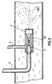
- Sure Figure 5 the venturi is placed in a liquid line 25
- Another application of the device is to use its low pressure capacity which can be greater than 1 bar. Such a device therefore becomes the main element of a pump empty.
Landscapes
- Chemical & Material Sciences (AREA)
- Chemical Kinetics & Catalysis (AREA)
- Nozzles (AREA)
- Casting Or Compression Moulding Of Plastics Or The Like (AREA)
Claims (15)
- Vorrichtung zum Erzeugen von Schaum mit Hilfe des Venturi-Effekts, durch Mischen eines Produktes In flüssiger Phase mit einem Produkt in gasförmiger Phase, mit einer Düse (1) zum Zuführen der Flüssigkeit, koaxial zu einer Venturi-Stufe (22), die einen gegenüberliegend zu der Düse angeordneten konvergenten Teil (18) hat, dessen Engstelle den Durchmesser "D" hat, und einem zu der Düse (1) koaxialen, mit dem konvergenten Teil (18) korrespondierenden Gaseinlaß (3), wobei das Gas durch den Venturi-Effekt angesaugt und in eine Mischkammer (4) eingeleitet wird, die an einen Auslaß für den Schaum angeschlossen ist, dadurch gekennzeichnet. daß der divergente Teil (13) des Venturi-Rohres (22) wenigstens drei Zonen mit progressiven Konizitäten aufweist, mit Bruchlinien zwischen den Zonen, die in Kombination mit der Geometrie des divergenten Teils ein Kavitationsphänomen hervorrufen, und daß der divergente Teil in eine Turbulenzkammer (4) mündet, wobei sich die Durchmischung der beiden Phasen im Freistrahl vollzieht.
- Vorrichtung nach Anspruch 1, dadurch gekennzeichnet, daß der divergente Teil drei Zonen (14, 15, 16) mit zunehmenden Konizitäten aufweist, wobei die erste Zone (14) einen Winkel (α1) zwischen 0 und 10° aufweist.
- Vorrichtung nach den Ansprüchen 1 und 2, dadurch gekennzeichnet, daß die dritte Zone (16) einen Scheitelwinkel (α3) aufweist, der um wenigstens 15° größer ist als der Wert des Winkels (α1) und kleiner als der Wert des Winkels (α1) plus 35°, und eine Länge von weniger als 30D hat.
- Vorrichtung nach den Ansprüchen 1 bis 3, dadurch gekennzeichnet, daß die zweite Zone (15) einen Winkel (α2) aufweist, der um wenigstens 5° größer ist als der durch die erste Zone gebildete Winkel (α1), so daß die Trennlinien der Zonen in Abständen liegen, die zwischen 2D und 4D für die Linie (14, 15) und zwischen 5D und 8D für die Linie (15, 16) in Bezug auf die Linie (X. 14) betragen, die den Auslaß der Engstelle (X) mit der Konizität 0° bildet.
- Vorrichtung nach einem der Ansprüche 1 2 oder 3, dadurch gekennzeichnet. daß der divergente Teil (13) Oberflächendiskontinuitäten wie Riefen oder Raster aufweist.
- Vorrichtung nach einem der Ansprüche 1, 2 oder 3, dadurch gekennzeichnet. daß die Winkel der Konizitätszonen kontinuierlich zunehmen und abgestumpft sind.
- Vorrichtung nach einem der Ansprüche 1 bis 4, dadurch gekennzeichnet, daß der Abstand zwischen dem Auslaß der Düse (1) und dem Einlaß (17) des Venturi-Rohres zwischen 2d und 20d beträgt, wobei (d) der Durchmesser des Kanals der Düse (1) ist und der Durchmesser (2) der Engstelle des Venturi-Rohres zwischen 1.d und 4.d beträgt.
- Vorrichtung nach einem der vorstehenden Ansprüche, dadurch gekennzeichnet, daß die Mischkammer durch eine Einrichtung (21) in der Länge verstellbar ist.
- Vorrichtung nach einem der vorstehenden Ansprüche, dadurch gekennzeichnet, daß die Mischkammer eine Länge von mehr als 30D hat und über eine Leitung (20) in den Auslaß mündet.
- Vorrichtung nach Anspruch 1, dadurch gekennzeichnet, daß zwei Generatoren (10) für Ultraschallwellen radial an der Kammer (4) angeordnet sind.
- Vorrichtung nach einem der vorstehenden Ansprüche, dadurch gekennzeichnet, daß wenigstens ein Mischer und/oder ein Durchsatz- und Druckregler an den Einlaß (9) angeschlossen ist.
- Vorrichtung nach einem der vorstehenden Ansprüche, dadurch gekennzeichnet, daß wenigstens ein Mischer und/oder ein Durchsatz- und Druckregler an den Einlaß (3) angeschlossen ist.
- Vorrichtung nach Anspruch 11, dadurch gekennzeichnet, daß wenigstens ein Mischer an den Einlaß jedes Durchsatz- und Druckreglers angeschlossen ist.
- Vorrichtung nach Anspruch 12, dadurch gekennzeichnet, daß wenigstens ein Durchsatz- und Druckregler an den Einlaß jedes Mischers angeschlossen ist.
- Apparat zur Erzeugung von Schaum, mit einer Vorrichtung nach Anspruch 1, dadurch gekennzeichnet, daß er ein Gehäuse (23) aufweist, das eine Flüssigkeit enthält, in die eine Hülle (26) eintaucht, die aktive Produkte enthält, wobei eine pyrotechnische Einrichtung (24, 25, 27) die Auflösung der aktiven Produkte in der Flüssigkeit bewirkt.
Applications Claiming Priority (7)
| Application Number | Priority Date | Filing Date | Title |
|---|---|---|---|
| FR9608162A FR2750347A1 (fr) | 1996-07-01 | 1996-07-01 | Procede de production de mousse optimise et reglable, ainsi que l'appareil concu a cet effet |
| FR9608162 | 1996-07-01 | ||
| FR9610947 | 1996-09-09 | ||
| FR9610947 | 1996-09-09 | ||
| FR9700690 | 1997-01-23 | ||
| FR9700690A FR2758476A1 (fr) | 1997-01-23 | 1997-01-23 | Appareil de production de mousse optimise et reglable |
| PCT/FR1997/001167 WO1998000227A1 (fr) | 1996-07-01 | 1997-07-01 | Dispositif de generation de mousse |
Publications (2)
| Publication Number | Publication Date |
|---|---|
| EP0869841A1 EP0869841A1 (de) | 1998-10-14 |
| EP0869841B1 true EP0869841B1 (de) | 2003-06-04 |
Family
ID=27253196
Family Applications (1)
| Application Number | Title | Priority Date | Filing Date |
|---|---|---|---|
| EP97931836A Expired - Lifetime EP0869841B1 (de) | 1996-07-01 | 1997-07-01 | Schaumstoffherstellungsvorrichtung |
Country Status (6)
| Country | Link |
|---|---|
| US (1) | US6042089A (de) |
| EP (1) | EP0869841B1 (de) |
| AT (1) | ATE242044T1 (de) |
| CA (1) | CA2231338A1 (de) |
| DE (1) | DE69722583D1 (de) |
| WO (1) | WO1998000227A1 (de) |
Families Citing this family (47)
| Publication number | Priority date | Publication date | Assignee | Title |
|---|---|---|---|---|
| US6561438B1 (en) * | 1997-07-15 | 2003-05-13 | The Fountainhead Group | Foam generating nozzle assembly |
| US6669902B1 (en) * | 2000-11-08 | 2003-12-30 | L'air Liquide - Societe Anonyme A'directoire Et Conseil De Surveillance Pour L'etude Et L'exploitation Des Procedes Georges Claude | Ozonated foam medium and production system and method for sanitizing a food processing environment |
| RU2184619C1 (ru) * | 2001-03-22 | 2002-07-10 | Душкин Андрей Леонидович | Распылитель жидкости (варианты) |
| US8512680B2 (en) * | 2001-08-08 | 2013-08-20 | Btg International Ltd. | Injectables in foam, new pharmaceutical applications |
| DE10228853B4 (de) * | 2002-06-27 | 2007-02-08 | Esau & Hueber Gmbh | Düsenanordnung zum Einleiten von Gas in eine Flüssigkeit |
| US6986506B2 (en) * | 2003-05-01 | 2006-01-17 | Chapman Teddie C | Water aerator and method of using same |
| US7156377B2 (en) * | 2003-05-01 | 2007-01-02 | Chapman Teddie C | Water aeration device and method |
| JP5292046B2 (ja) | 2007-10-26 | 2013-09-18 | ローム アンド ハース カンパニー | 建造物用の耐候性バリア |
| EP2053082B1 (de) | 2007-10-26 | 2019-07-10 | Rohm and Haas Company | Wetterbeständige Gebäudeabdichtung |
| JP4760843B2 (ja) * | 2008-03-13 | 2011-08-31 | 株式会社デンソー | エジェクタ装置およびエジェクタ装置を用いた蒸気圧縮式冷凍サイクル |
| CN101371944B (zh) * | 2008-08-22 | 2012-01-11 | 杭州新纪元安全产品有限公司 | 用洁净气体作为发泡剂的灭火产品及制作方法和灭火系统 |
| US8286836B2 (en) * | 2008-10-14 | 2012-10-16 | Gojo Industries, Inc. | Dispensing tube assembly and foam generator for coaxial tubes |
| US8360339B2 (en) * | 2008-11-13 | 2013-01-29 | Forced Gas Technologies, Llc | Fire suppression apparatus and method for generating foam |
| EP2210925B1 (de) | 2009-01-21 | 2020-05-06 | Rohm and Haas Company | Vorrichtung zum leichten Auftragen von Dichtmittel |
| US8763617B2 (en) | 2009-06-24 | 2014-07-01 | Saint-Gobain Abrasives, Inc. | Material removal systems and methods utilizing foam |
| JP5876472B2 (ja) | 2010-04-14 | 2016-03-02 | ダウ グローバル テクノロジーズ エルエルシー | フロス及び非フロスコーティング用の分配装置 |
| US20110284648A1 (en) * | 2010-04-20 | 2011-11-24 | California Institute Of Technology | Method to generate micro scale gas filled liquid bubbles as tracer particles or inhaler mist for drug delivery |
| US8104745B1 (en) * | 2010-11-20 | 2012-01-31 | Vladimir Vladimirovich Fisenko | Heat-generating jet injection |
| CN102247673B (zh) * | 2011-07-05 | 2013-02-13 | 淄博吉孚消防科技有限公司 | 压缩气体泡沫灭火系统气液比例混合发泡器 |
| KR101351301B1 (ko) * | 2012-10-23 | 2014-01-15 | 주식회사 디섹 | 선박의 밸러스트수 처리시스템 |
| WO2014151243A1 (en) * | 2013-03-15 | 2014-09-25 | Fluid-Quip, Inc. | Pulse cavitation processor and method of using same |
| AT514381B1 (de) * | 2013-04-04 | 2015-05-15 | Avl List Gmbh | Venturiverdünner |
| BR112016007366B1 (pt) | 2013-10-02 | 2021-05-18 | Aerocore Technologies Llc | método de limpeza para motor de turbina a gás |
| US11643946B2 (en) | 2013-10-02 | 2023-05-09 | Aerocore Technologies Llc | Cleaning method for jet engine |
| US10441926B2 (en) * | 2013-10-17 | 2019-10-15 | Ashok Adrian Singh | Fluid treatment apparatus and process |
| DE102013225612B4 (de) | 2013-12-11 | 2017-12-14 | Lechler Gmbh | Injektordüse |
| CN103752204B (zh) * | 2014-01-26 | 2016-02-03 | 中国地质大学(武汉) | 一种用于多成分冲洗液的分散处理装置 |
| US10857100B2 (en) | 2014-04-01 | 2020-12-08 | Tdl Innovations Llc | Methods and compositions for administering an active agent to the pleura of a patient |
| EP3125944A4 (de) | 2014-04-01 | 2017-11-22 | TDL Innovations, LLC | Verfahren und zusammensetzungen zur verabreichung eines wirkstoffs auf die pleura eines patienten |
| US10233097B2 (en) | 2014-12-08 | 2019-03-19 | Fluid-Quip, Inc. | Liquid treatment apparatus with ring vortex processor and method of using same |
| AU2015261669A1 (en) * | 2014-12-08 | 2016-06-23 | Robert Pulz | A Firefighting Foam Generator |
| US11691041B1 (en) | 2015-07-17 | 2023-07-04 | Gregory A. Blanchat | Compressed air foam mixing device |
| US10099078B1 (en) | 2015-07-17 | 2018-10-16 | Gregory A. Blanchat | Compressed air foam mixing device |
| CN105909567B (zh) * | 2016-06-15 | 2018-08-21 | 江苏大学 | 一种改善射流式离心泵空化性能的射流器 |
| US11077411B2 (en) | 2016-07-25 | 2021-08-03 | Shibata Corporation | Bubble generating device |
| US12064510B2 (en) * | 2016-12-16 | 2024-08-20 | TDL Innovations, LLC | Medical foam for delivery of an active agent |
| US11229502B1 (en) | 2017-06-03 | 2022-01-25 | Knight, Llc | Instrument cleaning systems and methods |
| JP6961219B2 (ja) * | 2017-09-21 | 2021-11-05 | ミクニ総業株式会社 | マイクロ・ナノバブル発生器及び配管洗浄方法 |
| WO2020005640A1 (en) | 2018-06-29 | 2020-01-02 | Corning Research & Development Corporation | Spray nozzle, systems, and methods for cleaning optical fiber connectors |
| PT110818A (pt) * | 2018-07-04 | 2020-01-06 | Nanospectral Lda | Processo de cavitação para preparação de emulsões de combustível com água e reactor para a realização do processo. |
| CN109731490A (zh) * | 2018-08-21 | 2019-05-10 | 北京环域生态环保技术有限公司 | 一种二次加压多级破碎的纳米气泡发生方法及装置 |
| CN110036996A (zh) * | 2019-04-13 | 2019-07-23 | 安徽瓦尔特机械贸易有限公司 | 一种植保无人机用烟雾机 |
| CN112439574B (zh) * | 2019-09-05 | 2025-02-21 | 青岛海尔洗衣机有限公司 | 气液混合管结构以及具有该气液混合管结构的洗涤设备 |
| DE102019213569A1 (de) | 2019-09-06 | 2021-03-11 | Lechler Gmbh | Injektionsdüse für eine Sprühvorrichtung und Sprühvorrichtung |
| CN111779099B (zh) | 2020-06-05 | 2026-01-16 | 厦门科牧智能技术有限公司 | 一种发泡喷射装置及发泡装置和发泡马桶 |
| IT202000016327A1 (it) * | 2020-07-06 | 2022-01-06 | Omitaly Srl | Dispositivo generatore di micro e nano bolle |
| CN115501994B (zh) * | 2022-10-11 | 2023-08-22 | 山东科川节能环保科技有限公司 | 一种旋流高效、防倒流喷射的喷射装置 |
Family Cites Families (18)
| Publication number | Priority date | Publication date | Assignee | Title |
|---|---|---|---|---|
| DE1249223B (de) * | 1967-09-07 | C. A. Norgren Co., Englewood, Col. (V. St. A.) | Aerosol-Erzeuger | |
| BE517287A (de) * | 1952-02-05 | |||
| US3838002A (en) * | 1972-07-21 | 1974-09-24 | Gen Electric | Jet pump for nuclear reactor |
| US4098851A (en) * | 1974-02-20 | 1978-07-04 | Erdolchemie Gesellschaft Mit Beschrankter Haftung | Device for mixing gases and liquids |
| NO760028L (de) * | 1975-02-24 | 1976-08-25 | Dresser Ind | |
| US4333833A (en) * | 1978-05-08 | 1982-06-08 | Fischer & Porter Co. | In-line disinfectant contactor |
| US4308138A (en) * | 1978-07-10 | 1981-12-29 | Woltman Robert B | Treating means for bodies of water |
| GB2026093A (en) * | 1978-07-12 | 1980-01-30 | Dresser Ind | Jet pump nozzle construction |
| US4802630A (en) * | 1985-11-19 | 1989-02-07 | Ecolab Inc. | Aspirating foamer |
| GB8610636D0 (en) * | 1986-04-30 | 1986-06-04 | Pringle J M | Induced flow mixers |
| US4861165A (en) * | 1986-08-20 | 1989-08-29 | Beloit Corporation | Method of and means for hydrodynamic mixing |
| GB2203065A (en) * | 1987-04-11 | 1988-10-12 | Wormald Ansul | Foam dispensing nozzle |
| US5054688A (en) * | 1989-12-20 | 1991-10-08 | Robwen, Inc. | Foam producing nozzle |
| US5085371A (en) * | 1990-06-15 | 1992-02-04 | Shop-Vac Corporation | Foam creating nozzle system |
| US5061406A (en) * | 1990-09-25 | 1991-10-29 | Union Carbide Industrial Gases Technology Corporation | In-line gas/liquid dispersion |
| US5275763A (en) * | 1992-10-26 | 1994-01-04 | Toshiharu Fukai | Nozzle for generating bubbles |
| US5431346A (en) * | 1993-07-20 | 1995-07-11 | Sinaisky; Nickoli | Nozzle including a venturi tube creating external cavitation collapse for atomization |
| US5423488A (en) * | 1994-05-11 | 1995-06-13 | Davidson Textron Inc. | Spray apparatus for mixing, atomizing and spraying foam forming components |
-
1997
- 1997-07-01 US US09/029,417 patent/US6042089A/en not_active Expired - Fee Related
- 1997-07-01 EP EP97931836A patent/EP0869841B1/de not_active Expired - Lifetime
- 1997-07-01 CA CA002231338A patent/CA2231338A1/fr not_active Abandoned
- 1997-07-01 DE DE69722583T patent/DE69722583D1/de not_active Expired - Lifetime
- 1997-07-01 AT AT97931836T patent/ATE242044T1/de not_active IP Right Cessation
- 1997-07-01 WO PCT/FR1997/001167 patent/WO1998000227A1/fr not_active Ceased
Also Published As
| Publication number | Publication date |
|---|---|
| DE69722583D1 (de) | 2003-07-10 |
| ATE242044T1 (de) | 2003-06-15 |
| EP0869841A1 (de) | 1998-10-14 |
| WO1998000227A1 (fr) | 1998-01-08 |
| US6042089A (en) | 2000-03-28 |
| CA2231338A1 (fr) | 1998-01-08 |
Similar Documents
| Publication | Publication Date | Title |
|---|---|---|
| EP0869841A1 (de) | Schaumstoffherstellungsvorrichtung | |
| CA1269410A (en) | Aspirating foamer | |
| KR101244237B1 (ko) | 고속의 저압 배출기 | |
| CN102271766A (zh) | 用于产生泡沫的灭火设备和方法 | |
| Lin et al. | Structures of internal flow and the corresponding spray for aerated-liquid injectors | |
| WO2010052388A1 (fr) | Procede de formation d'une emulsion a partir de liquides non miscibles en eux et application a l'alimentation en liquide d'un dispositif de nebulisation | |
| FR2750347A1 (fr) | Procede de production de mousse optimise et reglable, ainsi que l'appareil concu a cet effet | |
| FR2758476A1 (fr) | Appareil de production de mousse optimise et reglable | |
| JP2011025202A (ja) | 機能ミスト生成装置 | |
| WO2002043847A1 (fr) | Procede, module et dispositif de mise en contact d'un gaz et d'un liquide | |
| JP2011025203A (ja) | 機能ミスト生成装置 | |
| US20030164465A1 (en) | Method and apparatus for producing foam | |
| EP1899021A1 (de) | Feuerlöscher aus flüssignebel und verwendung dafür | |
| EP3840847A1 (de) | Niederdruck-nebel-feuerlöscheinrichtung und bauteilsatz für eine niederdruck-nebel-feuerlöscheinrichtung | |
| EP0122846B1 (de) | Flüssigprodukt mit hohem Energieinhalt und dessen Verwendung bei der Speisung eines Reaktionsraumes mit brennbarem Material | |
| EP3113867B1 (de) | Verfahren und vorrichtung zur dispersion von gas in einer flüssigkeit | |
| MXPA04010449A (es) | Dispositivo y metodo para crear gravitacion hidrodinamica en fluidos. | |
| KR20120084134A (ko) | 마이크로 버블 헤드 및 이를 구비하는 마이크로 버블 생성장치 | |
| EP1202795B1 (de) | Verfahren und vorrichtungen zur herstellung von emulsionen | |
| RU2258568C1 (ru) | Распылитель жидкости | |
| JP2008178779A (ja) | 微細気泡発生装置 | |
| US20070158467A1 (en) | Foam generator | |
| JP2000254483A (ja) | キャビテーション反応装置 | |
| FR3159915A1 (fr) | Dispositif de nettoyage projetant un jet formé à partir d’un liquide et d’un gaz sous pression | |
| JP4364876B2 (ja) | 気体溶解装置 |
Legal Events
| Date | Code | Title | Description |
|---|---|---|---|
| PUAI | Public reference made under article 153(3) epc to a published international application that has entered the european phase |
Free format text: ORIGINAL CODE: 0009012 |
|
| 17P | Request for examination filed |
Effective date: 19980320 |
|
| AK | Designated contracting states |
Kind code of ref document: A1 Designated state(s): AT BE CH DE ES FR GB IT LI SE |
|
| RAP1 | Party data changed (applicant data changed or rights of an application transferred) |
Owner name: HEURTAUX S.A.S. |
|
| RIN1 | Information on inventor provided before grant (corrected) |
Inventor name: HEURTAUX S.A.S. |
|
| GRAG | Despatch of communication of intention to grant |
Free format text: ORIGINAL CODE: EPIDOS AGRA |
|
| 17Q | First examination report despatched |
Effective date: 20020619 |
|
| GRAG | Despatch of communication of intention to grant |
Free format text: ORIGINAL CODE: EPIDOS AGRA |
|
| GRAH | Despatch of communication of intention to grant a patent |
Free format text: ORIGINAL CODE: EPIDOS IGRA |
|
| GRAH | Despatch of communication of intention to grant a patent |
Free format text: ORIGINAL CODE: EPIDOS IGRA |
|
| GRAA | (expected) grant |
Free format text: ORIGINAL CODE: 0009210 |
|
| AK | Designated contracting states |
Designated state(s): AT BE CH DE ES FR GB IT LI SE |
|
| PG25 | Lapsed in a contracting state [announced via postgrant information from national office to epo] |
Ref country code: IT Free format text: LAPSE BECAUSE OF FAILURE TO SUBMIT A TRANSLATION OF THE DESCRIPTION OR TO PAY THE FEE WITHIN THE PRESCRIBED TIME-LIMIT;WARNING: LAPSES OF ITALIAN PATENTS WITH EFFECTIVE DATE BEFORE 2007 MAY HAVE OCCURRED AT ANY TIME BEFORE 2007. THE CORRECT EFFECTIVE DATE MAY BE DIFFERENT FROM THE ONE RECORDED. Effective date: 20030604 Ref country code: GB Free format text: LAPSE BECAUSE OF FAILURE TO SUBMIT A TRANSLATION OF THE DESCRIPTION OR TO PAY THE FEE WITHIN THE PRESCRIBED TIME-LIMIT Effective date: 20030604 Ref country code: AT Free format text: LAPSE BECAUSE OF FAILURE TO SUBMIT A TRANSLATION OF THE DESCRIPTION OR TO PAY THE FEE WITHIN THE PRESCRIBED TIME-LIMIT Effective date: 20030604 |
|
| REG | Reference to a national code |
Ref country code: GB Ref legal event code: FG4D Free format text: NOT ENGLISH |
|
| RIN1 | Information on inventor provided before grant (corrected) |
Inventor name: KLEIN, CHRISTOPHE |
|
| REG | Reference to a national code |
Ref country code: CH Ref legal event code: EP |
|
| REF | Corresponds to: |
Ref document number: 69722583 Country of ref document: DE Date of ref document: 20030710 Kind code of ref document: P |
|
| PG25 | Lapsed in a contracting state [announced via postgrant information from national office to epo] |
Ref country code: LI Free format text: LAPSE BECAUSE OF NON-PAYMENT OF DUE FEES Effective date: 20030731 Ref country code: CH Free format text: LAPSE BECAUSE OF NON-PAYMENT OF DUE FEES Effective date: 20030731 Ref country code: BE Free format text: LAPSE BECAUSE OF NON-PAYMENT OF DUE FEES Effective date: 20030731 |
|
| PG25 | Lapsed in a contracting state [announced via postgrant information from national office to epo] |
Ref country code: SE Free format text: LAPSE BECAUSE OF FAILURE TO SUBMIT A TRANSLATION OF THE DESCRIPTION OR TO PAY THE FEE WITHIN THE PRESCRIBED TIME-LIMIT Effective date: 20030904 |
|
| PG25 | Lapsed in a contracting state [announced via postgrant information from national office to epo] |
Ref country code: DE Free format text: LAPSE BECAUSE OF FAILURE TO SUBMIT A TRANSLATION OF THE DESCRIPTION OR TO PAY THE FEE WITHIN THE PRESCRIBED TIME-LIMIT Effective date: 20030905 |
|
| PG25 | Lapsed in a contracting state [announced via postgrant information from national office to epo] |
Ref country code: ES Free format text: LAPSE BECAUSE OF FAILURE TO SUBMIT A TRANSLATION OF THE DESCRIPTION OR TO PAY THE FEE WITHIN THE PRESCRIBED TIME-LIMIT Effective date: 20030915 |
|
| GBV | Gb: ep patent (uk) treated as always having been void in accordance with gb section 77(7)/1977 [no translation filed] |
Effective date: 20030604 |
|
| BERE | Be: lapsed |
Owner name: *HEURTAUX S.A.S. Effective date: 20030731 |
|
| REG | Reference to a national code |
Ref country code: CH Ref legal event code: PL |
|
| PLBE | No opposition filed within time limit |
Free format text: ORIGINAL CODE: 0009261 |
|
| STAA | Information on the status of an ep patent application or granted ep patent |
Free format text: STATUS: NO OPPOSITION FILED WITHIN TIME LIMIT |
|
| 26N | No opposition filed |
Effective date: 20040305 |
|
| REG | Reference to a national code |
Ref country code: FR Ref legal event code: PLFP Year of fee payment: 20 |
|
| PGFP | Annual fee paid to national office [announced via postgrant information from national office to epo] |
Ref country code: FR Payment date: 20160523 Year of fee payment: 20 |