EP0870083B1 - Pompage de pulpes de consistance moyenne et de temperature elevee a partir de colonnes d'alimentation - Google Patents
Pompage de pulpes de consistance moyenne et de temperature elevee a partir de colonnes d'alimentation Download PDFInfo
- Publication number
- EP0870083B1 EP0870083B1 EP96943144A EP96943144A EP0870083B1 EP 0870083 B1 EP0870083 B1 EP 0870083B1 EP 96943144 A EP96943144 A EP 96943144A EP 96943144 A EP96943144 A EP 96943144A EP 0870083 B1 EP0870083 B1 EP 0870083B1
- Authority
- EP
- European Patent Office
- Prior art keywords
- pulp
- stand pipe
- pump
- gas
- pressurizing
- Prior art date
- Legal status (The legal status is an assumption and is not a legal conclusion. Google has not performed a legal analysis and makes no representation as to the accuracy of the status listed.)
- Revoked
Links
- 238000005086 pumping Methods 0.000 title claims description 22
- 238000000034 method Methods 0.000 claims description 25
- 239000001913 cellulose Substances 0.000 claims description 19
- 229920002678 cellulose Polymers 0.000 claims description 19
- 238000007599 discharging Methods 0.000 claims description 10
- 239000012528 membrane Substances 0.000 claims description 8
- 230000015572 biosynthetic process Effects 0.000 claims description 7
- 239000002562 thickening agent Substances 0.000 claims description 6
- 238000006073 displacement reaction Methods 0.000 claims description 3
- 239000012530 fluid Substances 0.000 claims description 3
- 230000005484 gravity Effects 0.000 claims description 3
- 238000004061 bleaching Methods 0.000 description 6
- 238000010790 dilution Methods 0.000 description 6
- 239000012895 dilution Substances 0.000 description 6
- CBENFWSGALASAD-UHFFFAOYSA-N Ozone Chemical compound [O-][O+]=O CBENFWSGALASAD-UHFFFAOYSA-N 0.000 description 5
- 238000009835 boiling Methods 0.000 description 4
- 238000007872 degassing Methods 0.000 description 4
- 230000014759 maintenance of location Effects 0.000 description 4
- 230000001105 regulatory effect Effects 0.000 description 4
- 239000000243 solution Substances 0.000 description 4
- 238000006243 chemical reaction Methods 0.000 description 3
- 238000010276 construction Methods 0.000 description 3
- 239000000835 fiber Substances 0.000 description 3
- 239000007788 liquid Substances 0.000 description 3
- 238000000926 separation method Methods 0.000 description 3
- XLYOFNOQVPJJNP-UHFFFAOYSA-N water Substances O XLYOFNOQVPJJNP-UHFFFAOYSA-N 0.000 description 3
- 230000001276 controlling effect Effects 0.000 description 2
- 210000004262 dental pulp cavity Anatomy 0.000 description 2
- 239000000463 material Substances 0.000 description 2
- 238000003860 storage Methods 0.000 description 2
- 238000011144 upstream manufacturing Methods 0.000 description 2
- BDAGIHXWWSANSR-UHFFFAOYSA-M Formate Chemical compound [O-]C=O BDAGIHXWWSANSR-UHFFFAOYSA-M 0.000 description 1
- 230000002411 adverse Effects 0.000 description 1
- 238000007664 blowing Methods 0.000 description 1
- 238000004891 communication Methods 0.000 description 1
- 230000000694 effects Effects 0.000 description 1
- 239000002655 kraft paper Substances 0.000 description 1
- 238000004519 manufacturing process Methods 0.000 description 1
- 238000012986 modification Methods 0.000 description 1
- 230000004048 modification Effects 0.000 description 1
- 239000002245 particle Substances 0.000 description 1
- 238000004537 pulping Methods 0.000 description 1
- 239000000725 suspension Substances 0.000 description 1
Images


Classifications
-
- D—TEXTILES; PAPER
- D21—PAPER-MAKING; PRODUCTION OF CELLULOSE
- D21C—PRODUCTION OF CELLULOSE BY REMOVING NON-CELLULOSE SUBSTANCES FROM CELLULOSE-CONTAINING MATERIALS; REGENERATION OF PULPING LIQUORS; APPARATUS THEREFOR
- D21C7/00—Digesters
- D21C7/14—Means for circulating the lye
-
- D—TEXTILES; PAPER
- D21—PAPER-MAKING; PRODUCTION OF CELLULOSE
- D21C—PRODUCTION OF CELLULOSE BY REMOVING NON-CELLULOSE SUBSTANCES FROM CELLULOSE-CONTAINING MATERIALS; REGENERATION OF PULPING LIQUORS; APPARATUS THEREFOR
- D21C7/00—Digesters
- D21C7/08—Discharge devices
Definitions
- the present invention relates to pumping of medium consistency cellulose pulp.
- the invention is especially concerned with pumping of pulps from stand pipes or like small sized pulp vessels to which pulp is normally discharged from storage towers, treatment towers, washers, filters, presses, thickeners etc. More specifically the invention relates to the pumping of high temperature pulps from the stand pipes.
- a centrifugal pump no matter whether it is an ordinary centrifugal pump or a fluidizing centrifugal pump (MC® pump) capable of pumping medium consistency pulps, tends to create a certain suction head at its inlet. This reduced pressure lowers the boiling point of the liquid present in the pulp.
- These pumps are provided with a gas flow channel, normally leading through the impeller to the backside of the impeller and then to the vacuum pump (disposed either on the same shaft as the centrifugal impeller or on a shaft separate from the centrifugal pump) , and from there to the atmosphere or to some other location, for instance, to a gas collection system.
- a stand pipe is a relatively small size vessel which receives pulp from a washer, thickener, bleaching tower, or storage tower in a conventional pulp mill (typically a kraft pulp mill). While the term "stand pipe” is used in the present specification and claims it is to be understood that this term encompasses similar small vessels which may not be technically known as a "stand pipe” in the pulping art.
- the required pressure difference is the sum of the subatmospheric pressure created by the vacuum pump and the net positive suction head i.e. the inlet pressure.
- the maximum value of the subatmospheric pressure is dictated by the temperature of the pulp in the pump inlet. If the temperature is for instance close to 100°C with a low inlet height there cannot, in practice, be any suction created by the vacuum pump so that the gas or steam is discharged merely as a result of the inlet pressure. This also ensues even if the inlet height as such is high but the pulp is of particularly high consistency so that the surface friction lowers the effective pressure to a very low value.
- the net positive suction head is often impossible due to the constructional limitations at the pulp mill e.g. if a washer is disposed on the first floor of the pulp mill it is impractical to position the stand pipe and the pump in a deep hole below the ground floor. Also with higher consistencies it becomes impossible, or senseless, to increase the height of the stand pipe as the surface friction between the pulp and the stand pipe wall in any case lowers the true effective pressure at the bottom of the stand pipe. The pulp "hangs" on the wall of the stand pipe and does not flow easily downwardly. A solution to this problem would be to increase the conicity of the stand pipe i.e. make the stand pipe widen more rapidly downwardly. However, this would lead to an impossible structure as the diameter of the bottom of the stand pipe would grow so wide that a substantial portion of pulp would remain standing on the pipe bottom resulting in arching problems in front of the discharge outlet of the stand pipe.
- the problem with the decrease of the pumping ability is solved by pressurizing the inlet opening of the pump in a totally different manner. This is done by pressuring a stand pipe to which the pump inlet is connected.
- the problem relating to the weak flow of pulp down into the stand pipe has also been solved in a novel and inventive way.
- the solution offers the opportunity to use, in practice, unlimited temperature in the stand pipe so that it becomes possible to operate, for instance, a sequence of bleaching towers and intermediate pressurized washers, thickeners and filters, continuously at a temperature exceeding 100°C.
- a disc filter which has been pressurized by means of blowing air through the shaft of the disc filter into the filter sectors so that the thickened pulp cake is removed by pressurized air. Simultaneously with the discharge of the cake the air pressurizes the interior of the disc filter as well as the discharge chute of the filter.
- the discharge chute is provided with a longitudinal feed screw for feeding pulp to an end of the apparatus where the pulp enters at substantially the same vertical level another feed chute where another screw feeds the pulp into a thick stock pump which is a positive displacement type pump.
- the thick stock pump is the final pressure lock which ensures that the pressure is at a predetermined level within the disc filter.
- US-A-3,096,234 discusses a continuous digesting system where pulp is discharged from a digester at a consistency of about 4.5 % to a liquid transfer press where the consistency is raised up to 20 to 40 percents. The pulp is discharged from the press (substantially at digesting temperature) to a dilution tank where the consistency is adjusted between 2 and 10 percents with liquor having a substantially lower temperature. The pulp is further pumped from the dilution tank further by means of a pump.
- the dilution tank is pressurized.
- the purpose for the pressurization of the dilution tank is described to be for controlling the flow of pulp into the tank and for maintaining proper pressure within the digester.
- the bleached pulp is discharged from the retention vessel from the bottom thereof by means of a degassing fluidizing pump.
- Both the reaction vessel and the retention vessel are pressurized but such has been done merely for compressing the ozone containing gas to make ozone bleaching possible.
- D2 does not recognize the problems relating to pumping
- the above described problems have been solved by the novel method of pumping cellulose pulp having a consistency of between about 8 - 18% according to the invention.
- the method comprises the steps of: (a) Attaching the pump inlet to the discharge opening of a stand pipe. (b) Pressuring cellulose pulp having a consistency of between about 8-18% in the stand pipe by closing off the stand pipe from atmosphere. (c) Maintaining a superatmospheric pressure in the stand pipe. (d) Causing the cellulose pulp to flow into the pump through the pump inlet. And, (e) pumping the cellulose pulp away from the stand pipe using the pump.
- Another preferred feature of the method is the formation of a gas space above the pulp by pressurizing, utilizing a pressurizing gas, the stand pipe to thereby force the pulp into the pump inlet under the influence of both gravity and fluid pressure.
- the apparatus for practising the above method comprises a stand pipe having a top portion and a bottom portion, a pulp pump having an inlet, the inlet to the pulp pump being connected to the bottom portion of the stand pipe so that pulp may flow from the bottom portion of the stand pipe to the pump inlet.
- the stand pipe is preferably closed off from the atmosphere and has a gas space at the top portion thereof.
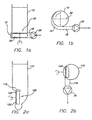
- FIGURES 1a through 4 there are illustrated different feeder devices which may be used for assisting the discharge of medium consistency pulp from a stand pipe.
- FIGURES 1a and 1b show a first exemplary apparatus for discharging pulp from a stand pipe.
- the bottom of the stand pipe 10 is provided with a rotor 20 which acts like a centrifugal pump feeding pulp towards the outlet opening and the pump 30 (e.g. an MC® pump such as sold by Ahlstrom Pumps Corporation) attached thereto.
- the rotor 20 may have either straight or curved vanes 22. If the vanes 22 are straight they may be either radial or inclined.
- the bottom area 12 of the stand pipe 10 surrounding the rotor 20 may be circular with a tangential outlet 18 or it may preferably be formed like a spiral housing 14 of a centrifugal pump.
- the axis of the rotor 20 may be vertical, as shown in FIGURE 1a, but it may alternatively be inclined if the bottom of the stand pipe 10 is not horizontal.
- the stand pipe 10 preferably has a cross-sectional area that increases from the top towards the bottom so that the pulp flows easily downwards due to gravity. However, especially at lower consistencies, the walls of the stand pipe 10 alternatively may be parallel, preferably horizontal, or inclined, or vertical.
- FIGURES 2a and 2b show a second exemplary apparatus for discharging pulp from a stand pipe.
- a rotor 120 positioned to rotate in a vertical plane about a horizontal axis.
- the rotor 120 is surrounded by either a substantially cylindrical volute or a spiral volute 116 having a tangential outlet 118 to which a conventional pump 30 (e.g. an MC® pump) is further attached.
- a conventional pump 30 e.g. an MC® pump
- the bottom portion of the stand pipe 110 is provided with a planar wall portion 102 through which the drive of the rotor is disposed.
- the drawings illustrate a horizontal axis for the rotor, the axis also can be inclined.
- FIGURES 3a and 3b show a third exemplary apparatus for discharging pulp from a stand pipe.
- the horizontal shaft 224 of the rotor 220 is, preferably, extended across the stand pipe 210 so that it is supported by bearings both at its drive (D) end and its free end.
- the rotor 220 is disposed substantially centrally in the stand pipe 210 bottom area. Since the rotor 220 is of a double suction type, the rotor 220 preferably has a central plate 226 on both faces, to which curved or straight vanes 222 are attached.
- the rotor 220 is surrounded by either a cylindrical or, preferably, a spiral housing 216 having a tangential outlet 218 attached to the conventional pump 30.
- FIGURE 4 illustrates a fourth exemplary apparatus for discharging medium consistency pulp from a stand pipe.
- a propeller 28 feeding pulp towards the pump 30 discharging pulp from the stand pipe 400.
- the rotational speed of the propeller 28 is higher than that of the impeller of the pump 30, preferably by at least 5%, more preferably by at least 10%.
- the propeller could be replaced with a feeder screw, or a set of feeder blades or vanes attached either on the same shaft with the centrifugal impeller or on a separate shaft driven by another drive (e.g. motor).
- FIGURE 5 illustrates a first preferred embodiment of the present invention.
- the stand pipe 500 is provided with an upright pressurized housing having at its upper end a pressure cover 404.
- the pressure cover is provided with a pocket feeder 506 (the elements 504, 506 collectively comprising one example of a means for allowing the stand pipe 500 to be maintained at superatmospheric pressure).
- the pocket feeder 506 could be replaced with an arrangement having two valves, gates or ports arranged in series and having a pulp chamber in between the valves, ports or gates being operated in such a manner that while the "lower” valve is closed the “upper” one is open allowing the chamber to fill and then after closing of the "upper” valve the "lower” one is opened so that the pulp chamber could be emptied, or a piston feeder, or a suitable positive displacement pump, or some other appropriate means for transporting pulp from a lower pressure to a higher pressure. It should however be understood that the transporting means does not necessarily have to be positioned at the pressure cover but it may alternatively be located at the substantially vertical wall of the pressure housing, for instance.
- the pressure housing i.e. the stand pipe 500
- the pressure housing is preferably substantially cylindrical and/or slightly downwardly widening.
- the stand pipe 500 is provided with an outlet opening 502 and with a centrifugal pump 30 disposed in communication with the outlet opening 502.
- the centrifugal pump 30 is preferably a fluidizing centrifugal pump i.e. an MC® pump.
- the stand pipe 500 is further provided with means 508 for pressurizing the interior cavity of the stand pipe 500 i.e to form therein a gas space 510.
- the pressurizing means 508 is, for instance, a vacuum pump sucking (e.g.
- the degassing vacuum pump is a very cheap and convenient way of pressurization of the stand pipe.
- the discharge of the degassing vacuum pump is directed into the stand pipe as in some cases some fibers may be drawn into the degasifying system so that the fibers are returned into the stand pipe and back to use.
- Pressurization may alternatively be effected by a totally independent pump means, for example a compressor or a blower for pumping outside air, some other gas, or steam, into the stand pipe 500.
- the pressurization of the stand pipe may be effected from the pulp mill's pressurized air pipelines without any separate devices to effect pressurization.
- FIGURES 6a and 6b illustrate another preferred embodiments of the present invention.
- the stand pipe of FIGURES 6a and 6b is composed of a vertically oriented, preferably, due to ease of manufacture, substantially cylindrical pressure housing 600 and at its upper end a pressure cover 604.
- the bottom end of the stand pipe 600 is provided with an outlet opening 602 for the discharge of the fiber suspension using a centrifugal pump 30 which may be either a fluidizing centrifugal pump i.e. a MC® pump or an ordinary, non-fluidizing, centrifugal pump.
- the bottom end of the stand pipe of FIGURE 6a is also provided with an inlet opening 605 for receiving pulp from a preceding process step.
- the wall of the stand pipe 600 of FIGURE 6b is provided close to the pulp surface S, preferably therebelow, with an inlet opening 605' for receiving pulp from a preceding process step.
- the inlet opening 605 and 605' is provided with an inlet pipe 609 converging towards the inlet opening 605 and 605' .
- a feed means 606, in this embodiment a feed screw is arranged to extend from outside the stand pipe 600 into the inlet pipe 609 to feed pulp in a steady flow through the inlet pipe 609 and inlet opening 605 and 605' into the stand pipe 600.
- the pulp forms a plug which allows the stand pipe 600 to be at a superatmospheric pressure.
- the first alternative is equal to the one discussed in connection with FIGURE 5, i.e. the use of a compressor or some other means at the upper end of the stand pipe 600 for pressurizing the stand pipe 600.
- Another alterative is, while starting the process, to start filling the stand pipe 600 without yet starting the centrifugal pump 30. In other words, the stand pipe 600 is filled up to certain level S to form a gas space 610 and to reach a desired pressure at the top end of the stand pipe 600 whereafter the centrifugal pump 30 is started.
- the process would, then, be run in such a manner that the pulp level S in the stand pipe 600 is maintained at the desired height dictated by the pressure at the top end of the stand pipe 600.
- the pump capacity may be adjusted by means of a valve 612 regulating the outlet flow from the pump 30 as a function of the pulp level S or by means of a valve 612' regulating the outlet flow from the pump 30 as a function of the pressure in the gas space 610. It is also possible to arrange a compressor 608 (shown in FIGURE 6a) or some other means for pressurizing the stand pipe 600 if deemed necessary.
- the best way to control the operation of the stand pipe is to separately monitor the pressure within the gas space and the pulp level in the stand pipe 600.
- the compressor 608 or blower is regulated to provide a constant pressure in the gas space
- the outlet flow of the centrifugal pump is regulated to maintain the pulp level S in the stand pipe at an optimal value, or between certain, upper and lower, limits.
- valve 612' may be used with the inlet opening 605 positioned at the bottom of the stand pipe 600 as well as valve 612 in connection with an inlet opening 605' positioned higher at the wall of the stand pipe 600.
- FIGURES 7a and 7b the arrangement is basically the same as the one shown in FIGURES 6a and 6b except the structure of the top portion of the stand pipe 700.
- the reference numerals stand for the same components except that the leading numeral is '7' .
- the interior of the stand pipe is provided with a membrane 714 attached to the substantially vertical wall of the stand pipe 700.
- the membrane is preferably made of rubber or some other material suitable for the purpose.
- the membrane 714 separates the pulp space at the bottom portion of the stand pipe 700 from the gas space 710 at the top portion of the stand pipe 700. This kind of a physical separation of the pulp from the pressurized gas ensures that the gas does not get mixed with the pulp.
- the pressurization of the gas space 710 may be performed with the same means discussed already above in connection with the earlier embodiments.
- FIGURE 7b it has been shown how the pressure valve 712' of the pump may be adjusted relative to the pressure in the gas space. This kind of adjustment ensures that there is always a sufficient amount of pulp in the stand pipe i.e. one is not able to empty the stand pipe 700.
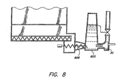
- feed means 606 and 706 cited above may be either combined with means for discharging pulp from a discharge chute of a drum or a disc washer or thickener as shown in FIGURES 6a, 6b, 7a, and 7b, or they may be, as shown in FIGURE 8, separate means 806 just for feeding pulp into the stand pipe 800.
- feed means 706 have been shown as an extension of a screw feeder used for discharging pulp from a drum or a disc filter or washer.
- FIGURES 6 through 8 show the combination of the stand pipe to a preceding washer, filter or thickener it should be understood that the stand pipe with its feed, discharge and pressurization means may be connected to all such positions where a stand pipe is needed.
- the positioning of the inlet opening in the wall of the stand pipe is not that critical except that it is desirably positioned below the pulp surface, or if the membrane is used, below the membrane.
Landscapes
- Paper (AREA)
- Polysaccharides And Polysaccharide Derivatives (AREA)
Claims (28)
- Procédé de traitement de pâte de cellulose, comprenant les étapes consistant à :(a) fixer une admission de pompe d'une pompe (30) à une ouverture d'évacuation (502, 602, 702) d'un tuyau vertical (500, 600, 700, 800),(b) faire parvenir (506, 606, 706, 806) la pâte de cellulose, présentant une consistance moyenne comprise entre environ 8 % et 18 % et une température élevée de l'ordre de 80 °C ou supérieure, d'une pression inférieure à travers une ouverture d'entrée (505, 605, 605', 705, 705') dans le tuyau vertical (500, 600, 700, 800), en utilisant des moyens pour transporter la pâte d'une pression inférieure à une pression supérieure,(c) mettre sous pression la pâte de cellulose dans le tuyau vertical (500, 600, 700, 800) de façon à fermer (504, 604, 704, 804) le tuyau vertical (500, 600, 700, 800) de l'atmosphère, et à prévoir (508, 608) une pression superatmosphérique dans le tuyau vertical (500, 600, 700, 800),(d) permettre à la pâte de cellulose de s'écouler dans la pompe de pâte (30) à travers l'admission de pompe,(e) pomper la pâte de cellulose davantage au moyen de la pompe de pâte (30), et(f) maintenir la pression superatmosphérique dans le tuyau vertical (500, 600, 700, 800) pour minimiser la formation de mousse au cours du pompage (30) de la pâte de cellulose.
- Procédé selon la revendication 1, caractérisé en ce que la pâte de cellulose présente une température proche de, ou supérieure à 100 °C.
- Procédé selon la revendication 1 ou 2, caractérisé par le fait que l'on fournit un espace de gaz (510, 610, 710) dans la partie supérieure du tuyau vertical (500, 600, 700, 800).
- Procédé selon l'une quelconque des revendications précédentes, caractérisé par le fait que l'on fait parvenir (506) la pâte depuis une partie d'extrémité supérieure du tuyau vertical (500) jusqu'à l'espace de gaz (510) et jusqu'au tuyau vertical (500).
- Procédé selon l'une quelconque des revendications précédentes, caractérisé par le fait que l'on fait parvenir (606, 706, 806) la pâte dans une extrémité inférieure du tuyau vertical (600, 700, 800).
- Procédé selon l'une quelconque des revendications précédentes, caractérisé par le fait que l'on fait parvenir (606) la pâte dans l'extrémité inférieure du tuyau vertical (600) et contre la pression de l'espace de gaz (610) à l'extrémité supérieure fermée du tuyau vertical (600) avant de pomper la pâte hors du tuyau vertical (600) au moyen de la pompe (30), mettant ainsi sous pression la pâte de cellulose dans le tuyau vertical (600).
- Procédé selon l'une quelconque des revendications précédentes, caractérisé par le fait que l'on fait parvenir (506) la pâte de cellulose d'une pression inférieure à la pression supérieure à l'intérieur du tuyau vertical (500), mettant ainsi sous pression la pâte de cellulose dans le tuyau vertical (500).
- Procédé selon l'une quelconque des revendications précédentes, caractérisé par le fait que l'on met sous pression la pâte de cellulose de façon à mettre sous pression l'espace de gaz (510, 610, 710).
- Procédé selon l'une quelconque des revendications précédentes, caractérisé par le fait que l'on met sous pression la pâte dans le tuyau vertical (600) de façon à délivrer (608) un fluide gazeux de pressurisation dans le tuyau vertical (600) de manière que l'espace de gaz (610) soit formé au-dessus de la pâte, et à forcer la pâte à l'admission de pompe sous l'effet à la fois de la gravité et de la pression du fluide.
- Procédé selon l'une quelconque des revendications précédentes, caractérisé par le fait que l'on met sous pression l'espace de gaz (510, 610, 710) et la pâte de cellulose de façon à extraire du gaz/de la vapeur de la pompe de pâte (30) pompant la pâte du tuyau vertical (500, 600, 700, 800) et en faisant parvenir ce gaz/cette vapeur de nouveau dans l'espace de gaz (510, 610, 710).
- Procédé selon la revendication 10, caractérisé par le fait que l'on fait parvenir le gaz/la vapeur de nouveau dans l'espace de gaz (510, 610, 710) avec l'air supplémentaire provenant de l'atmosphère.
- Procédé selon l'une quelconque des revendications précédentes, caractérisé par le fait que l'on sépare (508) du gaz de la pâte au cours du pompage (30) de la pâte.
- Procédé selon l'une quelconque des revendications précédentes, caractérisé en ce qu'on renvoie (509) le gaz séparé vers le tuyau vertical (500) en même temps qu'on met la pâte sous pression (508).
- Procédé selon l'une quelconque des revendications précédentes, caractérisé par le fait que l'on sépare physiquement la pâte du gaz pressurisé dans l'espace de gaz (710) au moyen d'une membrane (714).
- Dispositif pour traiter la pâte de cellulose, comprenant :un tuyau vertical (500, 600, 700, 800) présentant une partie supérieure et une partie inférieure, le tuyau vertical (500, 600, 700, 800) étant fermé (504, 604) de l'atmosphère et ayant un espace de gaz (510, 610, 710) dans la partie supérieure de celui-ci,des moyens d'alimentation (506, 606, 706, 806) pour faire parvenir la pâte d'une pression inférieure à la pression supérieure du tuyau vertical (500, 600, 700, 800), et le moyen d'alimentation (506, 606, 706, 806) est un moyen de rétention de la pression,des moyens de pressurisation (508, 608) pour mettre l'espace de gaz (510, 610, 710) et la pâte de cellulose dans le tuyau vertical (500, 600, 700, 800) sous pression et pour prévoir (508, 608) une pression superatmosphérique dans le tuyau vertical (500, 600, 700, 800), etune pompe de pâte (30) présentant une admission de pompe raccordée à la partie fond du tuyau vertical (500, 600, 700, 800) de manière que la pâte puisse s'écouler depuis la partie inférieure du tuyau vertical (500, 600, 700 800) jusqu'à l'entrée de pompe.
- Dispositif selon la revendication 15, caractérisé en ce que l'extrémité supérieure du tuyau vertical (500, 600, 700, 800) est fermée par un couvercle de pression (504, 604, 704, 804).
- Dispositif selon la revendication 15 ou 16, caractérisé en ce que le moyen d'alimentation est un dispositif d'alimentation à poche (506) ou une pompe volumétrique disposé au couvercle de pression (504) du tuyau vertical (500, 600, 700, 800) ou à une paroi ou à un logement de celui-ci.
- Dispositif selon l'une quelconque des revendications 15 à 17, caractérisé en ce que le moyen d'alimentation est un dispositif d'alimentation à vis (606, 706, 806) disposé à l'intérieur d'un tuyau d'entrée (609, 709) convergeant vers le tuyau vertical (500, 600, 700, 800).
- Dispositif selon l'une quelconque des revendications 15 à 18, caractérisé en ce que le moyen d'alimentation est un dispositif d'alimentation à vis (606, 706, 806) disposé de façon à transférer la pâte depuis un dispositif de lavage, un filtre ou un épaississeur jusqu'au tuyau vertical (500, 600, 700, 800).
- Dispositif selon l'une quelconque des revendications 15 à 19, caractérisé en ce que le moyen d'alimentation (706) est une extension d'un dispositif d'alimentation à vis utilisé pour évacuer la pâte d'un filtre à tambour ou à disques ou d'un dispositif de lavage.
- Dispositif selon l'une quelconque des revendications 15 à 20, caractérisé en ce que le moyen de pressurisation est un compresseur (608) ou un compresseur à suralimentation pompant de l'air extérieur, un autre gaz ou de la vapeur dans le tuyau vertical (500, 600).
- Dispositif selon l'une quelconque des revendications 15 à 21, caractérisé en ce que le moyen de pressurisation est une pompe à vide (508) extrayant du gaz ou de la vapeur de la pompe de pâte (30) pompant la pâte du tuyau vertical (500, 600, 700, 800).
- Dispositif selon l'une quelconque des revendications 15 à 22, caractérisé en ce que le moyen de pressurisation est le moyen d'alimentation (506, 606, 706, 806) pour faire parvenir la pâte d'une pression inférieure dans le tuyau vertical (500, 600, 700, 800).
- Dispositif selon l'une quelconque des revendications 15 à 23, caractérisé en ce que le moyen de pressurisation est un couvercle de pression (604, 704) du tuyau vertical (600, 700), le couvercle de pression (604, 704) fermant une extrémité supérieure du tuyau vertical (600, 700).
- Dispositif selon l'une quelconque des revendications 15 à 24, caractérisé en ce que le moyen de pressurisation est une pompe à vide (508) extrayant du gaz/de la vapeur de la pompe de pâte (30) et renvoyant ce gaz/cette vapeur dans l'espace de gaz (510, 610, 710).
- Dispositif selon l'une quelconque des revendications 15 à 25, caractérisé en ce que le tuyau vertical (500, 600, 700, 800) est raccordé de manière adjacente à une partie inférieure de celui-ci à l'admission de pompe.
- Dispositif selon l'une quelconque des revendications 15 à 26, caractérisé en ce que l'extrémité inférieure du tuyau vertical (500, 600, 700, 800) est pourvue d'une ouverture d'entrée de pâte (605, 605', 705, 705') pour recevoir la pâte.
- Dispositif selon l'une quelconque des revendications 15 à 27, caractérisé en ce que l'intérieur du tuyau vertical (700) est pourvu d'une membrane (714) fixée à la paroi sensiblement verticale du tuyau vertical, la membrane (714) séparant physiquement l'espace de pâte dans la partie inférieure du tuyau vertical (700) de l'espace de gaz (710) dans la partie supérieure du tuyau vertical (700).
Applications Claiming Priority (3)
| Application Number | Priority Date | Filing Date | Title |
|---|---|---|---|
| US927995P | 1995-12-27 | 1995-12-27 | |
| US9279P | 1995-12-27 | ||
| PCT/FI1996/000695 WO1997024486A1 (fr) | 1995-12-27 | 1996-12-23 | Pompage de pulpes de consistance moyenne et de temperature elevee a partir de colonnes d'alimentation |
Publications (2)
| Publication Number | Publication Date |
|---|---|
| EP0870083A1 EP0870083A1 (fr) | 1998-10-14 |
| EP0870083B1 true EP0870083B1 (fr) | 2004-07-07 |
Family
ID=21736684
Family Applications (1)
| Application Number | Title | Priority Date | Filing Date |
|---|---|---|---|
| EP96943144A Revoked EP0870083B1 (fr) | 1995-12-27 | 1996-12-23 | Pompage de pulpes de consistance moyenne et de temperature elevee a partir de colonnes d'alimentation |
Country Status (8)
| Country | Link |
|---|---|
| US (1) | US5851350A (fr) |
| EP (1) | EP0870083B1 (fr) |
| JP (1) | JP3839850B2 (fr) |
| AU (1) | AU1197297A (fr) |
| CA (1) | CA2241540C (fr) |
| DE (1) | DE69632869D1 (fr) |
| NO (1) | NO325304B1 (fr) |
| WO (1) | WO1997024486A1 (fr) |
Families Citing this family (4)
| Publication number | Priority date | Publication date | Assignee | Title |
|---|---|---|---|---|
| FI20002746A7 (fi) * | 2000-12-14 | 2002-06-15 | Andritz Oy | Menetelmä ja laite massan syöttämiseksi valkaisutorniin |
| FI20031164A7 (fi) * | 2003-07-09 | 2005-01-10 | Sulzer Pumpen Ag | Menetelmä ja laitteisto massan käsittelemiseksi |
| US8734611B2 (en) * | 2008-03-12 | 2014-05-27 | Andritz Inc. | Medium consistency refining method of pulp and system |
| SE532643C2 (sv) * | 2008-07-03 | 2010-03-09 | Metso Paper Inc | Förfarande och apparat för styrning av flöde av massasuspension |
Family Cites Families (6)
| Publication number | Priority date | Publication date | Assignee | Title |
|---|---|---|---|---|
| US2960161A (en) * | 1957-05-16 | 1960-11-15 | John C F C Richter | Device for discharging materials from vessels |
| US3096234A (en) * | 1958-10-29 | 1963-07-02 | Nolan | Continuous digesting system |
| US4884943A (en) * | 1987-06-25 | 1989-12-05 | A. Ahlstrom Corporation | Method and apparatus for pumping high-consistency fiber suspension |
| FI81136C (fi) * | 1987-11-11 | 1990-09-10 | Ahlstroem Oy | Foerfarande och anordning foer behandling av massa. |
| FI79361B (fi) * | 1988-01-05 | 1989-08-31 | Ahlstroem Oy | Foerfarande och apparatur foer underlaettande av uttoemning av fallroer eller liknande och behandling av massa i sagda utrymme. |
| US5411633A (en) * | 1991-04-30 | 1995-05-02 | Kamyr, Inc. | Medium consistency pulp ozone bleaching |
-
1996
- 1996-12-20 US US08/771,064 patent/US5851350A/en not_active Expired - Fee Related
- 1996-12-23 DE DE69632869T patent/DE69632869D1/de not_active Expired - Lifetime
- 1996-12-23 JP JP52404497A patent/JP3839850B2/ja not_active Expired - Fee Related
- 1996-12-23 CA CA002241540A patent/CA2241540C/fr not_active Expired - Fee Related
- 1996-12-23 AU AU11972/97A patent/AU1197297A/en not_active Abandoned
- 1996-12-23 WO PCT/FI1996/000695 patent/WO1997024486A1/fr not_active Ceased
- 1996-12-23 EP EP96943144A patent/EP0870083B1/fr not_active Revoked
-
1998
- 1998-06-26 NO NO19982979A patent/NO325304B1/no not_active IP Right Cessation
Also Published As
| Publication number | Publication date |
|---|---|
| JP3839850B2 (ja) | 2006-11-01 |
| CA2241540A1 (fr) | 1997-07-10 |
| WO1997024486A1 (fr) | 1997-07-10 |
| NO982979D0 (no) | 1998-06-26 |
| US5851350A (en) | 1998-12-22 |
| DE69632869D1 (de) | 2004-08-12 |
| NO982979L (no) | 1998-08-24 |
| CA2241540C (fr) | 2005-03-15 |
| AU1197297A (en) | 1997-07-28 |
| NO325304B1 (no) | 2008-03-25 |
| JP2000502759A (ja) | 2000-03-07 |
| EP0870083A1 (fr) | 1998-10-14 |
Similar Documents
| Publication | Publication Date | Title |
|---|---|---|
| US4410337A (en) | Method and an apparatus for separating a gas from a fibre suspension | |
| SE531498C2 (sv) | Matning av finfördelat fibermaterial | |
| SE0500751A1 (sv) | Matning av finfördelat fibermaterial | |
| CA2250490C (fr) | Systeme d'alimentation en suspension d'un recipient sous pression | |
| SE521099C2 (sv) | Separator, system och förfarande för avskiljning av icke önskat material från en slurry av finfördelat cellulosahaltigt fibermaterial i en vätska | |
| CA2052012C (fr) | Methode et appareil de separation des gaz de liquides contenant des solides | |
| JP2001020190A (ja) | 細砕セルロース繊維材処理装置へチップを供給するシステム、装置および方法。 | |
| EP0958433B1 (fr) | Cuve de desaeration | |
| CA2241540C (fr) | Pompage de pulpes de consistance moyenne et de temperature elevee a partir de colonnes d'alimentation | |
| EP0492040A1 (fr) | Réacteur rotatif à ozone pour pâte à papier | |
| US5106456A (en) | Method and apparatus for facilitating the discharge of pulp | |
| EP0440455A1 (fr) | Procédé et dispositif pour la séparation de gaz d'une suspension contenant du gaz | |
| NO175500B (no) | System og fremgangsmåte for pumping av suspensjoner | |
| US5567262A (en) | Two stage pressure diffuser | |
| US20070151691A1 (en) | Method for converting a digester for use as a gas phase and hydraulic phase continuous digester | |
| CN106103070A (zh) | 螺旋压榨机 | |
| CA1214686A (fr) | Regulation du fonctionnement d'une pompe centrifuge | |
| EP1592838B1 (fr) | Dispositif et procede destines au traitement de la pate a papier et procede destine a la modernisation d'un reservoir de stockage de pate a papier | |
| RU2352700C2 (ru) | Способ и устройство для переработки целлюлозы | |
| US5227058A (en) | Apparatus for removing liquid from the thickeners, filters, and washers | |
| SE530999C2 (sv) | Förfarande för behandling av finfördelat fibermaterial vid kokning av pappersmassa | |
| SE0950839A1 (sv) | System och metod för pumpmatning av flis till en kontinuerlig kokare | |
| JPS5920037B2 (ja) | 繊維材料処理方法 | |
| FI87538B (fi) | Foerfarande och anordning foer avlaegsnande av vaetska fraon faellningsanordningar, filterapparater, tvaettare och dylika | |
| EP0475669A2 (fr) | Tour de masse et appareil pour la vider |
Legal Events
| Date | Code | Title | Description |
|---|---|---|---|
| PUAI | Public reference made under article 153(3) epc to a published international application that has entered the european phase |
Free format text: ORIGINAL CODE: 0009012 |
|
| 17P | Request for examination filed |
Effective date: 19980626 |
|
| AK | Designated contracting states |
Kind code of ref document: A1 Designated state(s): DE FI SE |
|
| 17Q | First examination report despatched |
Effective date: 19981209 |
|
| RAP1 | Party data changed (applicant data changed or rights of an application transferred) |
Owner name: SULZER PUMPEN AG |
|
| GRAP | Despatch of communication of intention to grant a patent |
Free format text: ORIGINAL CODE: EPIDOSNIGR1 |
|
| GRAS | Grant fee paid |
Free format text: ORIGINAL CODE: EPIDOSNIGR3 |
|
| GRAA | (expected) grant |
Free format text: ORIGINAL CODE: 0009210 |
|
| AK | Designated contracting states |
Kind code of ref document: B1 Designated state(s): DE FI SE |
|
| REF | Corresponds to: |
Ref document number: 69632869 Country of ref document: DE Date of ref document: 20040812 Kind code of ref document: P |
|
| PLBI | Opposition filed |
Free format text: ORIGINAL CODE: 0009260 |
|
| PG25 | Lapsed in a contracting state [announced via postgrant information from national office to epo] |
Ref country code: DE Free format text: LAPSE BECAUSE OF FAILURE TO SUBMIT A TRANSLATION OF THE DESCRIPTION OR TO PAY THE FEE WITHIN THE PRESCRIBED TIME-LIMIT Effective date: 20041008 |
|
| REG | Reference to a national code |
Ref country code: SE Ref legal event code: TRGR |
|
| 26 | Opposition filed |
Opponent name: KVAERNER PULPING AB Effective date: 20040911 |
|
| PGFP | Annual fee paid to national office [announced via postgrant information from national office to epo] |
Ref country code: DE Payment date: 20041213 Year of fee payment: 9 |
|
| PLAX | Notice of opposition and request to file observation + time limit sent |
Free format text: ORIGINAL CODE: EPIDOSNOBS2 |
|
| PLBB | Reply of patent proprietor to notice(s) of opposition received |
Free format text: ORIGINAL CODE: EPIDOSNOBS3 |
|
| PGFP | Annual fee paid to national office [announced via postgrant information from national office to epo] |
Ref country code: FI Payment date: 20071214 Year of fee payment: 12 |
|
| PGFP | Annual fee paid to national office [announced via postgrant information from national office to epo] |
Ref country code: SE Payment date: 20071213 Year of fee payment: 12 |
|
| PLAB | Opposition data, opponent's data or that of the opponent's representative modified |
Free format text: ORIGINAL CODE: 0009299OPPO |
|
| R26 | Opposition filed (corrected) |
Opponent name: METSO FIBER KARLSTAD AB Effective date: 20040911 |
|
| RDAF | Communication despatched that patent is revoked |
Free format text: ORIGINAL CODE: EPIDOSNREV1 |
|
| RDAG | Patent revoked |
Free format text: ORIGINAL CODE: 0009271 |
|
| STAA | Information on the status of an ep patent application or granted ep patent |
Free format text: STATUS: PATENT REVOKED |
|
| 27W | Patent revoked |
Effective date: 20080910 |
|
| REG | Reference to a national code |
Ref country code: SE Ref legal event code: ECNC |