EP0870105B1 - Tuyere divergent deployable de propulseur - Google Patents
Tuyere divergent deployable de propulseur Download PDFInfo
- Publication number
- EP0870105B1 EP0870105B1 EP96944093A EP96944093A EP0870105B1 EP 0870105 B1 EP0870105 B1 EP 0870105B1 EP 96944093 A EP96944093 A EP 96944093A EP 96944093 A EP96944093 A EP 96944093A EP 0870105 B1 EP0870105 B1 EP 0870105B1
- Authority
- EP
- European Patent Office
- Prior art keywords
- diverging part
- ring
- divergent
- diverging
- arms
- Prior art date
- Legal status (The legal status is an assumption and is not a legal conclusion. Google has not performed a legal analysis and makes no representation as to the accuracy of the status listed.)
- Expired - Lifetime
Links
- 230000007246 mechanism Effects 0.000 claims description 13
- 238000011144 upstream manufacturing Methods 0.000 claims description 8
- 210000002105 tongue Anatomy 0.000 claims description 4
- 239000003380 propellant Substances 0.000 description 8
- 230000000903 blocking effect Effects 0.000 description 4
- 240000008042 Zea mays Species 0.000 description 3
- 230000002441 reversible effect Effects 0.000 description 2
- 230000006978 adaptation Effects 0.000 description 1
- 238000002485 combustion reaction Methods 0.000 description 1
- 239000002131 composite material Substances 0.000 description 1
- 230000007423 decrease Effects 0.000 description 1
- 229920001971 elastomer Polymers 0.000 description 1
- 239000000806 elastomer Substances 0.000 description 1
- 239000000463 material Substances 0.000 description 1
- 239000012528 membrane Substances 0.000 description 1
- 239000007769 metal material Substances 0.000 description 1
- 239000004449 solid propellant Substances 0.000 description 1
- 230000001360 synchronised effect Effects 0.000 description 1
Images



Classifications
-
- F—MECHANICAL ENGINEERING; LIGHTING; HEATING; WEAPONS; BLASTING
- F02—COMBUSTION ENGINES; HOT-GAS OR COMBUSTION-PRODUCT ENGINE PLANTS
- F02K—JET-PROPULSION PLANTS
- F02K9/00—Rocket-engine plants, i.e. plants carrying both fuel and oxidant therefor; Control thereof
- F02K9/97—Rocket nozzles
- F02K9/976—Deployable nozzles
-
- F—MECHANICAL ENGINEERING; LIGHTING; HEATING; WEAPONS; BLASTING
- F05—INDEXING SCHEMES RELATING TO ENGINES OR PUMPS IN VARIOUS SUBCLASSES OF CLASSES F01-F04
- F05D—INDEXING SCHEME FOR ASPECTS RELATING TO NON-POSITIVE-DISPLACEMENT MACHINES OR ENGINES, GAS-TURBINES OR JET-PROPULSION PLANTS
- F05D2250/00—Geometry
- F05D2250/30—Arrangement of components
- F05D2250/32—Arrangement of components according to their shape
- F05D2250/324—Arrangement of components according to their shape divergent
Definitions
- the subject of the present invention is a deployable divergent propellant.
- a solution consists in designing a deployable divergent having a reduced length in its initial configuration and which can be extended by placing one or more divergent rings.
- Deployable divergences are also used to allow adaptation of the thruster nozzle outlet section, depending on the ambient pressure, which decreases between low altitudes close to the ground and high altitudes, so that an optimal thrust is approached as much as possible despite altitude changes.
- the deployment of the deployable part of the divergent must be able to be carried out automatically and reliably with a minimum of energy expenditure.
- divergent deployables in particular mechanisms using systems with cables, roller screws, ball screws, roll-up beams or membrane.
- these mechanisms are relatively bulky and provide a very penalizing mass increase, especially in the case of diverging large diameters.
- the divergent includes a first part whose upstream end is connected to the bottom of the propellant and a second part in the form of a movable ring between a retracted position, in which it surrounds the first part of the diverging part, and a deployed position in which it connects to the downstream end of the first part to extend it.
- the deployment mechanism includes arms articulated, one end of which is connected to the diverging ring, and means actuation of the arms to move the divergent ring from its position retracted to its deployed position.
- the document FR 2 622 931 describes a deployment mechanism using three articulated arms whose movements are synchronized to guide precisely the divergent ring.
- the present invention aims to provide a deployable divergent of the type of that of US Patent 5,282,576, but in which the locking of the ring in the deployed position is produced reliably, without requiring a particular geometry of the arms, the deployment mechanism not being intended to be reversible.
- the deployable divergent according to the invention is thus remarkable for the combination of automatic locking of the diverging ring on the first divergent part, thanks to locking means distributed around their periphery, and the hyperstatic nature of the mobile assembly which makes it possible to guide the ring diverge precisely to the exact deployed position required for performs automatic locking.
- the locking means comprise a plurality of flexible tabs cooperating with one or more housings correspondents so as to snap into the housing (s) when the divergent ring reaches the deployed position.
- unlockable blocking means are designed to lock the divergent ring in the retracted position.
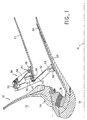
- the reference 10 designates a propellant body, for example a solid propellant propellant, including the combustion chamber 12 opens, through the bottom 14 of the propellant, by a nozzle neck 16 extended by a first part 20 of a deployable divergent.
- a propellant body for example a solid propellant propellant
- the combustion chamber 12 opens, through the bottom 14 of the propellant, by a nozzle neck 16 extended by a first part 20 of a deployable divergent.
- the upstream end of the divergent part 20, in the direction gas flow, and the nozzle neck 16 are connected to the bottom 14 of the propellant via a cone, in the case of a fixed nozzle or, in the illustrated case of an articulated nozzle, via a flexible stop 18.
- This is for example a spherical articulation stop formed, so known per se, of alternating layers of metal or composite material and of bonded elastomer.
- the body and bottom of the thruster, as well as the nozzle neck and the part 20 of divergent are normally coated internally with ablative material of thermal protection.
- the deployable divergent also comprises a divergent ring 22 which, in the retracted position (FIG. 1), surrounds the divergent part 20 while being coaxial with it and, in the deployed position (Figure 2), connects to the end downstream of the divergent part 20 and extends it so as to form a divergent with an enlarged outlet diameter.
- Each arm (FIGS. 1, 2, 3) has a first segment 32 articulated at a first end on a plate 36 fixed on the external wall of the first part of diverging part 20 (axis 33) and, at a second end, on a first end of a second segment 34 (axis 35). At its second end, the segment 34 is articulated on a plate 38 fixed to the outer wall of the diverging ring (axis 37).
- Each arm segment 32, 34 is formed by two sides, respectively 32 a , 32 b and 34 a , 34 b parallel to each other.
- the plane of symmetry P (FIG.
- a device for locking the arm in the retracted position comprises a stop 40 integral with the segment 32 and provided with a lug 42 which enters a housing 39 of the plate 38.
- the release of the lug 42 from the housing 39 to release the arm 30 can be achieved by pneumatic means, for example by connecting the lug to the piston of a pneumatic cylinder, or by pyrotechnic means. It is not necessary to provide a blocking device on each arm 30, the blocking of one arm being sufficient to keep the assembly in the retracted position.
- the arm 30 When the arm 30 is released, it can deploy with rotation of the segments 32, 34 around their end articulation axes. During the deployment of the arm, the position of the plane of symmetry P remains unchanged.
- the deployment of the arm 30 is carried out by means of a torsion spring 44 mounted on the hinge pin 33.
- the spring 44 drives a splined output shaft 45 engaged with segment 32.
- the four arms 30 are released simultaneously by unlocking the pins 42.
- the springs 44 thus released cause the simultaneous rotation of the arm segments 32 and thereby even the simultaneous deployment of the arms.
- the assembly formed by the four arms 30 and the ring of divergent 22 is hyperstatic, which makes the ring 22 move without deform and remain constantly centered on the axis A.
- the hyperstatic character mounting therefore ensures precise guidance of the diverging ring 22 towards the deployed position, a lack of synchronization of the arm movements being prevented. Note that this result can always be obtained by mounting a torsion spring on only some or even just one of the arms.
- the character hyperstatic here comes from the fact that four arms 30 are provided. The number of arms could be greater than four, but with a consequence mechanism does not really provide any additional benefit.
- means are provided at the periphery of the downstream end of the divergent part 20 and at the periphery of the upstream end of the diverging ring 22 to ensure their mutual locking when the diverging ring reaches position deployed.
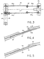
- these locking means are formed by a plurality of flexible tabs 50 which are fixed to the periphery of the downstream end of the divergent part 20, on the outside, and by an annular recess 52 formed at the upstream end of the diverging ring 22, on the inside.
- the internal wall 22 a of the ring 22 is supported on the tongues 50, causing them to bend towards the axis of the divergent (FIG. 4).
- the tongues 50 provide, in their free end part, a space 51 with the outer wall of the divergent part 20.
- the position of the tongues 50 is determined, as is that of the recess 52, so that the tabs snap into the recess 52 as soon as the divergent ring 22 reaches the deployed position ( Figure 5).
- the locking of the diverging ring 22 on the diverging part 20 is thus assured.
- the precision provided by the hyperstatic mounting allows this automatic locking mode.
- the drop 52 may be replaced by a plurality of housings corresponding to the tabs.
- the deployment of the arms is provided by one or more torsion springs.
- This solution is suitable when the divergent is deployed before ignition of the propellant, but the force developed by the spring or springs would normally be insufficient to oppose the pressure of the jet gas if deployment was ordered after ignition.
- the jack 60 can be of pneumatic or hydraulic type. It is possible to provide a single cylinder, the simultaneous movement of the other arms being ensured by hyperstatic mounting, or to provide several arms with a jack. The locking of the diverging ring 22 on the diverging part 20 is ensured as described with reference to Figures 4 and 5.
- tab locking mode and step shown in Figures 4 and 5 can easily be replaced by any other known means for locking or snap-fastening automatically.
Landscapes
- Engineering & Computer Science (AREA)
- Chemical & Material Sciences (AREA)
- Combustion & Propulsion (AREA)
- Mechanical Engineering (AREA)
- General Engineering & Computer Science (AREA)
- Aiming, Guidance, Guns With A Light Source, Armor, Camouflage, And Targets (AREA)
- Aerodynamic Tests, Hydrodynamic Tests, Wind Tunnels, And Water Tanks (AREA)
- Gyroscopes (AREA)
- Mutual Connection Of Rods And Tubes (AREA)
- Filling Or Discharging Of Gas Storage Vessels (AREA)
- Portable Nailing Machines And Staplers (AREA)
- Clamps And Clips (AREA)
Description
- des moyens sont prévus de façon répartie à la périphérie de l'extrémité aval de la première partie de divergent et à la périphérie de l'extrémité amont de l'anneau de divergent afin de permettre un verrouillage de l'anneau de divergent sur l'extrémité aval de la première partie de divergent lorsque l'anneau de divergent est en position déployée, et
- le mécanisme de déploiement comprend au moins quatre bras formant avec l'anneau de divergent un ensemble hyperstatique, de sorte que l'anneau peut être déplacé sans être sensiblement déformé afin d'être amené dans la position voulue pour se verrouiller automatiquement et complètement sur la première partie de divergent, lorsqu'il est déployé.
- la figure 1 est une demi-vue schématique en coupe montrant un divergent déployable selon un premier mode de réalisation de l'invention, avec l'anneau de divergent en position rétractée,
- la figure 2 est une demi-vue en coupe similaire à la figure 1, mais avec l'anneau de divergent en position déployée ;
- la figure 3 est une vue de dessus d'un bras du mécanisme de déploiement des figures 1 et 2 ;
- la figure 4 est une vue de détail montrant les moyens de verrouillage de l'anneau de divergent sur la première partie de divergent dans le divergent déployable des figures 1 et 2, immédiatement avant verrouillage ;
- la figure 5 est une vue de détail similaire à la figure 4, mais après verrouillage ;
- la figure 6 est une demi-vue schématique en coupe montrant un divergent déployable selon un deuxième mode de réalisation de l'invention, avec l'anneau de divergent en position rétractée ; et
- la figure 7 est une demi-vue en coupe similaire à la figure 1, mais avec l'anneau de divergent en position déployée.
Claims (8)
- Divergent déployable de propulseur, comprenant :caractérisé en ce que :une première partie de divergent (20) ayant une extrémité amont raccordée au fond (14) du propulseur,une deuxième partie de divergent (22) sous forme d'un anneau mobile entre une position rétractée dans laquelle il entoure la première partie de divergent (20) et une position déployée dans laquelle il se raccorde à l'extrémité aval de la première partie pour prolonger celle-ci, etun mécanisme de déploiement comportant plusieurs bras articulés (30) dont une extrémité est reliée à l'anneau de divergent, l'un des bras au moins étant muni de moyens (44 ; 60) d'actionnement permettant de déplacer l'anneau de divergent de sa position rétractée à sa position déployée,des moyens (50, 52) sont prévus de façon répartie à la périphérie de l'extrémié aval de la première partie de divergent et à la périphérie de l'extrémité amont de l'anneau de divergent afin de permettre un verrouillage de l'anneau de divergent (22) sur l'extrémité aval de la première partie de divergent (20) lorsque l'anneau de divergent est en position déployée, etle mécanisme de déploiement comprend au moins quatre bras (30) formant avec l'anneau de divergent (22) un ensemble hyperstatique, de sorte que l'anneau peut être déplacé sans être sensiblement déformé afin d'être amené dans la position voulue pour se verrouiller automatiquement et complètement sur la première partie de divergent (20), lorsqu'il est déployé.
- Divergent selon la revendication 1, caractérisé en ce que les moyens de verrouillage comprennent une pluralité de languettes flexibles (50) coopérant avec un ou plusieurs logements correspondants (52) de manière à venir s'encliqueter dans le ou les logements (52) lorsque l'anneau de divergent (22) parvient en position déployée.
- Divergent selon l'une quelconque des revendications 1 et 2, caractérisé en ce que des moyens de blocage déverrouillables sont prévus pour bloquer l'anneau de divergent (22) en position rétractée.
- Divergent selon la revendication 3, dans lequel chaque bras (30) comprend plusieurs segments articulés (32, 34), caractérisé en ce que les moyens de blocage (42, 39) sont agencés de manière à immobiliser un segment d'au moins un bras par rapport à un autre segment du même bras.
- Divergent selon l'une quelconque des revendications 1 à 4, caractérisé en ce que le déplacement des bras (30) en position déployée est réalisé par des moyens moteurs montés sur une articulation d'au moins un bras.
- Divergent selon la revendication 5, caractérisé en ce que les moyens moteurs sont constitués par un ressort de torsion.
- Divergent selon l'une quelconque des revendications 1 à 4, caractérisé en ce que le déplacement du bras (30) en position déployée est réalisé par des moyens moteurs agissant sur un segment d'au moins un bras (30).
- Divergent selon la revendication 7, caractérisé en ce que le déplacement des bras (30) en position déployée est réalisé au moyen d'au moins un vérin (60) monté entre la première partie de divergent (20) et un segment de bras articulé (30).
Applications Claiming Priority (3)
| Application Number | Priority Date | Filing Date | Title |
|---|---|---|---|
| FR9515634A FR2743110B1 (fr) | 1995-12-28 | 1995-12-28 | Divergent deployable de propulseur |
| FR9515634 | 1995-12-28 | ||
| PCT/FR1996/002093 WO1997024521A1 (fr) | 1995-12-28 | 1996-12-27 | Tuyere divergent deployable de propulseur |
Publications (2)
| Publication Number | Publication Date |
|---|---|
| EP0870105A1 EP0870105A1 (fr) | 1998-10-14 |
| EP0870105B1 true EP0870105B1 (fr) | 2002-11-27 |
Family
ID=9486067
Family Applications (1)
| Application Number | Title | Priority Date | Filing Date |
|---|---|---|---|
| EP96944093A Expired - Lifetime EP0870105B1 (fr) | 1995-12-28 | 1996-12-27 | Tuyere divergent deployable de propulseur |
Country Status (7)
| Country | Link |
|---|---|
| US (1) | US6205772B1 (fr) |
| EP (1) | EP0870105B1 (fr) |
| JP (1) | JP4070238B2 (fr) |
| DE (1) | DE69625081T2 (fr) |
| FR (1) | FR2743110B1 (fr) |
| UA (1) | UA37286C2 (fr) |
| WO (1) | WO1997024521A1 (fr) |
Families Citing this family (19)
| Publication number | Priority date | Publication date | Assignee | Title |
|---|---|---|---|---|
| FR2840030B1 (fr) * | 2002-05-21 | 2005-03-04 | Eads Launch Vehicles | Moteur a tuyere a noyau central pour lanceur spatial |
| KR100463056B1 (ko) * | 2002-10-08 | 2004-12-23 | 현대자동차주식회사 | 머플러의 가변 테일 파이프 구조 |
| DE10312776B4 (de) * | 2003-03-21 | 2008-10-02 | Eads Space Transportation Gmbh | Ausfahrbare Schubdüsenglocke für ein Raketentriebwerk |
| US7845708B2 (en) | 2007-06-06 | 2010-12-07 | Adaptive Aerodynamic, Llc | Aerodynamic drag reducing apparatus |
| US8627738B2 (en) * | 2005-06-29 | 2014-01-14 | Thomas Scott Breidenbach | Linear-curvilinear actuating apparatus with rotating joints |
| US7380868B2 (en) * | 2005-06-29 | 2008-06-03 | Thomas Scott Breidenbach | Aerodynamic drag reducing apparatus |
| US7374230B2 (en) * | 2005-12-01 | 2008-05-20 | Thomas Scott Breidenbach | Aerodynamic drag reducing apparatus |
| RU2296237C1 (ru) * | 2005-08-08 | 2007-03-27 | Открытое акционерное общество Научно-производственное объединение "Искра" | Раздвижное сопло ракетного двигателя |
| US7618086B2 (en) * | 2005-12-01 | 2009-11-17 | Thomas Scott Breidenbach | Aerodynamic drag reducing apparatus |
| US8360509B2 (en) | 2007-05-17 | 2013-01-29 | Advanced Transit Dynamics, Inc. | Rear-mounted aerodynamic structure for truck cargo bodies |
| US8100461B2 (en) | 2007-05-17 | 2012-01-24 | Advanced Transit Dynamics, Inc. | Rear-mounted aerodynamic structure for truck cargo bodies |
| US7857376B2 (en) | 2008-02-21 | 2010-12-28 | Adaptive Aerodynamic, Llc | Aerodynamic drag reducing apparatus |
| US9810085B2 (en) * | 2011-08-22 | 2017-11-07 | United Technologies Corporation | Flap seal for gas turbine engine movable nozzle flap |
| US9440689B1 (en) | 2011-09-20 | 2016-09-13 | Stemco Lp | Aerodynamic structures secured to the underbody of cargo bodies |
| WO2013043890A1 (fr) | 2011-09-20 | 2013-03-28 | Advanced Transit Dynamics, Inc. | Structure aérodynamique rétractable à montage arrière pour corps de chargement |
| CA2853727A1 (fr) | 2011-10-27 | 2013-05-02 | Advanced Transit Dynamics, Inc. | Structures aerodynamiques a montage arriere pour carrosseries pour marchandises |
| AU2013290151A1 (en) | 2012-07-11 | 2015-03-05 | Advanced Transit Dynamics, Inc. | Retractable aerodynamic structures for cargo bodies and methods of controlling positioning of the same |
| RU2647022C1 (ru) * | 2015-12-22 | 2018-03-13 | Акционерное общество "Корпорация "Московский институт теплотехники" (АО "Корпорация "МИТ") | Поворотное управляющее сопло с гибким раскладным насадком |
| US10815936B2 (en) | 2016-11-09 | 2020-10-27 | Northrop Grumman Innovation Systems, Inc. | Flexible bearing assemblies, rocket motors including such assemblies, and methods of forming flexible bearings |
Family Cites Families (7)
| Publication number | Priority date | Publication date | Assignee | Title |
|---|---|---|---|---|
| US3526365A (en) * | 1968-05-21 | 1970-09-01 | T O Paine | Collapsible nozzle extension for rocket engines |
| US3561679A (en) * | 1968-06-25 | 1971-02-09 | Sam E Lager | Collapsible nozzle for aircraft rocket motors |
| US4169555A (en) * | 1977-07-25 | 1979-10-02 | United Technologies Corporation | Extendible exit cone |
| US4213566A (en) * | 1978-08-25 | 1980-07-22 | Hercules Incorporated | Nested cone extendible nozzle system for a rocket motor |
| US4676436A (en) * | 1984-11-02 | 1987-06-30 | Unidynamics Phoenix, Inc. | Rocket motor nozzle extension system |
| FR2622931B1 (fr) * | 1987-11-10 | 1991-01-11 | Messerschmitt Boelkow Blohm | Mecanisme d'actionnement de tuyere de poussee prolongeable de moteur-fusee |
| FR2677080B1 (fr) * | 1991-05-30 | 1995-01-06 | Europ Propulsion | Mecanisme autoverrouillable et reversible de deploiement de divergent de tuyere de moteur-fusee. |
-
1995
- 1995-12-28 FR FR9515634A patent/FR2743110B1/fr not_active Expired - Fee Related
-
1996
- 1996-12-27 WO PCT/FR1996/002093 patent/WO1997024521A1/fr not_active Ceased
- 1996-12-27 UA UA98063314A patent/UA37286C2/uk unknown
- 1996-12-27 US US09/091,965 patent/US6205772B1/en not_active Expired - Lifetime
- 1996-12-27 JP JP52407797A patent/JP4070238B2/ja not_active Expired - Lifetime
- 1996-12-27 EP EP96944093A patent/EP0870105B1/fr not_active Expired - Lifetime
- 1996-12-27 DE DE69625081T patent/DE69625081T2/de not_active Expired - Lifetime
Also Published As
| Publication number | Publication date |
|---|---|
| JP4070238B2 (ja) | 2008-04-02 |
| FR2743110B1 (fr) | 1998-03-27 |
| DE69625081T2 (de) | 2003-10-30 |
| FR2743110A1 (fr) | 1997-07-04 |
| US6205772B1 (en) | 2001-03-27 |
| JP2000502773A (ja) | 2000-03-07 |
| EP0870105A1 (fr) | 1998-10-14 |
| UA37286C2 (uk) | 2001-05-15 |
| WO1997024521A1 (fr) | 1997-07-10 |
| DE69625081D1 (de) | 2003-01-09 |
Similar Documents
| Publication | Publication Date | Title |
|---|---|---|
| EP0870105A1 (fr) | Tuyere divergent deployable de propulseur | |
| EP0956441B1 (fr) | Divergent deployable pour propulseur | |
| EP3415749B1 (fr) | Nacelle avec système d'inverseur de poussée présentant des perturbations aérodynamiques limitées | |
| CA2169874C (fr) | Inverseur de poussee a volets aval pour turboreacteur | |
| FR2676779A1 (fr) | Tuyere a section variable. | |
| EP0646525A1 (fr) | Entrée d'air supersonique et hypersonique bidimensionnelle, à trois rampes mobiles, pour l'air de combustion d'un moteur d'aéronef | |
| FR3068081A1 (fr) | Systeme d'inverseur de poussee presentant des perturbations aerodynamiques limitees | |
| FR3018865A1 (fr) | ||
| EP0516519B1 (fr) | Mécanisme autoverrouillable et réversible de déploiement de divergent de tuyère de moteur-fusée | |
| WO1999005406A1 (fr) | Inverseur de poussee de turbosoufflante | |
| FR2790791A1 (fr) | Tuyere d'ejection de turboreacteur axisymetrique et a orientation globale | |
| FR2755729A1 (fr) | Turbomoteur a double flux pourvu d'une tuyere confluente et d'un inverseur de poussee | |
| EP0835999B1 (fr) | Inverseur de poussée à portes à installation de vérin de commande optimisée | |
| EP1045130A1 (fr) | Tuyère d'éjection axisymétrique, convergente divergente, à orientation par un anneau guide | |
| EP2414661B1 (fr) | Divergent deployable de propulseur | |
| CA2314169A1 (fr) | Tuyere d'ejection de turboreacteur, axisymetrique, convergente divergente a deviation de jet | |
| EP2188178B1 (fr) | Nacelle de turboréacteur, destinée à équiper un aéronef | |
| EP0604263B1 (fr) | Dispositif d'actionnement d'un organe mécanique, notamment pour le pilotage en force d'un missile, et missile équipé dudit dispositif | |
| EP3868667B1 (fr) | Nacelle d'aeronef comportant une rampe de soufflante avec des volets articules | |
| EP0685388B1 (fr) | Dispositif mécanique d'éjection comportant un piston mobile commandé en aller-retour | |
| EP4392655A1 (fr) | Inverseur a grilles mobiles pour ensemble propulsif d'aeronef, comprenant un systeme pour limiter le flambage d'un actionneur de l'inverseur | |
| EP2877732A1 (fr) | Dispositif d'entrainement de volets notamment pour tuyère adaptative | |
| EP4240959A1 (fr) | Partie arrière de turboréacteur comprenant une tuyère dont des volets comprennent des leviers déplaçables par des parois d'appui amont et aval | |
| FR2824106A1 (fr) | Manche a air et engin volant, en particulier un missile, muni d'une telle manche a air | |
| FR2907853A1 (fr) | Tuyere d'ejection des gaz pour turbomachine a double flux ayant une section d'ejection ou de col variable par deploiement de creneaux |
Legal Events
| Date | Code | Title | Description |
|---|---|---|---|
| PUAI | Public reference made under article 153(3) epc to a published international application that has entered the european phase |
Free format text: ORIGINAL CODE: 0009012 |
|
| 17P | Request for examination filed |
Effective date: 19980615 |
|
| AK | Designated contracting states |
Kind code of ref document: A1 Designated state(s): DE FR GB IT SE |
|
| 17Q | First examination report despatched |
Effective date: 20010125 |
|
| GRAG | Despatch of communication of intention to grant |
Free format text: ORIGINAL CODE: EPIDOS AGRA |
|
| GRAG | Despatch of communication of intention to grant |
Free format text: ORIGINAL CODE: EPIDOS AGRA |
|
| GRAH | Despatch of communication of intention to grant a patent |
Free format text: ORIGINAL CODE: EPIDOS IGRA |
|
| GRAH | Despatch of communication of intention to grant a patent |
Free format text: ORIGINAL CODE: EPIDOS IGRA |
|
| GRAA | (expected) grant |
Free format text: ORIGINAL CODE: 0009210 |
|
| AK | Designated contracting states |
Kind code of ref document: B1 Designated state(s): DE FR GB IT SE |
|
| REG | Reference to a national code |
Ref country code: GB Ref legal event code: FG4D Free format text: NOT ENGLISH |
|
| REF | Corresponds to: |
Ref document number: 69625081 Country of ref document: DE Date of ref document: 20030109 |
|
| GBT | Gb: translation of ep patent filed (gb section 77(6)(a)/1977) |
Effective date: 20030327 |
|
| PLBE | No opposition filed within time limit |
Free format text: ORIGINAL CODE: 0009261 |
|
| STAA | Information on the status of an ep patent application or granted ep patent |
Free format text: STATUS: NO OPPOSITION FILED WITHIN TIME LIMIT |
|
| 26N | No opposition filed |
Effective date: 20030828 |
|
| PGFP | Annual fee paid to national office [announced via postgrant information from national office to epo] |
Ref country code: SE Payment date: 20061127 Year of fee payment: 11 |
|
| PGFP | Annual fee paid to national office [announced via postgrant information from national office to epo] |
Ref country code: IT Payment date: 20061231 Year of fee payment: 11 |
|
| EUG | Se: european patent has lapsed | ||
| PG25 | Lapsed in a contracting state [announced via postgrant information from national office to epo] |
Ref country code: SE Free format text: LAPSE BECAUSE OF NON-PAYMENT OF DUE FEES Effective date: 20071228 |
|
| PG25 | Lapsed in a contracting state [announced via postgrant information from national office to epo] |
Ref country code: IT Free format text: LAPSE BECAUSE OF NON-PAYMENT OF DUE FEES Effective date: 20071227 |
|
| REG | Reference to a national code |
Ref country code: DE Ref legal event code: R082 Ref document number: 69625081 Country of ref document: DE Representative=s name: CBDL PATENTANWAELTE, DE |
|
| REG | Reference to a national code |
Ref country code: DE Ref legal event code: R082 Ref document number: 69625081 Country of ref document: DE Representative=s name: CBDL PATENTANWAELTE, DE |
|
| REG | Reference to a national code |
Ref country code: DE Ref legal event code: R082 Ref document number: 69625081 Country of ref document: DE Representative=s name: CBDL PATENTANWAELTE, DE |
|
| REG | Reference to a national code |
Ref country code: DE Ref legal event code: R082 Ref document number: 69625081 Country of ref document: DE Representative=s name: CBDL PATENTANWAELTE, DE Effective date: 20130111 Ref country code: DE Ref legal event code: R082 Ref document number: 69625081 Country of ref document: DE Representative=s name: CBDL PATENTANWAELTE, DE Effective date: 20130115 Ref country code: DE Ref legal event code: R082 Ref document number: 69625081 Country of ref document: DE Representative=s name: CBDL PATENTANWAELTE, DE Effective date: 20130114 Ref country code: DE Ref legal event code: R082 Ref document number: 69625081 Country of ref document: DE Representative=s name: CBDL PATENTANWAELTE, DE Effective date: 20130117 Ref country code: DE Ref legal event code: R081 Ref document number: 69625081 Country of ref document: DE Owner name: HERAKLES, FR Free format text: FORMER OWNER: LEXVALL, PARIS, FR Effective date: 20130114 Ref country code: DE Ref legal event code: R081 Ref document number: 69625081 Country of ref document: DE Owner name: HERAKLES, FR Free format text: FORMER OWNER: SOCIETE NATIONALE D'ETUDE ET DE CONSTRUCTION DE MOTEURS D'AVIATION, PARIS, FR Effective date: 20130111 Ref country code: DE Ref legal event code: R081 Ref document number: 69625081 Country of ref document: DE Owner name: HERAKLES, FR Free format text: FORMER OWNER: SNECMA MOTEURS, PARIS, FR Effective date: 20130114 Ref country code: DE Ref legal event code: R081 Ref document number: 69625081 Country of ref document: DE Owner name: HERAKLES, FR Free format text: FORMER OWNER: SNECMA PROPULSION SOLIDE, LE HAILLAN, FR Effective date: 20130117 Ref country code: DE Ref legal event code: R081 Ref document number: 69625081 Country of ref document: DE Owner name: HERAKLES, FR Free format text: FORMER OWNER: LEXVALL 8, VELIZY-VILLACOUBLAY, FR Effective date: 20130115 |
|
| REG | Reference to a national code |
Ref country code: FR Ref legal event code: TP Owner name: HERAKLES, FR Effective date: 20130513 Ref country code: FR Ref legal event code: CD Owner name: HERAKLES, FR Effective date: 20130513 Ref country code: FR Ref legal event code: CA Effective date: 20130513 |
|
| PGFP | Annual fee paid to national office [announced via postgrant information from national office to epo] |
Ref country code: DE Payment date: 20131121 Year of fee payment: 18 Ref country code: GB Payment date: 20131125 Year of fee payment: 18 |
|
| PGFP | Annual fee paid to national office [announced via postgrant information from national office to epo] |
Ref country code: FR Payment date: 20131209 Year of fee payment: 18 |
|
| REG | Reference to a national code |
Ref country code: DE Ref legal event code: R119 Ref document number: 69625081 Country of ref document: DE |
|
| GBPC | Gb: european patent ceased through non-payment of renewal fee |
Effective date: 20141227 |
|
| REG | Reference to a national code |
Ref country code: FR Ref legal event code: ST Effective date: 20150831 |
|
| PG25 | Lapsed in a contracting state [announced via postgrant information from national office to epo] |
Ref country code: GB Free format text: LAPSE BECAUSE OF NON-PAYMENT OF DUE FEES Effective date: 20141227 Ref country code: DE Free format text: LAPSE BECAUSE OF NON-PAYMENT OF DUE FEES Effective date: 20150701 |
|
| PG25 | Lapsed in a contracting state [announced via postgrant information from national office to epo] |
Ref country code: FR Free format text: LAPSE BECAUSE OF NON-PAYMENT OF DUE FEES Effective date: 20141231 |