EP0870180B1 - Optisches bauelement zur polarisationsmodulation, und dessen verwendung in einem polarimeter oder ellipsometer - Google Patents
Optisches bauelement zur polarisationsmodulation, und dessen verwendung in einem polarimeter oder ellipsometer Download PDFInfo
- Publication number
- EP0870180B1 EP0870180B1 EP97910494A EP97910494A EP0870180B1 EP 0870180 B1 EP0870180 B1 EP 0870180B1 EP 97910494 A EP97910494 A EP 97910494A EP 97910494 A EP97910494 A EP 97910494A EP 0870180 B1 EP0870180 B1 EP 0870180B1
- Authority
- EP
- European Patent Office
- Prior art keywords
- modulator
- polarisation
- phase
- matrix
- incident beam
- Prior art date
- Legal status (The legal status is an assumption and is not a legal conclusion. Google has not performed a legal analysis and makes no representation as to the accuracy of the status listed.)
- Expired - Lifetime
Links
Images
Classifications
-
- G—PHYSICS
- G01—MEASURING; TESTING
- G01N—INVESTIGATING OR ANALYSING MATERIALS BY DETERMINING THEIR CHEMICAL OR PHYSICAL PROPERTIES
- G01N21/00—Investigating or analysing materials by the use of optical means, i.e. using sub-millimetre waves, infrared, visible or ultraviolet light
- G01N21/17—Systems in which incident light is modified in accordance with the properties of the material investigated
- G01N21/21—Polarisation-affecting properties
- G01N21/211—Ellipsometry
-
- G—PHYSICS
- G01—MEASURING; TESTING
- G01J—MEASUREMENT OF INTENSITY, VELOCITY, SPECTRAL CONTENT, POLARISATION, PHASE OR PULSE CHARACTERISTICS OF INFRARED, VISIBLE OR ULTRAVIOLET LIGHT; COLORIMETRY; RADIATION PYROMETRY
- G01J4/00—Measuring polarisation of light
- G01J4/04—Polarimeters using electric detection means
-
- G—PHYSICS
- G01—MEASURING; TESTING
- G01J—MEASUREMENT OF INTENSITY, VELOCITY, SPECTRAL CONTENT, POLARISATION, PHASE OR PULSE CHARACTERISTICS OF INFRARED, VISIBLE OR ULTRAVIOLET LIGHT; COLORIMETRY; RADIATION PYROMETRY
- G01J4/00—Measuring polarisation of light
-
- G—PHYSICS
- G01—MEASURING; TESTING
- G01J—MEASUREMENT OF INTENSITY, VELOCITY, SPECTRAL CONTENT, POLARISATION, PHASE OR PULSE CHARACTERISTICS OF INFRARED, VISIBLE OR ULTRAVIOLET LIGHT; COLORIMETRY; RADIATION PYROMETRY
- G01J9/00—Measuring optical phase difference; Determining degree of coherence; Measuring optical wavelength
-
- G—PHYSICS
- G02—OPTICS
- G02F—OPTICAL DEVICES OR ARRANGEMENTS FOR THE CONTROL OF LIGHT BY MODIFICATION OF THE OPTICAL PROPERTIES OF THE MEDIA OF THE ELEMENTS INVOLVED THEREIN; NON-LINEAR OPTICS; FREQUENCY-CHANGING OF LIGHT; OPTICAL LOGIC ELEMENTS; OPTICAL ANALOGUE/DIGITAL CONVERTERS
- G02F1/00—Devices or arrangements for the control of the intensity, colour, phase, polarisation or direction of light arriving from an independent light source, e.g. switching, gating or modulating; Non-linear optics
- G02F1/01—Devices or arrangements for the control of the intensity, colour, phase, polarisation or direction of light arriving from an independent light source, e.g. switching, gating or modulating; Non-linear optics for the control of the intensity, phase, polarisation or colour
- G02F1/03—Devices or arrangements for the control of the intensity, colour, phase, polarisation or direction of light arriving from an independent light source, e.g. switching, gating or modulating; Non-linear optics for the control of the intensity, phase, polarisation or colour based on ceramics or electro-optical crystals, e.g. exhibiting Pockels effect or Kerr effect
- G02F1/0327—Operation of the cell; Circuit arrangements
-
- G—PHYSICS
- G01—MEASURING; TESTING
- G01J—MEASUREMENT OF INTENSITY, VELOCITY, SPECTRAL CONTENT, POLARISATION, PHASE OR PULSE CHARACTERISTICS OF INFRARED, VISIBLE OR ULTRAVIOLET LIGHT; COLORIMETRY; RADIATION PYROMETRY
- G01J9/00—Measuring optical phase difference; Determining degree of coherence; Measuring optical wavelength
- G01J2009/006—Measuring optical phase difference; Determining degree of coherence; Measuring optical wavelength using pulses for physical measurements
Definitions
- the subject of the present invention is a component modulation optics, a polarimeter and an ellipsometer Mueller comprising such an optical component, a method of calibration of this ellipsometer and a measurement method ellipsometric.
- ellipsometry To measure quantities representative of a sample, such as optical, physical quantities, chemical or electrical, it is conventional to use ellipsometry.
- the scope of ellipsometry standard is however restricted to materials not depolarizing, isotropic and presenting a plane interface.
- Generalized ellipsometry allows to measure materials not isotropic, but only if they are not depolarizing.
- materials depolarizers for example rough or particulate.
- the polarization states of light can be represented by a vector of dimension 4, which is conventionally the Stokes S vector of light.
- the Stokes vector includes the coordinates I, Q, U, V, respectively representative of average intensities of four polarization states different.
- Any medium can then be represented by a real matrix of dimensions 4 x 4 which describes the couplings in intensities of the different modes of light polarization, these couplings being caused by the interaction of light with the middle.
- This matrix includes sixteen generally independent coefficients others.
- Mueller ellipsometry is equivalent to measuring the Mueller matrix complete with the medium studied. She is so particularly applicable to deposits on rough surfaces or particle measurements, which other processes ellipsometric measurement are not appropriate.
- the devices used for Mueller ellipsometry, or Mueller ellipsometers commonly include a light source, a generator of polarization states or PSG (Polarization States Generator) and a state detector polarization or PSD (Polarization States Detector), also called a polarimeter.
- PSG Polarization States Generator
- PSD Polarization States Detector
- a beam is emitted luminous with the source, we give the beam states of polarization with the PSG, we send the beam on the sample to be measured, then the beam obtained is detected with the PSD.
- polarizers and quarter wave blades fixed in the PSG and the PSD in their giving sixteen different configurations to measure the Mueller matrix of the sample. This manual technique is however difficult to use and ineffective.
- the measurement system includes two piezoelastic modulators, working at the same frequency, coupled in phase and having an angular deviation of their orientations equal to 45 °, a super-achromatic plate ⁇ / 4 and a linear polarizer, the modulators, the plate and the polarizer being successively arranged on a path optical.
- This system poses synchronization problems modulators and their coupling control. Moreover, he has the disadvantage of being sensitive to noise.
- the present invention relates to a Mueller ellipsometer allowing high frequency modulation, simple to implementing and giving simultaneous measurements and of the sixteen coefficients of the Mueller matrix
- the invention also relates to such an ellipsometer which may, individually or cumulatively, be insensitive to ambient noise, offer spectroscopic capabilities, allow modulation at such high frequencies than 100 MHz and be usable for time measurements real for example of growth of layers on substrate.
- the object of the invention is a method of calibration of a Mueller ellipsometer targeted by the invention, this process being at the same time precise, fast and easy to implement artwork.
- the object of the invention is also a measurement method Mueller ellipsometric simple to implement and giving simultaneous and precise measurements of the sixteen Mueller matrix coefficients, which can be set works at high modulation frequencies.
- the invention also relates to an optical component of modulation that can be used in the PSG, and possibly also in the PSD, an ellipsometer of Mueller. More generally, the object of the invention is to optical modulation component allowing modulations high frequencies and simple to implement.
- the invention also relates to a usable PSD or polarimeter in any device requiring the measurement of polarization light, especially in a Mueller ellipsometer, can be used at high frequencies and easy to use.
- the invention relates to a component polarization modulation optics comprising a polarization modulator which modulates an incident beam of linearly polarized light and returns a modulated beam.
- the polarization modulator is a phase modulator coupled modulating the incident beam twice successively, the two modulations being strictly at the same frequency ⁇ / 2 ⁇ and being coupled.
- the modulations are coupled by a system modifying the polarization state of the light between the two modulations.
- the two modulations are "strictly" at the same frequency in the sense that they have a phase shift between them relative which is fixed in time, and therefore do not undergo is drifting away from each other.
- This strict identity is preferably obtained by an external servo or by the double use of the same modulator.
- Coupled modulations we mean identical modulations (i.e. having the same frequency and a fixed relative phase shift over time) which cannot be reduced to a single phase modulation. So, the two modulations do not apply to the same components of the Stokes vector. Specifically, each phase modulation being applied according to a subspace two-dimensional vector of the vector space of four-dimensional polarization in which the Stokes vector of the incident beam, the two subspaces associated with the two modulations respectively are not confused.
- the modulations are coupled by means of a coupling system, not a simple angular deviation between the modulation directions.
- the coupling system is type partial polarizer and phase shifter or PPS (Partial Polarizer and phase Shifter).
- PPS Partial Polarizer and phase Shifter
- phase modulator is said to be “coupled” by reference to the two coupled phase modulations that it applied.
- the optical component applies a polarization modulation such that the vector of Stokes S of the modulated beam is expressed linearly in function of a harmonic basis of the pulsation ⁇ by a row matrix 4.
- the coupled modulator comprises a phase modulator producing the two modulations successive and a polarizer type coupling system partial and phase shifter.
- the phase modulator produces the first modulation and sends the incident beam to the coupling system, the coupling system returns the incident beam to the phase modulator and the phase modulator produces the second modulation.
- This embodiment is particularly advantageous in that it allows modulation at high frequency the four components of the Stokes vector, including the average intensity I. Consequently, when used in a PSG, it offers a low level of detection and makes no need to use a chopper.
- the incident beam light being linearly polarized in a polarization direction
- the phase modulator and the coupling system are oriented at 45 ° and 90 ° from the direction of polarization.
- the coupled modulator includes two phase modulators producing respectively the same two successive modulations, the two phase modulators with the same orientation, and a coupling system of the partial polarizer type and phase shifter interposed between the two phase modulators.
- the coupling system sends the incident beam from the first to the second of the phase modulators.
- the two phase modulators are preferably electro-optical.
- This other embodiment makes it possible to modulate high frequency the four components of the vector of Stokes, as the first embodiment.
- the coupling system sends the incident beam, we mean that it can either transmit it, either reflect it.
- the light of the incident beam being linearly polarized in a polarization direction
- the phase modulators, on the one hand, and the coupling system on the other hand are oriented respectively at 45 ° and 90 ° from the direction of polarization.
- the coupling system works in reflection and has a first polarization element partial and a second phase shift and reflection element.
- the first element consists of a stack of interfaces air-glass at the Brewster angle and the second element is formed by a prism.
- the invention also relates to a polarimeter comprising an optical component according to the invention.
- Such a PSD or polarimeter can be used by example in a Mueller ellipsometer, the PSG including a polarization modulator.
- the polarization modulator is included in an optical component according to the invention.
- the detection means include a polarimeter comprising detection means making it possible to produce n measured quantities representing the states of polarization of the measurement beam and in that the processing unit includes means for producing Fourier transform m values for each n measured quantities, with n x m ⁇ 16 and m ⁇ 4, giving access to the sixteen coefficients of the matrix of Mueller.
- the Mueller ellipsometer according to the invention is based therefore on phase modulations at a single frequency. he eliminates any rotating element and performs high frequency measurements, as well as getting a simple implementation and precise results. In addition, it can easily be adapted on existing systems classic phase modulation ellipsometry and take advantage digital processing techniques therein usually used.
- the light source and the polarizer must be considered to be equivalent to a light source linearly polarized.
- the detection means can include one or more several photodetectors.
- n 1 and m ⁇ 16 and the polarimeter includes a polarization modulation system.
- This system of modulation can in particular be the optical component according to the invention.
- the detected light intensity is then time dependent.
- the second case is that of a multi-channel technique, particularly advantageous for performing the simultaneous measurement of coefficients using only one polarization modulation in the PSG.
- the polarimeter can then separate the measurement beam into several beams secondary, each with a distinct state of polarization and being detected by one of the photodetectors, or producing consecutive reflections of the measurement beam on different photodetectors.
- the PSD or polarimeter has a structure such that it does not introduce any new time modulation, the measured quantities being linearly related to the four components of the Stokes vector.
- the quantities measured depend on time and are usually intensities measured by the photodetectors.
- harmonics of the pulsation ⁇ and calculate with the processing unit the harmonic components of corresponding orders of each of the quantities measured.
- the values produced are then the harmonic coordinates of the quantities measured according to the fixed harmonic components.
- the number minimum of harmonic coordinates per measured quantity to get the sixteen coefficients of the Mueller matrix is 4, a higher number of harmonic coordinates involving redundancies in determining these coefficients.
- the product of the Mueller matrix M by the Stokes vector S 1 of the beam incident on the sample is equal to the Stokes vector S 2 of the measurement beam emerging from the sample.
- the Mueller ellipsometer PSG is made up of the polarizer and the polarization modulator, while the PSD is made up of the detection means.
- the PSG and the PSD respectively have a modulation matrix W and a detection matrix A, the latter may or may not vary over time.
- the measured quantities being grouped in a quantity vector P the product of the detection matrix A by the Stokes vector S 2 of the measurement beam returned by the sample is equal to the quantity vector P.
- a 0 2.791.
- the components of the harmonic vector H (t) are the most independent.
- the matrices W, M and A have dimensions 4 x m, 4 x 4 and n x 4.
- the PSG and the PSD can correspond indifferently to one of the modes of realization described above, the PSD modulating the polarization at a frequency 5 times greater or less than that of PSG.
- the modulation matrix W is necessarily of rank 4 (W T W invertible), the PSG is then said to be complete.
- the detection matrix A must also be of rank 4, in the case where it is invariant in time.
- n ⁇ 4 and the polarimeter has a structure such that it does not introduce no new time modulation.
- the detection matrix A then being invariant during the time and rank 4.
- the ellipsometer provides a great simplicity of use and high capacities frequencies (no moving parts), allows to shoot take full advantage of existing multichannel techniques and is particularly effective and easy to use.
- the polarimeter separates the four polarization states of the measurement beam associated with four measured quantities.
- This advantageous form corresponds to the minimum configuration not introducing modulation in exit.
- the ellipsometer comprising in the PSG an optical component according to the invention, the four values produced by Fourier transform for each measured quantity depending on time t are then advantageously the harmonic coordinates of this quantity measured in the base: cos ⁇ t, sin ⁇ t, cos 2 ⁇ t, sin 2 ⁇ t.
- the processing unit has a structure such that it produces the m values for each of the n quantities measured I h (t) by means of a special Fourier transform according to which, the interval [0.2 ⁇ / ⁇ ] being discretized in 2N points T K equi-distributed and the quantity measured I h (t) being calculated at sampling instants t k , for k varying from 0 to 2N-1, the processing unit evaluates the j-th harmonic component B hj of the function I h , for j varying from 1 to m and h varying from 1 to n by: the functions g j (t) being selected demodulation functions such as the demodulation matrix D given by: for l and j varying from 1 to m, is of rank ⁇ 4.
- the sampling points t k are not evenly distributed, so that the measurements must be triggered over each period at precise predetermined times.
- the SFFT1 therefore requires an adaptation of the hardware elements of the processing unit (hardware), but makes it possible to keep the same software (software).
- SFFT1 provides a phase shift ⁇ (t) equal to ⁇ t (modulo 2 ⁇ ) over a period, whatever phase modulators used. It gives very good results precise while avoiding the appearance of singularities.
- the demodulation functions g j (t) thus constitute the dual basis of the harmonic coordinates H l (t) of calculation.
- the nature of the functions g j therefore differs, depending on whether the polarization modulator comprises electro-optical or photoelastic modulators.
- the SFFT2 makes it possible to keep the material (hardware) unchanged compared to a conventional FFT, because the sampling points t k are equally distributed. However, it requires a modification of the software (software) of the processing unit.
- the demodulation obtained with SFFT2 gives a optimal signal-to-noise ratio and cross-talk minimal.
- the detection means and the processing unit are advantageously adapted to spectroscopic measurements.
- Perform a measurement with the entity corresponding to the identity matrix means not putting any sample between the PSG and PSD.
- This process makes it possible to measure at high frequency the complete Mueller matrix of the sample, with precision and in a simple way.
- Demodulation can be performed by a fast Fourier transform or FFT (Fast Fourier Transform) standard or by SFFT.
- FFT Fast Fourier Transform
- SFFT Fast Fourier Transform
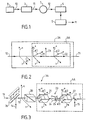
- a Mueller ellipsometer shown in Figure 1, includes a light source 2 emitting an incident beam 10 and a generator of polarization or PSG 3, which transforms in a controlled manner the polarization state of the incident beam 10.
- PSG 3 linearly polarizes the incident beam 10 and applies to it a polarization modulation. It transmits the beam modulated incident 11 to a sample 1 to be measured.
- PSD 4 state detector polarization or PSD 4, which detects a measurement beam 12 returned by sample 1 and a processing unit 5 receiving electrical signals produced by the PSD 4.
- the PSG 3A includes a linear polarizer 20 and a modulator coupled 6A comprising two phase modulators 21 and 22 and a coupling system 23 of the partial polarizer type and phase shifter.
- the two phase modulators 21 and 22 have a same orientation and the coupling system 23 is interposed between them and transmits the incident beam 10 of the first phase modulator 21 to the second phase modulator 22.
- the orientations of the different elements are as follows.
- the incident beam 10 having a direction and a direction of propagation and an incident plane being defined from this direction of propagation and from the sample 1, a reference frame is formed comprising a first axis x perpendicular to the direction of propagation and in the plane of incidence, a second axis y perpendicular to the plane of incidence and a third axis parallel to the direction of propagation and oriented in the same direction, this reference being direct.
- the polarizer 20 is then a perfect polarizer oriented along the y axis.
- the two phase modulators 21 and 22 are identical and oriented in the xy plane in directions forming respectively with the y axis angles ⁇ 1 and ⁇ 2 .
- the angles ⁇ 1 and ⁇ 2 are advantageously identical and preferably equal to ⁇ / 4.
- the coupling system 23 is oriented along the x axis.
- the incident beam 10 is polarized linearly by polarizer 20, then undergoes a double coupled modulation due to phase modulators 21, 22 and the coupling system 23.
- the coupling system 23 performs two functions: partial polarization (polarizer imperfect) which modulates the average intensity l and a phase shift which mixes the U and V components of the Stokes S vector.
- the polarizer 20 is a polarizer marketed as "Glan Polarizer” Thomson "and the phase modulators 21, 22 are electro-optical modulators of the Pockels cell type.
- the use of electro-optical modulators makes it possible absolute phase control which allows synchronization phase modulators 21 and 22.
- the double 6A modulator also includes cells marketed as Peltier cells, thermally regulating the cells of Pockels.
- the coupling system 23 advantageously comprises two transparent blades 24 and 25 covered with a very thin layer of gold, oriented to avoid generating a beam offset. It receives the beam 10 with an angle of incidence preferably equal to 60 °, linked to ⁇ 0 (angle between the direction of propagation and the orientation of the first plate 24).
- the transmission coupling system 23 can be replaced by a coupling system in reflection, by example in the form of a chrome mirror.
- the PSG 3A also includes a separator 27 of beams, arranged in the path of the modulated incident beam 11 after the modulators 21, 22.
- This separator 27 takes a control beam 15, used to act on the modulations in order to compensate for parasitic fluctuations.
- the separator 27 takes 4% of the intensity light in the control beam 15. It can be of a glass slide inclined at 45 ° from the direction of spread.
- the light source 2 emits laser beams 13, 14 at several wavelengths.
- the ellipsometer then comprises a movable mirror 26 allowing to select the desired wavelength.
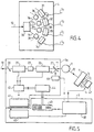
- the PSD 4 advantageously comprises a beam splitter 30 separating the measurement beam 12 into at least four secondary beams 16-19.
- the PSD 4 also includes polarization analyzers 36-39 giving each of these secondary beams 16-19 a separate polarization state and photodetectors 31-34 respectively detecting the intensities I 1 to I 4 of the secondary beams 16-19.
- the associated polarization analyzers 36-39 are respectively nothing, a linear polarizer at 90 °, a linear polarizer at -45 ° and the association of a quarter wave plate at 45 ° and a polarizer at 90 °.
- control and signal processing assembly will now be detailed, with reference to FIG. 5.
- PSG 3A includes a signal generator 41 connected to modulators 21 and 22 via a amplifier 42.
- This signal generator 41 applies by through amplifier 42 an aux voltage modulators 21, 22.
- This voltage is reflected on the beam 10 by a phase shift ⁇ of the polarization, proportional to this voltage over time t.
- this phase shift ⁇ consists of ramps of period 2 ⁇ / ⁇ and slope ⁇ over each period. In this way, any function periodic of ⁇ (t) of period 2 ⁇ is the same function of ⁇ t.
- the processing unit 5 comprises a data signal processor 40 or DSP (Data Signal Processor), which receives electrical signals from the PSD 4.
- the PSD 4 can be connected to the DSP 40 by a multiplexer 47, or by any other known means.
- the DSP 40 calculates the desired harmonic coordinates of the intensities of the secondary beams 16-19 measured.
- the harmonics of calculation are the four of orders 1 and 2: cos ⁇ t, sin ⁇ t, cos 2 ⁇ t, sin 2 ⁇ t.
- the DSP 40 calculates harmonic coordinates in a base with more of four harmonics, grouping for example the precedents and harmonics of orders greater than 2.
- the DSP 40 is equipped with an analog converter digital or ADC (Analogic Digital Converter) which provides values of the electrical signals from the PSD 4 in sampling points, as well as a memory of the FIFO type, which averages these values over several periods before they are processed by DSP 40.
- the sampling includes for example sixteen points per period.
- the processing unit 5 also includes a computer 43, which receives the harmonic coordinates calculated by DSP 40.
- the processing unit 5 comprises a sampling generator 45 slaved in phase to the signal generator 41.
- the sampling generator 45 supplies sampling instants to the DSP 40
- the signal processing by the DSP 40 from these times is advantageously implemented by a special fast Fourier transform, or SFTT (Special Fast Fourier Transform), the principle of which is described below in a first implementation mode. work, SFFT1.
- SFTT Standard Fast Fourier Transform
- SFFT corrects numerically deviations from the phase shift ⁇ actually applied by phase modulators 21 and 22 compared to an ideal phase shift which would consist of perfect ramps. These deviations can for example be due to a time of rise of amplifier 42, causing errors of the order from 10% at 50 kHz on the theoretical form of the matrix W modulation, but do not affect the accuracy of measure of M. As this difference increases with frequency, at higher frequencies, the SFFT makes it possible to preserve consistent performance.
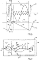
- the curve 54 giving the phase shift ⁇ (axis 52) as a function of time t (axis 51) admits on each modulation period T a linear part 55 corresponding to the desired ramp and a part 56 parasitic due to the rise time.
- the sampling generator 45 proceeds in such a way that the sampling instants t 0 , t 1 .... t 15 are equi-distributed over an acquisition duration D a associated with the linear part 55. No acquisition takes place. on the other hand takes place during a period of non-acquisition D n corresponding to the parasitic part 56.
- a sinusoidal variation of the phase shift ⁇ (axis 53) as a function of time (axis 51) therefore has a curve 57 which admits over each period T a regular part 58 during the duration D a and a parasitic part 59 during the duration D n .
- the regular part 58 is that which would be obtained with a phase shift ⁇ t (except for the sign).
- the form of modulation producing the curve 54 is usually only achievable with phase modulators of the electro-optical type.
- the sampling generator 45 is absent from the processing unit 5 and the DSP 40 is equipped with a phase locked loop (PLL).
- PLL phase locked loop
- the PLL generates sampling instants T k equi-distributed over each period and the DSP 40 performs a usual fast Fourier transform.
- the sampling generator 45 is absent from the processing unit 5 and the DSP 40 is provided with a PLL which generates 2N sampling instants T k equi - distributed over each period.
- the computer 43 stores previously in memory m predetermined functions g j (t), called demodulation functions.
- the functions g j form the dual basis of m harmonic coordinates H l (t) of calculation grouped in a harmonic vector H (t).
- the DSP 40 then evaluates the j-th harmonic component b j of a function f (representative of an electrical signal supplied by the PSD 4) by
- the PSG 3A is equipped with a time stabilization system for phase modulation.
- This system ( Figure 5) includes the beam splitter 27, which sends the control beam 15 to the DSP 40 via a photomultiplier 46.
- the stabilization system also includes a digital-analog converter 44 or DAC (Digital Analogic Converter), which receives control signals from the computer 43 and supplies the amplifier 42 with control voltages (low voltages) U 1 and U 2 respectively intended for modulators 21 and 22.
- DAC Digital Analogic Converter
- the DSP 40 calculates the harmonic coordinates associated with the control beam 15, representative of the modulated incident beam 11, in the fixed harmonic base. It supplies these harmonic coordinates to the computer 43, which determines, from setpoint values, the voltages U 1 and U 2 to be applied to compensate for parasitic phase shifts, due in particular to temperature variations. The computer 43 then supplies these voltages U 1 , U 2 to the amplifier 42 via the DAC 44. Each of these control voltages U 1 and U 2 is then added to the voltage U supplied by the generator. function 41, before amplification by amplifier 42.
- PSG 3B has a single phase modulator.
- PSG 3B includes a polarizing polarizer 20 linearly the incident beam 10 and a coupled modulator 6B comprising a single phase modulator 21 and a coupling system 61 of the partial polarizer type and phase shifter, operating in reflection.
- the phase modulator 21 is interposed between the polarizer 20 and the coupling 61, so that it produces a first modulation of the polarized incident beam 10 and sends it to the coupling system 61, the latter returning the beam incident 10 to the phase modulator 21 which produces a second modulation.
- the 6B coupled modulator includes also a mirror 62 disposed between the polarizer 20 and the modulator 21, which reflects the beam 11 modulated twice to sample 1.
- the polarizer 20 is oriented along the y axis and the modulator 21 is oriented in the xy plane in a direction forming an angle ⁇ 3 with l x axis, ⁇ 3 being equal to 45 °.
- the coupling system 61 is in turn oriented along the x axis, so as to allow a return of the incident beam 10 parallel to the outward journey.
- the mirror 62 advantageously returns the beam 11 along the y axis.
- the modulator 21 is an electro-optical modulator ( Pockels). Such a modulator 21 allows external control phase shift and have a bandwidth exceeding 100 MHz. This bandwidth only depends on the generator signal 41 and amplifier 42.
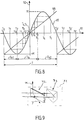
- the phase modulator 21 is a photoelastic modulator. We thus obtain a extended wavelength range and a large window optical. The shape of the phase shift ⁇ (t) is then fixed and it is proportional to sin ⁇ t ( Figure 8).
- the desired harmonics are calculated using the SFFT previously described, for example by a generator sampling and a DSP similar to those of the first embodiment referenced respectively 45 and 40 and the SFFT1 ( Figure 5).
- the PSG 3B modulation matrix W is thus of rank 4, whereas a usual FFT would make this singular matrix.
- the modulator 21 has an amplitude of modulation greater than or equal to ⁇ , so as to make the SFFT1 applicable.
- Figure 8 By adopting a sampling of eight points per period T, equal to 2 ⁇ / ⁇ , we obtain the eight points T 0 -T 7 equi-distributed over the period T (and in a similar way on the following period: T ' 0 -T' 7 ).
- the eight sampling instants t 0 -t 7 (and over the following period t ' o , t' 1 , etc.) are obtained by the formula of SFFT1, and distributed over an acquisition duration D a .
- the additional duration over period T is made up of two durations D n1 and D n2 of non-acquisition.
- the images of the sampling instants t k are then obtained from curve 65 giving the phase shift ⁇ as a function of time t and of curve 66, of the form ⁇ t.
- the images of the instants t k on the curve 65 correspond to the images of the points T k on the curve 66.
- SFFT2 provides another implementation advantageous.
- the PPS has two separate elements 72 and 73 performing respectively the partial polarization functions on the one hand, and phase shift and reflection on the other.
- the partial bias element 72 is advantageously constituted by a stack of air-material blades, for example formed by glass plates successive of index N1. Preferably, it is oriented according to the Brewster angle. This indeed ensures the best tradeoff between partial polarization and total loss intensity, without phase shift.
- the type of materials used and the number of blades are chosen according to the range spectral to cover.
- the element 73 of phase shift and reflection is a prism. An incident beam on this element 73 is thus reflected with a phase shift which depends on the index N2 of the prism, without undergoing partial polarization, nor losing intensity,
- element 73 is a prism right, so that the incident beam is reflected in parallel.
- element 73 is a glass prism of the type marketed under the name C4834, which has indices from 1.68 to 404 nm and 1.64 to 706 nm.
- the number of passages n is chosen according to the range of application in wavelength, and gives the index N1.
- the optimal value of N1 is then 2.6, which can be approached for example with ZnS.
- the plates are then formed for example by the material sold under the name BK7.
- the plates are then for example made of fused silica.
- PSD 4 is based on a state separator polarization ( Figure 4) comprising fixed elements without modulation.
- Figure 4 A variant is to use the reflections of the measurement beam 12 on at least four photodetectors.
- a description of such a PSD can be found in "Arrangement of four photodetectors for measuring the state of polarization of light ", R.M. Azzam, Optics Letters, Flight. 10, pp. 309-311, 1985.
- the PSD 4 includes a frequency bias modulator different from that of PSG 3.
- the ellipsometer then uses a single-channel technique, the basis of harmonics chosen comprising at least sixteen components. he is also possible to use for the PSD a single channel technique or multi-channel involving moving elements.
- one of the PSG 3A, 3B described above can be used as a PSD in the exit arm, associated with any of the PSGs in the entry arm.
- the PSD corresponds in this case to Figures 2 and 7 except that the polarizer 20 is located in the emerging beam 11 instead of incident beam 10.
- the orientation of the optical elements is advantageously the even in PSD and PSG.
- the modulation frequency of the PSD corresponds to 5 times or 1/5 times that ( ⁇ / 2 ⁇ ) of PSG.
- any of PSG 3A, 3B can be used independently as a state detector polarization (measurement of the Stokes vector) in any assembly optical.
- the first level concerns the orientation of the elements optical, determination of the modulation amplitude, and the servo operation.
- one operates from the as follows: we define an absolute angle reference by the orientation of the polarizer 20 of the PSG 3. To do this, we do so that a light linearly polarized in the plane incidence is reflected without cross polarization. So, we uses a polarizer in the incident beam and one, rotated ⁇ / 2 of the first, in the reflected beam, and we turn them together until the beam is completely turned off. The other optical elements are then aligned with respect to this polarizer 20.
- the second level of calibration which is the most important, is the determination of the modulation W and detection A matrices.
- a self-calibration method described below is preferably used. First of all, a set of calibration entities is chosen having known Mueller matrices. One of these Mueller matrices is the identity matrix I 0 (nothing in transmission). Each of the other calibration entities is then successively adopted as sample 1 and ellipsometric measurements are carried out. We thus obtain for each Mueller matrix entity M, the AMW matrix from these measurements. The matrix Al 0 W is also measured. A system of linear equations is then established, which is solved so as to extract the modulation W and detection A matrices.
- the PSD 4 comprising a state separator of polarization not introducing new modulation temporal, four entities are used successively. One of these four entities is the vacuum, the measurement being carried out in transmission without sample. All of the other three entities includes in transmission a linear polarizer at 0 ° and a linear polarizer at 45 °, and in reflection or transmission a partial polarizer and phase shifter with no singular value. This last one can be a quarter wave blade.
- the self-calibration method gives very precise, because it is linked to the self-coherence of the Mueller formalism. It is also easy and quick to enforce.
- the Mueller ellipsometer according to the invention is suitable for both monochromatic and spectroscopic.
Landscapes
- Physics & Mathematics (AREA)
- General Physics & Mathematics (AREA)
- Spectroscopy & Molecular Physics (AREA)
- Chemical & Material Sciences (AREA)
- Nonlinear Science (AREA)
- General Health & Medical Sciences (AREA)
- Analytical Chemistry (AREA)
- Biochemistry (AREA)
- Life Sciences & Earth Sciences (AREA)
- Immunology (AREA)
- Pathology (AREA)
- Engineering & Computer Science (AREA)
- Ceramic Engineering (AREA)
- Crystallography & Structural Chemistry (AREA)
- Health & Medical Sciences (AREA)
- Optics & Photonics (AREA)
- Investigating Or Analysing Materials By Optical Means (AREA)
- Organic Low-Molecular-Weight Compounds And Preparation Thereof (AREA)
Claims (19)
- Optisches Polarisationsmodulationsbauteil, umfassend einen Polarisationsmodulator (6A, 6B), der einen linear polarisierten eintreffenden Lichtstrahl (10) moduliert und einen modulierten Strahl (11) zurücksendet, wobei der Polarisationsmodulator (6A, 6B) ein gekoppelter Phasenmodulator ist, der den eintreffenden Strahl (10) zweimal hintereinander moduliert, wobei sich die beiden Modulationen genau auf derselben Frequenz ù/2o befinden und gekoppelt werden, dadurch gekennzeichnet, dass die Modulationen durch ein System (23, 61, 71) gekoppelt werden, das den Polarisationszustand des Lichtes zwischen den beiden Modulationen verändert.
- Optisches Bauteil nach Anspruch 1, dadurch gekennzeichnet, dass der gekoppelte Modulator (6B) einen Phasenmodulator (21) umfasst, der die beiden aufeinanderfolgenden Modulationen erzeugt, und dass das Kopplungssystem (61, 71) vom Typ Teilpolarisator und Phasenverschieber ist, wobei der Phasenmodulator (21) die erste Modulation erzeugt und den eintreffenden Strahl (10) zu dem Kopplungssystem (61, 71) sendet, wobei das Kopplungssystem (61, 71) den eintreffenden Strahl (10) zu dem Phasenmodulator (21) zurücksendet und der Phasenmodulator (21) die zweite Modulation erzeugt.
- Optisches Bauteil nach Anspruch 2, dadurch gekennzeichnet, dass, da das Licht des eintreffenden Strahls (10) linear entlang einer Polarisationsrichtung (y) polarisiert wird, der Phasenmodulator (21) und das Kopplungssystem (61) 45° bzw. 90° zu der Polarisationsrichtung (y) ausgerichtet sind.
- Optisches Bauteil nach Anspruch 1, dadurch gekennzeichnet, dass der gekoppelte Modulator (6A) zwei Phasenmodulatoren (21, 22) umfasst, die jeweils die beiden selben aufeinanderfolgenden Modulationen erzeugen, wobei die beiden Phasenmodulatoren (21, 22) eine selbe Ausrichtung haben, und dass das Kopplungssystem (23) vom Typ Teilpolarisator und Phasenverschieber ist, wobei das Kopplungssystem (23) zwischen den beiden Phasenmodulatoren (21, 22) angeordnet ist und den eintreffenden Strahl (10) des ersten (21) zu dem zweiten (22) der Phasenmodulatoren zurücksendet.
- Optisches Bauteil nach Anspruch 4, dadurch gekennzeichnet, dass, da das Licht des eintreffenden Strahls (10) linear entlang einer Polarisationsrichtung (y) polarisiert wird, die Phasenmodulatoren (21, 22) einerseits und das Kopplungssystem (23) andererseits jeweils 45° bzw. 90° zu der Polarisationsrichtung (y) ausgerichtet sind.
- Optisches Bauteil nach einem der Ansprüche 1 bis 5, dadurch gekennzeichnet, dass das Kopplungssystem (71) mit Reflexion funktioniert und ein erstes Teilpolarisationselement (72) und ein zweites Phasenverschiebungs- und Reflexionselement (73) umfasst.
- Optisches Bauteil nach Anspruch 6, dadurch gekennzeichnet, dass das erste Element (72) von einer Anhäufung von Luft-Stoff-Schnittstellen im Brewster-Winkel und das zweite Element (73) von einem Prisma gebildet ist.
- Polarimeter, dadurch gekennzeichnet, dass es ein optisches Bauteil nach einem der Ansprüche 1 bis 7 umfaßt.
- Müller-Ellipsometer, das zum Messen eines Musters (1) bestimmt ist, welches durch Koeffizienten einer Müller-Matrix (M) dargestellt ist, umfassend:dadurch gekennzeichnet, dass der Polarisationsmodulator (6A, 6B) in einem optischen Bauteil nach einem der Ansprüche 1 bis 5 eingeschlossen ist, dass die Erfassungsmittel (4) ein Polarimeter umfassen, das Mittel enthält, die es ermöglichen, n gemessene Mengen (I1 - In) zu erzeugen, die die Polarisationszustände des Messstrahls (12) darstellen, und dass die Bearbeitungseinheit (5) Mittel umfasst, die es ermöglichen, durch Fourier-Transformation m Werte für jede der n gemessenen Mengen (I1 - In) mit n x m ≥ 16 und m ≥ 4 zu erzeugen, wodurch es möglich ist, gleichzeitig auf die sechzehn Koeffizienten der Müller-Matrix (M) zuzugreifen.eine Lichtquelle (2), die einen eintreffenden Lichtstrahl (10) entsendet,einen Polarisator (20), der den eintreffenden Strahl (10) linear polarisiert,einen Polarisationsmodulator (6A, 6B), der den eintreffenden Strahl (10) moduliert, wobei das Muster (1) den modulierten eintreffenden Strahl (11) empfängt und einen Messstrahl (12) zurücksendet,Mittel (4) zur Erfassung des Messstrahls (12), die elektrische Signale erzeugen, undeine Bearbeitungseinheit (5), die die elektrischen Signale empfängt, die von den Erfassungsmitteln (4) erzeugt werden,
- Ellipsometer nach Anspruch 9, dadurch gekennzeichnet, dass es die Mittel des Polarimeters ermöglichen, n ≥ 4 gemessene Mengen zu erzeugen, und dass das Polarimeter eine derartige Struktur aufweist, dass es keine neue Zeitmodulation einführt.
- Ellipsometer nach Anspruch 10, dadurch gekennzeichnet, dass es die Mittel des Polarimeters und der Bearbeitungseinheit ermöglichen, n = 4 gemessene Mengen und m = 4 Werte zu erzeugen, und dass das Polarimeter eine Struktur aufweist, die es ermöglicht, die vier Polarisationszustände des Messstrahls (12), die den vier gemessenen Mengen (I1 - In) zugeordnet sind, zu trennen.
- Ellipsometer nach Anspruch 11, dadurch gekennzeichnet, dass, da das optische Bauteil durch einen der Ansprüche 1 bis 5 definiert ist, wobei die Bearbeitungseinheit Mittel umfasst, um vier Werte zu erzeugen, die durch Fourier-Transformation für jede gemessene Menge (I1 - In), die von der Zeit t abhängt, erzeugt wurden, wobei die vier Werte die harmonischen Koordinaten der gemessenen Menge (I1 - In) in der Basis darstellen
cos ωt, sin ωt, cos 2 ωt, sin 2 ωt. - Ellipsometer nach einem der Ansprüche 9 bis 12, dadurch gekennzeichnet, dass die Bearbeitungseinheit Mittel umfasst, die es ermöglichen, die m Werte für jede der n gemessenen Mengen Ih(t) mit Hilfe einer speziellen Fourier-Transformation zu erzeugen, nach der, wenn m harmonische Rechnungskoordinaten Hl(t), die von der Zeit t abhängen, in einem harmonischen Vektor H(t) zusammengefasst werden, wobei das Intervall [0,2/ω] in 2N gleichverteilte Punkte TK unstetig gemacht wird und die gemessene Menge Ih(t) zu Bemusterungszeitpunkten tK berechnet wird, wobei K von 0 bis 2 N-1 variiert, es die Mittel der Bearbeitungseinheit ermöglichen, den j-ten harmonischen Bauteil Bhj der Funktion Ih zu bewerten, wobei j von 1 bis m und h von 1 bis n variiert, und zwar durch:
 wobei die Funktionen gj(t) Demodulationsfunktionen sind, die derart gewählt sind, dass die Demodulationsmatrix D gegeben ist durch
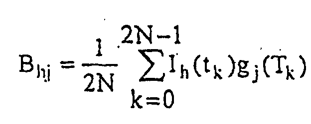 worin l und j, die von 1 bis m variieren, einen Rang höher oder gleich 4 sind.
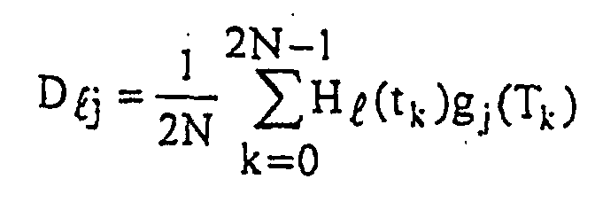
- Ellipsometer nach Anspruch 13, dadurch gekennzeichnet, dass es die Mittel der Bearbeitungseinheit ermöglichen, zwei Phasenmodulationen anzulegen, die eine selbe Phasenverschiebung _(t) aufweisen, wobei
- Ellipsometer nach Anspruch 13, dadurch gekennzeichnet, dass die Mittel der Bearbeitungseinheit derart strukturiert sind, dass tK = TK und dass die Funktionen gj derat sind, dass D die Identitätsmatrix ist.
- Ellipsometer nach einem der Ansprüche 9 bis 15, dadurch gekennzeichnet, dass die Erfassungsmittel (4) der Bearbeitungseinheit (5) an spektroskopische Messungen angepasst sind.
- Verfahren zur Kalibrierung eines Ellipsometers, dadurch gekennzeichnet, dass, für ein Ellipsometer, das durch einen der Ansprüche 9 bis 16 definiert ist, wobei der Polarisator (20) und der Polarisationsmodulator (6A, 6B) einen Erzeuger von Polarisationszuständen (3) darstellen, wobei die Erzeuger von Polarisationszuständen (3) und die Erfassungsmittel (4) jeweils eine Modulationsmatrix (W) und eine Erfassungsmatrix (A) aufweisen,eine Gesamtheit von Kalibriereinheiten gewählt wird, die bekannte Müller-Matrices (M) aufweisen, wobei eine der Einheiten der Identitätsmatrix (Io) entspricht,für jede der Kalibriereinheiten die Einheit als ein Muster (1) in dem Ellipsometer angenommen wird, ein linear mit der Lichtquelle (2) und dem Polarisator (20) polarisierter eintreffender Lichtstrahl (10) entsandt wird, der eintreffende Strahl (10) durch den gekoppelten Modulator (6A, 6B) moduliert wird, der modulierte eintreffende Strahl (11) auf die Einheit (1) entsandt wird und ein Messstrahl (12) zurückgesandt wird, die gemessenen Mengen (I1 - In) durch die Erfassungsmittel (4) und die Werte durch die Bearbeitungseinheit (5) erzeugt werden und ausgehend von diesen Werten, eine Messmatrix (AMW), die ein Produkt aus der Erfassungsmatrix (A), der Müller-Matrix (M) der Einheit und der Modulationsmatrix (W) ist, konstruiert wird,ein System linearer Gleichungen auf Basis der erzeugten Messmatrices (AMW) erstellt wird, unddas System derart gelöst wird, dass die Modulationsmatrix (W) und die Erfassungsmatrix (A) entnommen werden.
- Kalibrierverfahren nach Anspruch 17, dadurch gekennzeichnet, dass eine Gesamtheit von Einheiten gewählt wird, umfassend:einen Linearpolarisator mit 0° Übertragung,einen Linearpolarisator mit 45° Übertragung undeinen Teilpolarisator und Phasenverschieber ohne Einzelwerte.
- Ellipsometrisches Messverfahren, das für die Messung eines Musters (1) bestimmt ist, das durch Koeffizienten einer Müller-Matrix (M) dargestellt ist, bei demdadurch gekennzeichnet, dassein linear polarisierter eintreffender Lichtstrahl (10) entsandt wird,der eintreffende Strahl (10) durch einen Polarisationsmodulator (6A, 6B) moduliert wird,der modulierte eintreffende Strahl (11) auf das Muster (1) entsandt und ein Messstrahl (12) zurückgesandt wird,der Messstrahl (12) erfasst wird und elektrische Signale durch Erfassungsmittel (4) erzeugt werden, unddie elektrischen Signale an eine Bearbeitungseinheit (5) übertragen werden,am eintreffenden Strahl (10) mit Hilfe des Polarisationsmodulators (6A, 6B) zwei aufeinanderfolgende Phasenmodulationen vorgenommen werden, wobei sich die beiden Modulationen genau auf derselben Frequenz ω/2
Applications Claiming Priority (3)
| Application Number | Priority Date | Filing Date | Title |
|---|---|---|---|
| FR9613081 | 1996-10-25 | ||
| FR9613081A FR2755254B1 (fr) | 1996-10-25 | 1996-10-25 | Composant optique de modulation, polarimetre et ellipsometre de mueller comprenant un tel composant optique, procede de calibrage de cet ellipsometre et procede de mesure ellipsometrique |
| PCT/FR1997/001849 WO1998019142A1 (fr) | 1996-10-25 | 1997-10-16 | Composant optique de modulation de polarisation, et son utilisation dans un polarimetre ou dans un ellipsometre |
Publications (2)
| Publication Number | Publication Date |
|---|---|
| EP0870180A1 EP0870180A1 (de) | 1998-10-14 |
| EP0870180B1 true EP0870180B1 (de) | 2001-12-05 |
Family
ID=9497060
Family Applications (1)
| Application Number | Title | Priority Date | Filing Date |
|---|---|---|---|
| EP97910494A Expired - Lifetime EP0870180B1 (de) | 1996-10-25 | 1997-10-16 | Optisches bauelement zur polarisationsmodulation, und dessen verwendung in einem polarimeter oder ellipsometer |
Country Status (8)
| Country | Link |
|---|---|
| US (1) | US6175412B1 (de) |
| EP (1) | EP0870180B1 (de) |
| JP (1) | JP2000502461A (de) |
| KR (1) | KR19990076790A (de) |
| AT (1) | ATE210284T1 (de) |
| DE (1) | DE69708839T2 (de) |
| FR (1) | FR2755254B1 (de) |
| WO (1) | WO1998019142A1 (de) |
Families Citing this family (33)
| Publication number | Priority date | Publication date | Assignee | Title |
|---|---|---|---|---|
| FR2779825B1 (fr) * | 1998-06-16 | 2000-09-01 | Centre Nat Rech Scient | Procede et dispositif de commande de la fabrication d'un composant en couche mince a partir d'une dissociation de gaz |
| HU226937B1 (en) * | 2000-11-17 | 2010-03-29 | Mta Szegedi Biolog Koezpont | Method and apparatus for determining polarization amount of material by a laser scanning microscope |
| US6836327B1 (en) * | 2001-03-16 | 2004-12-28 | General Photonics Corporation | In-line optical polarimeter based on integration of free-space optical elements |
| EP1446641A4 (de) | 2001-10-15 | 2009-01-07 | Xiangdong Zhu | Verfahren und vorrichtungen zur messung des brechnungsindex und optischer absorptionsdifferenzen |
| EP1411333B1 (de) * | 2002-10-15 | 2006-03-08 | Centre National De La Recherche Scientifique (Cnrs) | Auf Flüssigkristallen basierendes polarimetrisches System, Verfahren zu seiner Kalibrierung, und polarimetrisches Messverfahren |
| US7495764B1 (en) | 2002-11-07 | 2009-02-24 | The United States Of America As Represented By The Secretary Of The Army | Coherent radar and ladar polarimeter |
| JP4080508B2 (ja) * | 2003-03-28 | 2008-04-23 | シチズンホールディングス株式会社 | 旋光度測定装置 |
| KR100605507B1 (ko) * | 2004-11-08 | 2006-07-28 | 삼성전자주식회사 | 편광 상태 측정 장치 및 그 측정 방법 |
| US7375799B2 (en) * | 2005-02-25 | 2008-05-20 | Asml Netherlands B.V. | Lithographic apparatus |
| JP4739411B2 (ja) * | 2005-06-13 | 2011-08-03 | エーエスエムエル ネザーランズ ビー.ブイ. | リソグラフィ投影システムおよび投影レンズ偏光センサ |
| ATE385736T1 (de) * | 2005-07-01 | 2008-03-15 | Ecole Polytech | Polarimetrisch elektronisches abbildungssystem für eine kolposkopische vorrichtung |
| KR100732118B1 (ko) * | 2005-11-24 | 2007-06-25 | 안일신 | 회전 보상기형 외축 타원 해석기 |
| US7796257B2 (en) * | 2006-01-13 | 2010-09-14 | National University Corporation Tokyo University Of Agriculture And Technology | Measuring apparatus, measuring method, and characteristic measurement unit |
| EP1811287A1 (de) * | 2006-01-20 | 2007-07-25 | Ecole Polytechnique | Polarimetrisches Ramansystem und Verfahren zur Analyse einer Probe |
| JPWO2007111159A1 (ja) * | 2006-03-20 | 2009-08-13 | 国立大学法人東京農工大学 | 光学特性計測装置及び光学特性計測方法、並びに、光学特性計測ユニット |
| US7557918B1 (en) | 2006-04-05 | 2009-07-07 | Itt Manufacturing Enterprises, Inc. | Spectral polarimetric image detection and analysis methods and apparatus |
| US7928390B1 (en) * | 2007-09-06 | 2011-04-19 | Kla-Tencor Corporation | Infrared metrology |
| US7945130B2 (en) * | 2007-11-15 | 2011-05-17 | General Photonics Corporation | Mode scrambling apparatus for multimode fiber |
| US20090141274A1 (en) * | 2007-11-29 | 2009-06-04 | Bogdan Szafraniec | Polarization Dependent Loss Analyzer |
| FR2937732B1 (fr) | 2008-10-29 | 2010-12-31 | Horiba Jobin Yvon Sas | Dispositif et procede de mesures polarimetriques spectroscopiques dans le domaine visible et proche infrarouge |
| JP2010145332A (ja) * | 2008-12-22 | 2010-07-01 | Tokyo Univ Of Agriculture & Technology | 光学特性計測装置、光学特性計測方法、および光学特性計測装置の校正方法 |
| US8780433B2 (en) | 2011-09-28 | 2014-07-15 | General Photonics Corporation | Polarization scrambling based on cascaded optical polarization devices having modulated optical retardation |
| FR3018914B1 (fr) | 2014-03-18 | 2016-05-06 | Centre Nat Rech Scient | Dispositif et methode de caracterisation polarimetrique deportee |
| WO2016057464A1 (en) | 2014-10-06 | 2016-04-14 | Applied Photophysics, Inc. | Calibration device and uses thereof |
| DE102016117326A1 (de) | 2016-09-06 | 2018-03-08 | Novoptel GmbH | Polarimeter für polarisationsmodulierte Signale |
| JP6351893B1 (ja) * | 2018-02-26 | 2018-07-04 | 日本分光株式会社 | 位相差制御装置 |
| CN108871579B (zh) * | 2018-04-27 | 2020-11-13 | 北京理工大学 | 一种偏振成像系统的标定方法 |
| JPWO2020202695A1 (de) * | 2019-04-03 | 2020-10-08 | ||
| CN110261317B (zh) * | 2019-06-17 | 2021-11-16 | 西安理工大学 | 一种Mueller矩阵光谱的测量系统及方法 |
| CN111307722B (zh) * | 2019-11-29 | 2021-04-16 | 北京理工大学 | 一种多功能Stokes-Mueller矩阵成像偏振仪的标定方法 |
| US12405223B2 (en) | 2020-10-30 | 2025-09-02 | The Board Of Trustees Of The Leland Stanford Junior University | Matrix-based characterization and measurements for semiconductor thin-film material |
| CN115575329B (zh) * | 2022-09-27 | 2026-03-17 | 中北大学 | 一种基于双弹光级联差频调制的全范围椭偏测量装置 |
| US12584744B2 (en) * | 2023-12-21 | 2026-03-24 | Northrop Grumman Systems Corporation | Cascaded optical modulation system |
Family Cites Families (2)
| Publication number | Priority date | Publication date | Assignee | Title |
|---|---|---|---|---|
| US4306809A (en) * | 1979-03-26 | 1981-12-22 | The Board Of Regents Of The University Of Nebraska | Polarimeter |
| US5956147A (en) * | 1997-06-13 | 1999-09-21 | Lockheed Martin Energy Research Corporation | Two modulator generalized ellipsometer for complete mueller matrix measurement |
-
1996
- 1996-10-25 FR FR9613081A patent/FR2755254B1/fr not_active Expired - Fee Related
-
1997
- 1997-10-16 DE DE69708839T patent/DE69708839T2/de not_active Expired - Fee Related
- 1997-10-16 EP EP97910494A patent/EP0870180B1/de not_active Expired - Lifetime
- 1997-10-16 US US09/091,400 patent/US6175412B1/en not_active Expired - Fee Related
- 1997-10-16 WO PCT/FR1997/001849 patent/WO1998019142A1/fr not_active Ceased
- 1997-10-16 KR KR1019980704915A patent/KR19990076790A/ko not_active Withdrawn
- 1997-10-16 AT AT97910494T patent/ATE210284T1/de not_active IP Right Cessation
- 1997-10-16 JP JP10520100A patent/JP2000502461A/ja not_active Ceased
Also Published As
| Publication number | Publication date |
|---|---|
| KR19990076790A (ko) | 1999-10-15 |
| US6175412B1 (en) | 2001-01-16 |
| WO1998019142A1 (fr) | 1998-05-07 |
| FR2755254B1 (fr) | 1999-01-15 |
| ATE210284T1 (de) | 2001-12-15 |
| DE69708839D1 (de) | 2002-01-17 |
| FR2755254A1 (fr) | 1998-04-30 |
| JP2000502461A (ja) | 2000-02-29 |
| EP0870180A1 (de) | 1998-10-14 |
| DE69708839T2 (de) | 2002-10-31 |
Similar Documents
| Publication | Publication Date | Title |
|---|---|---|
| EP0870180A1 (de) | Optisches bauelement zur polarisationsmodulation, und dessen vewendung in einem polarimeter oder ellipsometer | |
| EP3765835B1 (de) | Momentanellipsometer oder streumessgerät und zugehöriges messverfahren | |
| EP3488505B1 (de) | Verfahren und system zur akustischen resonanzspektroskopie | |
| EP0663590B1 (de) | Moduliertes Spektralellipsometer | |
| EP3899497B1 (de) | Laservorrichtung zur polarisationsinterferometrie | |
| EP3394560A1 (de) | Vorrichtung und verfahren zur messung der höhe in gegenwart von dünnschichten | |
| FR2937732A1 (fr) | Dispositif et procede de mesures polarimetriques spectroscopiques dans le domaine visible et proche infrarouge | |
| EP0558863B1 (de) | Infrarot-Elliposmeter | |
| EP0027763B1 (de) | Verfahren und Apparat zur Abstandsmessung durch Laserinterferometrie mit zwei Wellenlängen | |
| EP3019841B1 (de) | Vorrichtung zur kompensation des drifts einer phasenverschiebung einer vorrichtung zur modulierung des polarisationszustandes eines lichtstrahls | |
| EP0942261B1 (de) | Verfahren und Vorrichtung zur Messung von Strukturtiefen einer Probenoberfläche | |
| FR2595471A1 (fr) | Dispositif d'ellipsometrie spectroscopique a fibres optiques | |
| FR2976663A1 (fr) | Dispositif et procede de caracterisation d'un faisceau de lumiere. | |
| EP4182675B1 (de) | Vorrichtung zur polarimetrischen charakterisierung der anisotropie eines mediums und entsprechendes abbildungssystem | |
| EP0933629A1 (de) | Interferenzverfahren und Vorrichtung zum Messen der Phasenverschiebung zwischen zweier von einer einzelnen polarisierten Quelle ausgehender Lichtstrahlen, sowie deren Anwendung in der Refraktometrie | |
| FR3132947A1 (fr) | Systèmes et procédés d’analyse de la qualité de surface d’une lame à faces parallèles | |
| EP1674878B1 (de) | Elektrooptische Sonde zur Messung elektrischer oder elektromagnetischer Felder mit einer Steuerung der Wellenlänge des Betriebspunkts | |
| EP4078217A1 (de) | Lidar-system mit zwei diffraktiven komponenten | |
| FR3164017A1 (fr) | Dispositif de mesure polarimétrique par interférométrie spectrale de grandeurs anisotropiques d’un milieu, et procédé de mesure correspondant | |
| EP1162473B1 (de) | Laufzeitdifferenzmesser und Peilanordnung | |
| FR3164289A1 (fr) | Appareil optique d’analyse de surfaces à l’aide de lumières réfléchies par processus optiques linéaire et non linéaire | |
| EP0635730A1 (de) | Geschwindigkeitsmesser mit dynamischen Hologramm |
Legal Events
| Date | Code | Title | Description |
|---|---|---|---|
| PUAI | Public reference made under article 153(3) epc to a published international application that has entered the european phase |
Free format text: ORIGINAL CODE: 0009012 |
|
| AK | Designated contracting states |
Kind code of ref document: A1 Designated state(s): AT BE CH DE DK ES FI FR GB GR IE IT LI LU MC NL PT SE |
|
| 17P | Request for examination filed |
Effective date: 19981109 |
|
| 17Q | First examination report despatched |
Effective date: 20000516 |
|
| GRAG | Despatch of communication of intention to grant |
Free format text: ORIGINAL CODE: EPIDOS AGRA |
|
| GRAG | Despatch of communication of intention to grant |
Free format text: ORIGINAL CODE: EPIDOS AGRA |
|
| GRAH | Despatch of communication of intention to grant a patent |
Free format text: ORIGINAL CODE: EPIDOS IGRA |
|
| GRAH | Despatch of communication of intention to grant a patent |
Free format text: ORIGINAL CODE: EPIDOS IGRA |
|
| GRAA | (expected) grant |
Free format text: ORIGINAL CODE: 0009210 |
|
| AK | Designated contracting states |
Kind code of ref document: B1 Designated state(s): AT BE CH DE DK ES FI FR GB GR IE IT LI LU MC NL PT SE |
|
| PG25 | Lapsed in a contracting state [announced via postgrant information from national office to epo] |
Ref country code: NL Free format text: LAPSE BECAUSE OF FAILURE TO SUBMIT A TRANSLATION OF THE DESCRIPTION OR TO PAY THE FEE WITHIN THE PRESCRIBED TIME-LIMIT Effective date: 20011205 Ref country code: IT Free format text: LAPSE BECAUSE OF FAILURE TO SUBMIT A TRANSLATION OF THE DESCRIPTION OR TO PAY THE FEE WITHIN THE PRE;WARNING: LAPSES OF ITALIAN PATENTS WITH EFFECTIVE DATE BEFORE 2007 MAY HAVE OCCURRED AT ANY TIME BEFORE 2007. THE CORRECT EFFECTIVE DATE MAY BE DIFFERENT FROM THE ONE RECORDED.SCRIBED TIME-LIMIT Effective date: 20011205 Ref country code: IE Free format text: LAPSE BECAUSE OF FAILURE TO SUBMIT A TRANSLATION OF THE DESCRIPTION OR TO PAY THE FEE WITHIN THE PRESCRIBED TIME-LIMIT Effective date: 20011205 Ref country code: GR Free format text: LAPSE BECAUSE OF FAILURE TO SUBMIT A TRANSLATION OF THE DESCRIPTION OR TO PAY THE FEE WITHIN THE PRESCRIBED TIME-LIMIT Effective date: 20011205 Ref country code: FI Free format text: LAPSE BECAUSE OF FAILURE TO SUBMIT A TRANSLATION OF THE DESCRIPTION OR TO PAY THE FEE WITHIN THE PRESCRIBED TIME-LIMIT Effective date: 20011205 Ref country code: AT Free format text: LAPSE BECAUSE OF FAILURE TO SUBMIT A TRANSLATION OF THE DESCRIPTION OR TO PAY THE FEE WITHIN THE PRESCRIBED TIME-LIMIT Effective date: 20011205 |
|
| REF | Corresponds to: |
Ref document number: 210284 Country of ref document: AT Date of ref document: 20011215 Kind code of ref document: T |
|
| REG | Reference to a national code |
Ref country code: CH Ref legal event code: NV Representative=s name: KIRKER & CIE SA Ref country code: CH Ref legal event code: EP |
|
| REG | Reference to a national code |
Ref country code: GB Ref legal event code: IF02 |
|
| REG | Reference to a national code |
Ref country code: IE Ref legal event code: FG4D Free format text: FRENCH |
|
| REF | Corresponds to: |
Ref document number: 69708839 Country of ref document: DE Date of ref document: 20020117 |
|
| PG25 | Lapsed in a contracting state [announced via postgrant information from national office to epo] |
Ref country code: SE Free format text: LAPSE BECAUSE OF FAILURE TO SUBMIT A TRANSLATION OF THE DESCRIPTION OR TO PAY THE FEE WITHIN THE PRESCRIBED TIME-LIMIT Effective date: 20020305 Ref country code: PT Free format text: LAPSE BECAUSE OF FAILURE TO SUBMIT A TRANSLATION OF THE DESCRIPTION OR TO PAY THE FEE WITHIN THE PRESCRIBED TIME-LIMIT Effective date: 20020305 Ref country code: DK Free format text: LAPSE BECAUSE OF FAILURE TO SUBMIT A TRANSLATION OF THE DESCRIPTION OR TO PAY THE FEE WITHIN THE PRESCRIBED TIME-LIMIT Effective date: 20020305 |
|
| GBT | Gb: translation of ep patent filed (gb section 77(6)(a)/1977) |
Effective date: 20020207 |
|
| NLV1 | Nl: lapsed or annulled due to failure to fulfill the requirements of art. 29p and 29m of the patents act | ||
| PG25 | Lapsed in a contracting state [announced via postgrant information from national office to epo] |
Ref country code: ES Free format text: LAPSE BECAUSE OF FAILURE TO SUBMIT A TRANSLATION OF THE DESCRIPTION OR TO PAY THE FEE WITHIN THE PRESCRIBED TIME-LIMIT Effective date: 20020627 |
|
| REG | Reference to a national code |
Ref country code: IE Ref legal event code: FD4D |
|
| PLBE | No opposition filed within time limit |
Free format text: ORIGINAL CODE: 0009261 |
|
| STAA | Information on the status of an ep patent application or granted ep patent |
Free format text: STATUS: NO OPPOSITION FILED WITHIN TIME LIMIT |
|
| PG25 | Lapsed in a contracting state [announced via postgrant information from national office to epo] |
Ref country code: LU Free format text: LAPSE BECAUSE OF NON-PAYMENT OF DUE FEES Effective date: 20021016 |
|
| PG25 | Lapsed in a contracting state [announced via postgrant information from national office to epo] |
Ref country code: BE Free format text: LAPSE BECAUSE OF NON-PAYMENT OF DUE FEES Effective date: 20021031 |
|
| 26N | No opposition filed | ||
| BERE | Be: lapsed |
Owner name: CENTRE NATIONAL DE LA *RECHERCHE SCIENTIFIQUE Effective date: 20021031 |
|
| PG25 | Lapsed in a contracting state [announced via postgrant information from national office to epo] |
Ref country code: MC Free format text: LAPSE BECAUSE OF NON-PAYMENT OF DUE FEES Effective date: 20030501 |
|
| PGFP | Annual fee paid to national office [announced via postgrant information from national office to epo] |
Ref country code: FR Payment date: 20060911 Year of fee payment: 10 |
|
| PGFP | Annual fee paid to national office [announced via postgrant information from national office to epo] |
Ref country code: GB Payment date: 20060926 Year of fee payment: 10 Ref country code: CH Payment date: 20060926 Year of fee payment: 10 |
|
| PGFP | Annual fee paid to national office [announced via postgrant information from national office to epo] |
Ref country code: DE Payment date: 20060928 Year of fee payment: 10 |
|
| GBPC | Gb: european patent ceased through non-payment of renewal fee |
Effective date: 20071016 |
|
| REG | Reference to a national code |
Ref country code: CH Ref legal event code: PL |
|
| PG25 | Lapsed in a contracting state [announced via postgrant information from national office to epo] |
Ref country code: LI Free format text: LAPSE BECAUSE OF NON-PAYMENT OF DUE FEES Effective date: 20071031 Ref country code: DE Free format text: LAPSE BECAUSE OF NON-PAYMENT OF DUE FEES Effective date: 20080501 Ref country code: CH Free format text: LAPSE BECAUSE OF NON-PAYMENT OF DUE FEES Effective date: 20071031 |
|
| REG | Reference to a national code |
Ref country code: FR Ref legal event code: ST Effective date: 20080630 |
|
| PG25 | Lapsed in a contracting state [announced via postgrant information from national office to epo] |
Ref country code: GB Free format text: LAPSE BECAUSE OF NON-PAYMENT OF DUE FEES Effective date: 20071016 |
|
| PG25 | Lapsed in a contracting state [announced via postgrant information from national office to epo] |
Ref country code: FR Free format text: LAPSE BECAUSE OF NON-PAYMENT OF DUE FEES Effective date: 20071031 |