EP0870610A1 - Bahneinzugsvorrichtung für Rotationsdruckmaschinen - Google Patents
Bahneinzugsvorrichtung für Rotationsdruckmaschinen Download PDFInfo
- Publication number
- EP0870610A1 EP0870610A1 EP98101029A EP98101029A EP0870610A1 EP 0870610 A1 EP0870610 A1 EP 0870610A1 EP 98101029 A EP98101029 A EP 98101029A EP 98101029 A EP98101029 A EP 98101029A EP 0870610 A1 EP0870610 A1 EP 0870610A1
- Authority
- EP
- European Patent Office
- Prior art keywords
- material webs
- rotationally symmetrical
- pulling material
- feed element
- guide
- Prior art date
- Legal status (The legal status is an assumption and is not a legal conclusion. Google has not performed a legal analysis and makes no representation as to the accuracy of the status listed.)
- Granted
Links
- 239000000463 material Substances 0.000 claims abstract description 24
- 238000000576 coating method Methods 0.000 claims abstract description 10
- 239000011248 coating agent Substances 0.000 claims abstract description 8
- 239000004809 Teflon Substances 0.000 claims description 12
- 229920006362 Teflon® Polymers 0.000 claims description 12
- 239000004033 plastic Substances 0.000 claims description 8
- 239000002131 composite material Substances 0.000 claims description 4
- 238000001035 drying Methods 0.000 claims 1
- 230000006698 induction Effects 0.000 abstract 1
- XAGFODPZIPBFFR-UHFFFAOYSA-N aluminium Chemical compound [Al] XAGFODPZIPBFFR-UHFFFAOYSA-N 0.000 description 1
- 229910052782 aluminium Inorganic materials 0.000 description 1
- 238000010276 construction Methods 0.000 description 1
- 238000007688 edging Methods 0.000 description 1
- 239000002783 friction material Substances 0.000 description 1
- 238000007373 indentation Methods 0.000 description 1
- 238000009413 insulation Methods 0.000 description 1
- 230000037361 pathway Effects 0.000 description 1
- 230000002093 peripheral effect Effects 0.000 description 1
- 230000000284 resting effect Effects 0.000 description 1
- 230000001960 triggered effect Effects 0.000 description 1
Images



Classifications
-
- B—PERFORMING OPERATIONS; TRANSPORTING
- B41—PRINTING; LINING MACHINES; TYPEWRITERS; STAMPS
- B41F—PRINTING MACHINES OR PRESSES
- B41F13/00—Common details of rotary presses or machines
- B41F13/02—Conveying or guiding webs through presses or machines
- B41F13/03—Threading webs into printing machines
Definitions
- the invention relates to a web feeding device for rotary printing machines, which one or more material webs through all components of a Rotary printing machine leads.
- US 4,987,830 discloses a web feeding device for rotary printing presses. At this device is a plurality of lined up guide rails along the arranged different pathways. There is a linear element in the guide rails recorded, which can be guided along a predetermined path. At the A linear element has a lever attached to it on its side facing the web Snap lock is provided with which a new thread to be threaded into the lever can be hung and pulled through the machine. The Linear element is arranged by means of a plurality of along the guide rails Drive stations moved. The length of the linear element is chosen so that this The distance between two neighboring drive stations just exceeds.
- JP Hei 2-265 848 relates to an apparatus for feeding the paper for one Rotary printing press.
- the web to be introduced is from the Paper roll storage over the printing units to the folder.
- a Feed element for inserting the paper web is designed in the form of a band and comprises regularly arranged openings or elevations on at least one side. The Openings can also completely penetrate the band-shaped feed element.
- At the band-shaped feed element is also a receiving section for the fastening and threading the beginning of the web.
- One of a variety of Existing drive system engages in the openings or elevations of the a band-shaped feed element to guide it through the rotation.
- the invention has for its object a web feed device such to further develop that as low-friction as possible, in all entry paths possible Movement of the web is guaranteed, with the retraction of the web through all Printing machine components should be done without manual intervention.
- the advantages associated with the solution according to the invention are diverse in nature. Thanks to the extremely low-friction feed element, the Feed element through the guide along the feed path for the respective Material web.
- the feed element is also guided by up to 300 ° warm dryer possible without affecting the guidance of the The rotation would come at the beginning of the path.
- the solution according to the invention also enables easier passage of switches to follow other predeterminable path paths.
- the Retractable element have rotationally symmetrical bodies. It can be Balls or pens or the like.
- the arrangement of the Rotationally symmetrical bodies on the feed element are openings for receiving them the rotationally symmetrical body was added.
- the openings in the feed element are lined with low-friction materials to make the movement of the To allow rotationally symmetrical body in the openings of the feed element.
- the openings can be coated with a Teflon coating, for example Teflon linings.
- plastic cages or Be ball cages in which the rotationally symmetrical body then run and be held in the feed element.
- the Contact surfaces of the guide which touch the rotationally symmetrical body, with a provided with a friction-reducing coating.
- the feed element can be designed as a composite material body, which one has a multilayer structure.
- a low-friction layer such as Teflon be.
- Fig. 1 shows a front region of the feed element, which is partially from a guide is enclosed.
- the openings 3 are regularly spaced apart and are used to hold individual rotationally symmetrical bodies, for example balls. In addition to balls, pins or the like would also be conceivable, which in the openings 3 of the Einzugsiatas 2 are inserted.
- the feed element 2 is located on its front area 4 provided with a widening at which the start of a path to be threaded Material web is attachable; the manner of attachment is not closer here received.
- the guide 1 is both provided with a cross section 10 which is rotationally symmetrical Body 5 pass, as well as with a slit-shaped, longitudinally extending opening 9, in which is the intake element 2 is essentially taken up.
- Intervene drive elements 7 which are accommodated on drives 12 shown in FIG. 2.
- the drive elements 7 are designed in Fig. 1 as a cylindrical body, on the circumference several recesses 8 are located, the rotationally symmetrical body 5 of the Grip the feed element 2 and, during their rotation, advance the feed element 2 cause.
- the drives 12 of the drive stations can be electric motors, pneumatic drives or be hydraulic drives; they are arranged along the feed path and ensure that uniform feed of the feed element 2 by the rotation.
- this can on the top and the underside with a coating 11 made of a Teflon layer 16.1 or 16.2 be. As a result, the drive power required on the drives 12 can be reduced are and an equalization of the feed of the feed element 2 can be achieved.
- Fig. 3 shows a deflection of the guide 1. Thanks to the distance of the rotationally symmetrical Body 5 in the feed element 2 is also capable of this extreme deflection angle, as in FIG. 3 shown, happen without the feed element 2 abuts the guide 1; thanks to his Flexibility is capable of adapting itself to every curve, no matter how sharp Widening 4 recorded the beginning of a web of material through the machine, also to lead the turning bar superstructure, in which strong deflections of the web occur can.
- the feed element 2 can, for example, be made of plastic 14, in which Openings 3 balls 5 are embedded. Both the top and bottom of the Feed elements 2 are provided with a friction-reducing coating 16.1 or 16.2 provided how the wall of the openings 3 can be coated. Alternatively, you can the rotationally symmetrical bodies 5 can also be fixed in ball cages 15; at the multilayer composite structure of a feed element 2 are the rotationally symmetrical Body 5 also embedded in openings 3 in the feed element 2. One or both sides several tensile layers 16. 2 are friction-reducing Teflon coatings 16.1 and 16.2 applied. Depending on the structure of the network 16, the number of intended layers vary. Furthermore, the rotationally symmetrical bodies 5 be surrounded by Teflon bezels 16 of the feed element 2.
- Fig. 5 shows an exemplary selected path guide path along the one according to the Fig. 1 - 4 designed feed element 2 is guided by the rotation.
- the drive stations A - H each include a drive 12, the one Drive element 7 drives.
- Each of the drive stations A - H is a button or a pair of switches 19, 20 assigned by which, triggered by the pull-in element 2 itself, the respective Drive station switched on, or the previous one of the drive stations A - H along the Path paths can be switched off again.
- the distance between neighboring ones Drive stations 12, for example A and B, are chosen to be somewhat smaller than the length of the Feed element 2.
- a switch 22 path paths merge.
- the switch 22 itself is by a Piston / cylinder unit 21 or the like moves. Thanks to its low-friction design, what the storage of the rotationally symmetrical body 5, as well as their Concerning guide cross section 10, the feed element 2 can extreme deflections, as here shown in Fig. 3, complete without resting on the inside of the guide 1 or to grind and thereby stop the material web from entering the rotation.
- FIG. 6 7 show a switch 22 integrated in the web feed path according to FIG. 5 in its different positions.
- the switch 22 itself has an actuator 21, which will not be discussed in more detail below.
- On a slide guide 23 is one Base plate 24 slidably received by the actuator 21.
- On the sliding Base plate 24 are a passage element 28 of the guide 1 and a deflection element 29 the guide 1 attached.
- a feed element that has arrived at the end of the guide path 25 2 runs in the setting state of the switch 22 shown in FIG. 6 into the deflection element 29, i. e. whose slot 9 with a guide cross-section 10 to in the further guide path 27 through the Rotation to be promoted. This is done by means of the spaced apart in FIG. 5 Drive stations A - H shown. In the state of the switch 22 shown in FIG. 6, this remains Passage element 28 inactive, the continuation 26 of the guide path 25 from the feed line the feed element 2 cut off.
- Fig. 7 shows the other position of the switch 22, in which the base plate 24 through Actuator 21 was moved so that a continuous passage of the Intake element 2 from the guide path 25 via the passage element 28 into the continuation 26 of the guide path 25 takes place.
- the one attached to the base plate 24 remains Distraction 29 and the further guide path 27 empty.
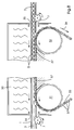
- Fig. 8 finally shows a feed element 2, which a dryer area using a passes below the conveyor chain attacking the web feed element.
- each Drive elements 7 are provided, as have already been described above.
- the guide 1 which is open at the bottom in the area of the dryer 30, is a rotating one Conveyor chain 33 is provided, which rotates around sprockets 31, 32 and through this in Web conveying direction is driven according to the arrows.
- the feed of the Einzugsiatas 2 and the conveyor chain 33 are clocked so that the individual Chain links 37 of the chain 33 each have a rotationally symmetrical body 5 on Support feed element 2.
- the balls 5 shown here lie on the individual Chain links 37 and are fed through along the chain path 36 by their advance promoted the area of the dryer 30.
- the respectively before and after the dryer 30 Arranged drive elements 7 take over the promotion of the feed element 2 in the already described in Figs. 1-5 and 5 by the recesses 8 the overlap rotationally symmetrical body 5 from above.
- the revolving conveyor chain 33 is a standard part and therefore inexpensive; to reach under the Retraction element 2 remains in the area of the guide 1 only the underside of the guide open, so that the chain links 37 engage under the rotationally symmetrical body 5.
- FIGS. 9, 10 show a further embodiment of a drive station 7 for the Feed element 2 shown.
- the drive element 7 comprises two friction rollers 46, 47 arranged within a box 48 which ring around their respective ones Axes are driven analogously to the manner shown in Fig. 2.
- the friction rollers 46, 47 the retraction element 2 provided with rotationally symmetrical bodies 5 between to jam, the rotation of the friction rollers 46, 47 the feed of the Feed element 2 causes.
- Friction rollers 46, 47 provided a recess 49, which the passage of the rotationally symmetrical body 5 between the friction rollers 46, 47 during the advance of the Einzugsiatas 2 allows.
Landscapes
- Engineering & Computer Science (AREA)
- Mechanical Engineering (AREA)
- Registering, Tensioning, Guiding Webs, And Rollers Therefor (AREA)
- Replacement Of Web Rolls (AREA)
- Advancing Webs (AREA)
- Handling Of Sheets (AREA)
Abstract
Description
- Fig. 1
- einen vorderen Bereich des Einzugselementes, teilweise von einer Führung umschlossen,
- Fig. 2
- eine Antriebsstation für das Einzugselement,
- Fig. 3
- eine Umlenkung der Führung,
- Fig. 4
- mehrere Varianten zur Aufnahme der rotationssymmetrischen Körper im Einzugselement,
- Fig. 5
- einen beispielhaft ausgewählten Bahneinführungspfad,
- Fig. 6,7
- eine Weiche für das Einzugselement in unterschiedlichen Positionen und
- Fig. 8
- ein Einzugselement, welches eine Trocknerbereich mit Hilfe einer unterhalb des Bahneinzugselementes angreifenden Förderkette passiert, und die
- Fig. 9,10
- zeigen in schematischer Weise in perspektivischer Darstellung die Ausführung einer Antriebsstation für das erfindungsgemäße Einzugselement.
- 1
- Führung
- 2
- Einzugselement
- 3
- Öffnung
- 4
- Verbreiterung
- 5
- Kugel
- 6
- Eingriffsöffnung
- 7
- Antriebselement
- 8
- Ausnehmung
- 9
- Schlitz
- 10
- Querschnitt
- 11
- Beschichtung
- 12
- Antrieb
- 13
- Achse
- 14
- Kunststoff
- 15
- Kugelkäfige
- 16
- Verbundaufbau
- 16.1
- Teflonschicht
- 16.2
- zugfeste Schicht
- 16.3
- Teflonschicht
- 17
- Tefloneinfassung
- 18
- Kunststoffkäfige
- 19
- erster Steuerschalter
- 20
- zweiter Steuerschalter
- 21
- Weichenantrieb
- 22
- Weiche
- 23
- Kulissenführung
- 24
- Grundplatte
- 25
- Führungspfad
- 26
- Fortsetzung v. Führungspfad
- 27
- weitere Führungspfad
- 28
- Durchgangselement
- 29
- Ablenkung
- 30
- Trockner
- 31
- Kettenrad
- 32
- Kettenrad
- 33
- Kette
- 34
- Öffnung
- 35
- Öffnung
- 36
- Kettenpfad
- 37
- Kettenglied
- 46
- Reibrolle
- 47
- Reibrolle
- 48
- Kasten
- 49
- Ausnehmung
- A - H
- Antriebsstationen
Claims (16)
- Vorrichtung zum Einziehen von Materialbahnen in Rotationsdruckmaschinen mit einem flexiblen, endlichen Einzugselement, dessen Länge etwas größer ist als der Abstand zwischen benachbarten Antriebselementen ist,
dadurch gekennzeichnet,
daß in das flexible Einzugselement (2) rotationssymmetrische Körper (5) eingelassen sind, die dieses führen und dessen Reibung innerhalb einer Führung (1) herabsetzen, und das Einzugselement (2) darüber hinaus mit einer die Reibung mit der Führung (1) vermindernden Beschichtung (11) versehen ist. - Vorrichtung zum Einziehen von Materialbahnen nach Anspruch 1,
dadurch gekennzeichnet,
daß die rotationssymmetrischen Körper (5) als Kugeln ausgebildet sind. - Vorrichtung zum Einziehen von Materialbahnen nach Anspruch 1,
dadurch gekennzeichnet,
daß die rotationssymmetrischen Körper (5) als Stifte ausgeführt sind. - Vorrichtung zum Einziehen von Materialbahnen nach den Ansprüchen 1 bis 3,
dadurch gekennzeichnet,
daß das Einzugselement (2) Öffnungen (3) zur Aufnahme der rotationssymmetrischen Körper (5) aufweist. - Vorrichtung zum Einziehen von Materialbahnen nach Anspruch 4,
dadurch gekennzeichnet,
daß die Öffnungen (3) mit reibungsvermindernden Materialien (11, 16.1, 16.2) ausgekleidet sind. - Vorrichtung zum Einziehen von Materialbahnen nach Anspruch 5,
dadurch gekennzeichnet,
daß die Wände der Öffnungen (3) mit Teflon (16.1, 16.2) beschichtet sind. - Vorrichtung zum Einziehen von Materialbahnen nach Anspruch 4,
dadurch gekennzeichnet,
daß in die Öffnungen (3) Tefloneinfassungen (17) eingesetzt sind. - Vorrichtung zum Einziehen von Materialbahnen nach Anspruch 4,
dadurch gekennzeichnet,
daß in die Öffnungen (3) Kunststoffkäfige (18) eingelassen sind. - Vorrichtung zum Einziehen von Materialbahnen nach Anspruch 4,
dadurch gekennzeichnet,
daß in den Öffnungen (3) Kugelkäfige (15) eingelassen sind. - Vorrichtung zum Einziehen von Materialbahnen nach Anspruch 1 bis 9,
dadurch gekennzeichnet,
daß die Führung (1, 9, 10) an den Kontaktflächen (9, 10) für die rotationssymmetrischen Körper (5) mit eine reibungsvermindernden Beschichtung (11, 16.3) versehen ist. - Vorrichtung zum Einziehen von Materialbahnen nach Anspruch 1,
dadurch gekennzeichnet,
daß das Einzugselement (2) als Verbundaufbau (16) gestaltet ist. - Vorrichtung zum Einziehen von Materialbahnen nach Anspruch 1,
dadurch gekennzeichnet,
daß mindestens eine zugfeste Schicht (16.2) von weiteren Schichten (16.1, 16.3) überdeckt ist. - Vorrichtung zum Einziehen von Materialbahnen nach Anspruch 1,
dadurch gekennzeichnet,
daß das Einzugselement (2) bei der Führung durch ein Trocknungsaggregat (30) von einer Kette (33) unterfaßt ist. - Vorrichtung zum Einziehen von Materialbahnen nach Anspruch 13,
dadurch gekennzeichnet,
daß das Einzugselement (2) durch die die rotationssymmetrischen Körper (5) untergreifenden Kettenglieder (37) während der Passage des Trockners (30) formschlüssig geführt ist. - Vorrichtung zum Einziehen gemäß einem oder mehreren der vorhergehenden Ansprüche,
dadurch gekennzeichnet,
daß die Antriebselemente (7) Zylinder sind, auf deren Mantelfläche sich eine Anzahl Ausnehmungen (8) befindet, die die rotationssymmetrischen Körper (5) des Einzugselementes (2) übergreifen. - Vorrichtung zum Einziehen gemäß einer oder mehrerer der Ansprüche 1 - 14,
dadurch gekennzeichnet,
daß die Antriebselemente (7) jeweils zwei Reibrollen (46, 47) umfassen, welche zwischen sich das mit rotationssymmetrischen Körpern (5) versehene Einzugselement (2) aufnehmen, wobei zwischen den Reibrollen (46, 47) eine Ausnehmung (49) angeordnet ist, welche beim Vorschub des Einzugselementes (2) durch die Reibrollen (46, 47) die Passage der rotationssymmetrischen Körper (5) erlaubt.
Applications Claiming Priority (2)
| Application Number | Priority Date | Filing Date | Title |
|---|---|---|---|
| FR9704395A FR2761924B1 (fr) | 1997-04-10 | 1997-04-10 | Dispositif d'insertion de bandes de papier dans une machine rotative a imprimer |
| FR9704395 | 1997-04-10 |
Publications (2)
| Publication Number | Publication Date |
|---|---|
| EP0870610A1 true EP0870610A1 (de) | 1998-10-14 |
| EP0870610B1 EP0870610B1 (de) | 2001-11-07 |
Family
ID=9505728
Family Applications (1)
| Application Number | Title | Priority Date | Filing Date |
|---|---|---|---|
| EP98101029A Expired - Lifetime EP0870610B1 (de) | 1997-04-10 | 1998-01-22 | Bahneinzugsvorrichtung für Rotationsdruckmaschinen |
Country Status (5)
| Country | Link |
|---|---|
| US (1) | US5967036A (de) |
| EP (1) | EP0870610B1 (de) |
| JP (1) | JP4324255B2 (de) |
| DE (2) | DE19802194A1 (de) |
| FR (1) | FR2761924B1 (de) |
Cited By (1)
| Publication number | Priority date | Publication date | Assignee | Title |
|---|---|---|---|---|
| EP1454861A3 (de) * | 1999-03-19 | 2004-10-27 | Koenig & Bauer Aktiengesellschaft | Vorrichtung zum Transport von Papierbahnen |
Families Citing this family (10)
| Publication number | Priority date | Publication date | Assignee | Title |
|---|---|---|---|---|
| JP2001240280A (ja) | 2000-01-14 | 2001-09-04 | Heidelberger Druckmas Ag | 輪転印刷機に材料ウエブを引き込むための装置 |
| DE10001342A1 (de) * | 2000-01-14 | 2001-07-19 | Heidelberger Druckmasch Ag | Vorrichtung zum Einziehen einer Materialbahn in eine Rotationsdruckmaschine |
| DE10015857A1 (de) * | 2000-03-30 | 2001-10-11 | Heidelberger Druckmasch Ag | Bahneinzugsvorrichtung mit dezentralen Verbindungsstationen |
| EP1138482B1 (de) | 2000-03-30 | 2003-11-12 | Heidelberger Druckmaschinen Aktiengesellschaft | Bahneinzugsvorrichtung mit dezentralen Verbindungsstationen |
| US6398094B1 (en) * | 2000-05-08 | 2002-06-04 | The Washington Post | Web threading apparatus for a rotary printing press |
| DE10164656B4 (de) * | 2001-03-06 | 2004-07-08 | Koenig & Bauer Ag | Einzugmittel |
| DE10121943B4 (de) * | 2001-05-05 | 2005-04-21 | Koenig & Bauer Ag | Weiche einer Transportvorrichtung |
| DE10152523B4 (de) * | 2001-10-24 | 2005-10-06 | Koenig & Bauer Ag | Einzugmittel zum Einziehen einer Materialbahn |
| US6948427B2 (en) | 2002-07-05 | 2005-09-27 | Goss International Americas, Inc. | Web infeed device for rotary printing presses |
| DE10308436C5 (de) * | 2003-02-27 | 2010-08-26 | Heidelberger Druckmaschinen Ag | Druckplattenbelichter zur Aufzeichnung von Druckvorlagen |
Citations (2)
| Publication number | Priority date | Publication date | Assignee | Title |
|---|---|---|---|---|
| EP0302256A2 (de) * | 1987-08-03 | 1989-02-08 | M.A.N.-ROLAND Druckmaschinen Aktiengesellschaft | Rollenkette für eine Papierbahneinzugsvorrichtung einer Druckmaschine |
| JPH02265848A (ja) * | 1989-04-04 | 1990-10-30 | Tokyo Kikai Seisakusho Ltd | 輪転機の紙通し装置 |
Family Cites Families (10)
| Publication number | Priority date | Publication date | Assignee | Title |
|---|---|---|---|---|
| US3127079A (en) * | 1964-03-31 | Method for threading the leading end of a weblike material | ||
| US2052621A (en) * | 1934-11-03 | 1936-09-01 | Shellmar Products Co | Printing |
| US2336754A (en) * | 1941-02-06 | 1943-12-14 | American Hard Rubber Co | Apparatus for preparing permeable hard rubber strips for vulcanization |
| US2862705A (en) * | 1956-08-13 | 1958-12-02 | Time Inc | Threading mechanism |
| DE2402768C2 (de) * | 1974-01-22 | 1978-04-20 | Maschinenfabrik Augsburg-Nuernberg Ag, 8900 Augsburg | Vorrichtung zum Einziehen von Materialbahnen in Rotationsdruckmaschinen |
| DE2532168C3 (de) * | 1975-07-18 | 1981-10-29 | Koenig & Bauer AG, 8700 Würzburg | Verfahren und Vorrichtung zum Einziehen einer Papierbahn in Rollenrotationsdruckmaschinen |
| DE3309121C1 (de) * | 1983-03-15 | 1984-08-16 | M.A.N.- Roland Druckmaschinen AG, 6050 Offenbach | Einrichtung zum Befestigen einer Materialbahn an dem Mitnehmer einer Bahneinzugsvorrichtung |
| DE3736886C1 (de) * | 1987-10-30 | 1989-06-22 | Georg Uttscheid | Weiche fuer ein Bodentransportersystem |
| EP0425741A1 (de) * | 1989-11-01 | 1991-05-08 | Hamada Printing Press Co. Ltd. | Bahnzuführvorrichtung für Rotationsmaschine |
| DE4122322C2 (de) * | 1991-07-05 | 1994-03-17 | Roland Man Druckmasch | Beschichtete Papierleitwalze |
-
1997
- 1997-04-10 FR FR9704395A patent/FR2761924B1/fr not_active Expired - Fee Related
-
1998
- 1998-01-22 EP EP98101029A patent/EP0870610B1/de not_active Expired - Lifetime
- 1998-01-22 DE DE19802194A patent/DE19802194A1/de not_active Withdrawn
- 1998-01-22 DE DE59802016T patent/DE59802016D1/de not_active Expired - Lifetime
- 1998-04-09 JP JP09702498A patent/JP4324255B2/ja not_active Expired - Fee Related
- 1998-04-09 US US09/057,827 patent/US5967036A/en not_active Expired - Fee Related
Patent Citations (3)
| Publication number | Priority date | Publication date | Assignee | Title |
|---|---|---|---|---|
| EP0302256A2 (de) * | 1987-08-03 | 1989-02-08 | M.A.N.-ROLAND Druckmaschinen Aktiengesellschaft | Rollenkette für eine Papierbahneinzugsvorrichtung einer Druckmaschine |
| JPH02265848A (ja) * | 1989-04-04 | 1990-10-30 | Tokyo Kikai Seisakusho Ltd | 輪転機の紙通し装置 |
| US5400940A (en) * | 1989-04-04 | 1995-03-28 | Kabushiki Kaisha Tokyo Kikai Seisakusho | Paper web threading apparatus for rotary printing press |
Cited By (1)
| Publication number | Priority date | Publication date | Assignee | Title |
|---|---|---|---|---|
| EP1454861A3 (de) * | 1999-03-19 | 2004-10-27 | Koenig & Bauer Aktiengesellschaft | Vorrichtung zum Transport von Papierbahnen |
Also Published As
| Publication number | Publication date |
|---|---|
| JP4324255B2 (ja) | 2009-09-02 |
| JPH10291291A (ja) | 1998-11-04 |
| US5967036A (en) | 1999-10-19 |
| DE59802016D1 (de) | 2001-12-13 |
| EP0870610B1 (de) | 2001-11-07 |
| FR2761924A1 (fr) | 1998-10-16 |
| DE19802194A1 (de) | 1998-10-15 |
| FR2761924B1 (fr) | 1999-06-25 |
Similar Documents
| Publication | Publication Date | Title |
|---|---|---|
| EP2734462B1 (de) | Vorrichtung und verfahren zum stoppen und/oder ausrichten von transportgütern auf einer fördereinrichtung und fördereinrichtung | |
| EP1591693A2 (de) | Verfahren und Vorrichtung zum Speichern einer Schubkette | |
| EP0870610B1 (de) | Bahneinzugsvorrichtung für Rotationsdruckmaschinen | |
| DE3504491A1 (de) | Vorrichtung zum anlegen von bogen | |
| EP3415669B1 (de) | Transportvorrichtung für einen vlieswickler | |
| DE4438207A1 (de) | Übergabevorrichtung für auf einem umlaufenden endlosen Zuführband in Querreihen ankommenden Gegenständen | |
| DE4418900A1 (de) | Wickelmaschine zum Aufwickeln einer laufenden Papierbahn | |
| EP0466006B1 (de) | Rakelhalterung für eine Streicheinrichtung | |
| EP3336019B1 (de) | Justiereinrichtung | |
| WO1995022498A1 (de) | Vorrichtung zum ablösen eines produktes von einem endlos umlaufenden band | |
| DE1815049B1 (de) | Vorrichtung zum Ein- und Ausbringen eines Anfahrstranges einer Stranggiessanlage | |
| EP1026317B1 (de) | Kalander | |
| DE3336988C2 (de) | Vorrichtung zum Zufördern von in großer Anzahl anfallenden Gegenständen | |
| DE69315550T2 (de) | Vorrichtung und verfahren zur herstellung von farbrollern | |
| EP0737642B1 (de) | Kräuselmaschine | |
| WO1997015513A1 (de) | Vorrichtung zum ausziehen von rollpaletten in der kompakt-lagertechnik, sowie rollpalette hierfür | |
| EP1930163B1 (de) | Vorrichtung zum Einziehen mindestens einer Materialbahn bzw. mindestens eines Bahnstrangs in einen Falzapparat | |
| EP0657259A1 (de) | Tonstrang-Schneidevorrichtung | |
| EP1138482A1 (de) | Bahneinzugsvorrichtung mit dezentralen Verbindungsstationen | |
| EP1535870B1 (de) | Wickelmaschine zum kontinuierlichen Aufwickeln einer Materialbahn | |
| DE69217781T2 (de) | Automatisch arbeitende Stapelvorrichtung für Platten oder Plattenpakete verschiedener Dimensionen | |
| DE4413878C2 (de) | Aufwickelvorrichtung zum gleichzeitigen Aufwickeln von mehreren Handtuchbahnen an einer Heißmangel | |
| DE10164724B4 (de) | Vorrichtung zum Wenden einer Bahn | |
| DE69613180T2 (de) | Hilfsantriebsvorrichtung | |
| DE2509874C2 (de) | Ausrichteeinrichtung für das in einem Blattförderer, insbesondere einer Lichtpausmaschine, zum selbsttätigen wiederholten Kopieren umlaufende Original |
Legal Events
| Date | Code | Title | Description |
|---|---|---|---|
| PUAI | Public reference made under article 153(3) epc to a published international application that has entered the european phase |
Free format text: ORIGINAL CODE: 0009012 |
|
| 17P | Request for examination filed |
Effective date: 19980122 |
|
| AK | Designated contracting states |
Kind code of ref document: A1 Designated state(s): BE CH DE FR GB IT LI NL |
|
| AX | Request for extension of the european patent |
Free format text: AL;LT;LV;MK;RO;SI |
|
| AKX | Designation fees paid |
Free format text: BE CH DE FR GB IT LI NL |
|
| 17Q | First examination report despatched |
Effective date: 19991130 |
|
| GRAG | Despatch of communication of intention to grant |
Free format text: ORIGINAL CODE: EPIDOS AGRA |
|
| GRAG | Despatch of communication of intention to grant |
Free format text: ORIGINAL CODE: EPIDOS AGRA |
|
| GRAH | Despatch of communication of intention to grant a patent |
Free format text: ORIGINAL CODE: EPIDOS IGRA |
|
| GRAH | Despatch of communication of intention to grant a patent |
Free format text: ORIGINAL CODE: EPIDOS IGRA |
|
| GRAA | (expected) grant |
Free format text: ORIGINAL CODE: 0009210 |
|
| AK | Designated contracting states |
Kind code of ref document: B1 Designated state(s): BE CH DE FR GB IT LI NL |
|
| REG | Reference to a national code |
Ref country code: CH Ref legal event code: EP |
|
| REF | Corresponds to: |
Ref document number: 59802016 Country of ref document: DE Date of ref document: 20011213 |
|
| REG | Reference to a national code |
Ref country code: GB Ref legal event code: IF02 |
|
| GBT | Gb: translation of ep patent filed (gb section 77(6)(a)/1977) |
Effective date: 20020114 |
|
| PLBE | No opposition filed within time limit |
Free format text: ORIGINAL CODE: 0009261 |
|
| STAA | Information on the status of an ep patent application or granted ep patent |
Free format text: STATUS: NO OPPOSITION FILED WITHIN TIME LIMIT |
|
| 26N | No opposition filed | ||
| NLS | Nl: assignments of ep-patents |
Owner name: HEIDELBERG WEB SYSTEMS S.A. |
|
| REG | Reference to a national code |
Ref country code: GB Ref legal event code: 732E |
|
| REG | Reference to a national code |
Ref country code: FR Ref legal event code: TP |
|
| PGFP | Annual fee paid to national office [announced via postgrant information from national office to epo] |
Ref country code: BE Payment date: 20080206 Year of fee payment: 11 |
|
| PG25 | Lapsed in a contracting state [announced via postgrant information from national office to epo] |
Ref country code: BE Free format text: LAPSE BECAUSE OF NON-PAYMENT OF DUE FEES Effective date: 20090131 |
|
| PGFP | Annual fee paid to national office [announced via postgrant information from national office to epo] |
Ref country code: NL Payment date: 20110128 Year of fee payment: 14 Ref country code: FR Payment date: 20110301 Year of fee payment: 14 Ref country code: IT Payment date: 20110126 Year of fee payment: 14 Ref country code: CH Payment date: 20110125 Year of fee payment: 14 Ref country code: DE Payment date: 20110127 Year of fee payment: 14 |
|
| PGFP | Annual fee paid to national office [announced via postgrant information from national office to epo] |
Ref country code: GB Payment date: 20110125 Year of fee payment: 14 |
|
| REG | Reference to a national code |
Ref country code: NL Ref legal event code: V1 Effective date: 20120801 |
|
| REG | Reference to a national code |
Ref country code: CH Ref legal event code: PL |
|
| GBPC | Gb: european patent ceased through non-payment of renewal fee |
Effective date: 20120122 |
|
| REG | Reference to a national code |
Ref country code: FR Ref legal event code: ST Effective date: 20120928 |
|
| PG25 | Lapsed in a contracting state [announced via postgrant information from national office to epo] |
Ref country code: DE Free format text: LAPSE BECAUSE OF NON-PAYMENT OF DUE FEES Effective date: 20120801 Ref country code: CH Free format text: LAPSE BECAUSE OF NON-PAYMENT OF DUE FEES Effective date: 20120131 Ref country code: LI Free format text: LAPSE BECAUSE OF NON-PAYMENT OF DUE FEES Effective date: 20120131 Ref country code: GB Free format text: LAPSE BECAUSE OF NON-PAYMENT OF DUE FEES Effective date: 20120122 |
|
| REG | Reference to a national code |
Ref country code: DE Ref legal event code: R119 Ref document number: 59802016 Country of ref document: DE Effective date: 20120801 |
|
| PG25 | Lapsed in a contracting state [announced via postgrant information from national office to epo] |
Ref country code: IT Free format text: LAPSE BECAUSE OF NON-PAYMENT OF DUE FEES Effective date: 20120122 |
|
| PG25 | Lapsed in a contracting state [announced via postgrant information from national office to epo] |
Ref country code: FR Free format text: LAPSE BECAUSE OF NON-PAYMENT OF DUE FEES Effective date: 20120131 |
|
| PG25 | Lapsed in a contracting state [announced via postgrant information from national office to epo] |
Ref country code: NL Free format text: LAPSE BECAUSE OF NON-PAYMENT OF DUE FEES Effective date: 20120801 |