EP0870652A2 - Siège pour véhicule avec système à ceinture intégré et limiteur de force - Google Patents
Siège pour véhicule avec système à ceinture intégré et limiteur de force Download PDFInfo
- Publication number
- EP0870652A2 EP0870652A2 EP98200783A EP98200783A EP0870652A2 EP 0870652 A2 EP0870652 A2 EP 0870652A2 EP 98200783 A EP98200783 A EP 98200783A EP 98200783 A EP98200783 A EP 98200783A EP 0870652 A2 EP0870652 A2 EP 0870652A2
- Authority
- EP
- European Patent Office
- Prior art keywords
- belt
- tower
- seat
- occupant
- seat back
- Prior art date
- Legal status (The legal status is an assumption and is not a legal conclusion. Google has not performed a legal analysis and makes no representation as to the accuracy of the status listed.)
- Withdrawn
Links
- 238000005452 bending Methods 0.000 claims abstract description 23
- 230000033001 locomotion Effects 0.000 claims abstract description 11
- 230000004044 response Effects 0.000 claims abstract description 11
- 230000035945 sensitivity Effects 0.000 claims description 5
- 238000013016 damping Methods 0.000 claims description 4
- 239000013536 elastomeric material Substances 0.000 claims description 2
- 230000000452 restraining effect Effects 0.000 abstract description 4
- 150000001875 compounds Chemical class 0.000 abstract 1
- 230000007246 mechanism Effects 0.000 description 14
- 230000008901 benefit Effects 0.000 description 8
- 239000000463 material Substances 0.000 description 4
- 238000010521 absorption reaction Methods 0.000 description 3
- 230000002787 reinforcement Effects 0.000 description 3
- 230000006835 compression Effects 0.000 description 2
- 238000007906 compression Methods 0.000 description 2
- 238000006073 displacement reaction Methods 0.000 description 2
- 230000000694 effects Effects 0.000 description 2
- 239000002184 metal Substances 0.000 description 2
- 229920002635 polyurethane Polymers 0.000 description 2
- 239000004814 polyurethane Substances 0.000 description 2
- 230000009467 reduction Effects 0.000 description 2
- 238000012360 testing method Methods 0.000 description 2
- 229910000831 Steel Inorganic materials 0.000 description 1
- 239000006096 absorbing agent Substances 0.000 description 1
- 238000004873 anchoring Methods 0.000 description 1
- 230000004888 barrier function Effects 0.000 description 1
- 238000006243 chemical reaction Methods 0.000 description 1
- 239000002131 composite material Substances 0.000 description 1
- 239000004744 fabric Substances 0.000 description 1
- 230000002349 favourable effect Effects 0.000 description 1
- 239000004033 plastic Substances 0.000 description 1
- 229920003023 plastic Polymers 0.000 description 1
- 230000002040 relaxant effect Effects 0.000 description 1
- 230000000717 retained effect Effects 0.000 description 1
- 230000035939 shock Effects 0.000 description 1
- 230000002226 simultaneous effect Effects 0.000 description 1
- 239000010959 steel Substances 0.000 description 1
Images


Classifications
-
- B—PERFORMING OPERATIONS; TRANSPORTING
- B60—VEHICLES IN GENERAL
- B60N—SEATS SPECIALLY ADAPTED FOR VEHICLES; VEHICLE PASSENGER ACCOMMODATION NOT OTHERWISE PROVIDED FOR
- B60N2/00—Seats specially adapted for vehicles; Arrangement or mounting of seats in vehicles
- B60N2/68—Seat frames
- B60N2/688—Particular seat belt attachment and guiding
-
- B—PERFORMING OPERATIONS; TRANSPORTING
- B60—VEHICLES IN GENERAL
- B60R—VEHICLES, VEHICLE FITTINGS, OR VEHICLE PARTS, NOT OTHERWISE PROVIDED FOR
- B60R22/00—Safety belts or body harnesses in vehicles
- B60R22/18—Anchoring devices
- B60R22/26—Anchoring devices secured to the seat
-
- B—PERFORMING OPERATIONS; TRANSPORTING
- B60—VEHICLES IN GENERAL
- B60R—VEHICLES, VEHICLE FITTINGS, OR VEHICLE PARTS, NOT OTHERWISE PROVIDED FOR
- B60R22/00—Safety belts or body harnesses in vehicles
- B60R22/18—Anchoring devices
- B60R2022/1818—Belt guides
Definitions
- This invention relates to vehicle seats in general, and specifically to a vehicle seat with an integral, "all belts to seat” system.
- a length of belt pays out from a retractor, up and through the D ring, and then across the shoulder and chest of the occupant to the lower attachment point (buckle).
- the retractor pays out belt under a slight tension as it is being adjusted and secured by the occupant, providing comfort and a snug fit.
- the retractor is also typically an inertially latching design, however, meaning that in the event of vehicle and occupant deceleration caused by a frontal impact, the retractor locks fast, letting out only a small, predetermined length of belt webbing.
- a belt system integrated entirely into the seat structure would move with the seat as the seat moved relative to the vehicle body frame, and provide design flexibility.
- the seat frame structure must then be strong enough itself to resist the heavy belt loads transferred to it through belt attachment points that are now secured to the seat frame.
- the seat back also generally pivots about an axis relative to the lower part of the seat frame, so that a recliner mechanism can adjust the angle of the seat back.
- a large moment arm exists relative to the seat back pivot axis, as well as a moment tending to rotate the lower frame up from its attachment to the vehicle body floor.
- the belt is allowed to "stretch" slightly, despite the locking retractor.
- the deforming beam is described as being securable to the vehicle body as well as the seat frame, so the invention is not exclusively applicable to an all belts to seat type of seat design.
- the increase in belt travel is achieved only by virtue of deformation 0f the particular beam to which the belt locking retractor is directly mounted, be it a seat mounted or floor mounted beam.
- the sequence of events would be vehicle deceleration, followed by nearly simultaneous forward motion of the occupant into the belt and lockup of the belt retractor.
- the resultant increased tension load created in the locked up belt by the restrained, forward moving occupant would then pull the retractor mounting beam up.
- the beam flexure thereby creates extra belt motion that would not be allowed by a solidly mounted, locked retractor.
- Increased belt travel allows an equal amount of energy to be dissipated (during restraint of the relatively forwardly moving occupant) with proportionately less load on the belt and occupant.
- every inch of extra belt travel is attained only by an equal, matching motion of the retractor.
- retractor motion is achieved only by upward buckling of a seat cross beam that is restrained at both ends, or, alternatively, by upward bending or tearing of the free end of a beam restrained at only one end.
- the retractor mounting portion of the beam must move one to one with the retractor for every inch of extra belt travel provided. It would not take a great deal of belt travel to cause permanent deformation of the beam under those circumstances. This would potentially require replacement of the entire seat frame, or, at least, a dismantling of a portion of the seat to see whether the beam in fact had been permanently deformed.
- a seat back frame is pivoted to a vehicle floor mounted seat frame by a conventional pivoting seat back recliner.
- An inertially locking belt retractor is fixed to the seat back frame, rigidly and securely, directly below the upper attachment point of the shoulder belt.
- a resilient, flexible tower runs along the side of the seat back frame, in a normal, unflexed condition, with its length axis at substantially the same nearly vertical orientation as the seat back.
- the tower is preferably constructed of a central metal spring with a surrounding overmold of elastomeric material, and the lower end of the tower is retained securely to the seat frame, restrained against flexing, while the upper end and a portion of the upper length of the tower is free to flex substantially only in a forward, downward, and sideways inboard direction.
- a sliding belt guide is fixed to the upper end of the tower, just above and behind the outward shoulder of an occupant, and constitutes the upper attachment point of the shoulder belt.
- the belt runs out of the retractor, upwardly along the back of the tower, over the belt guide and then diagonally down across the shoulder and chest of the seated occupant to the lower attachment point of the shoulder belt, a conventional buckle.
- the occupant moves forwardly relative to the vehicle as the belt retractor locks.
- the occupant presses against the locked up shoulder belt, putting the belt in increased tension.
- a force with a forward and downward component is applied by the tensioned belt to the sliding guide at the upper end of the flexible tower. Since the upper end of the tower is a free sliding guide, the guide can slide under the belt, allowing the tower to bend forwardly and down in response to the increased belt load. Since the locked belt runs up and over a free sliding guide, the tower, by bending forward, reduces the increase in tension belt load that would otherwise occur.
- the belt is effectively lengthened by nearly double the extent to which the tower shortens along its axis as it bends, and the occupant is allowed to bend forward at the waist farther, while still being restrained by the shoulder belt.
- the moment arm through which that reduced force acts on the recliner pivot axis is shortened.
- the upper shoulder belt attachment point is effectively allowed to move with the forward bending seat occupant, self adjusting to remain at substantially the same position relative to the shoulder of the occupant.
- the moment applied to the seat back and the recliner mechanism is lowered both by virtue of the lower belt load per se, and the shorter moment arm through which it acts.
- an automotive vehicle has a seat, indicated generally at 10, securely mounted to a vehicle body.
- a conventional seat adjuster mechanism for for-aft and elevation of the seat 10 would be incorporated, and is indicated generally at 12.
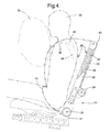
- the seat 10 comprises a lower frame 14, directly mounted to the vehicle body floor, and a seat back 16 that is pivoted relative to the lower frame 14 by a conventional recliner mechanism 18, rotating about a recliner pivot axis 20.
- a conventional reference frame shown in Figure 2 with the X axis running horizontally fore and aft, along the length of the vehicle body, the Y axis running horizontally side to side, and the Z axis running vertically, up and down.
- a length of the belt webbing constituting a lap belt 30 runs to a shackle 32 fixed to lower seat frame 14.
- both the shoulder belt 26 and lap belt 30 can be freely pulled out and adjusted by the occupant 22, but stays taught against the occupant 22.
- the retractor 24 locks up (allowing only a small payout of belt webbing) and all three belt webbing attachment points become effectively fixed.
- the occupant 22 moves relatively forwardly, but held down by the lap belt 30, and so tends to sit forward, bending from the waist. If the deployment threshold should be exceed, then a conventional air bag 34 inflates.
- the invention provides a mechanism that allows for controlled energy absorption in the shoulder belt 26, but with a conventional locking retractor mechanism 24.
- an elongated, flexible, resilient tower indicated generally at 36, extends along the outboard side of the seat back 16, generally vertically, or, at most with the same slight reclension from vertical that the seat back 16 has.
- the tower 36 makes a close fit within a sleeve 38 of seat back 16, and is constrained against bending at its lower end through a small portion of its lower length.
- Sleeve 38 is cut away on the front and inboard side so that the exposed upper length of tower 36, up to an uppermost, sliding belt guide 40, is unrestrained against bending forwardly and downwardly, in the X and Z direction.
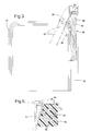
- Tower 36 is constructed with a central, flexible center reinforcement, which provides most of its resilience and strength.
- the center reinforcement is a steel coil spring 42, although it could be a leaf spring or the like, of any resilient and flexible material.
- the lower end of the coil spring 42 could be provided with a metal fastening member that would be bolted or otherwise securely fixed inside of seat back sleeve 38, while the belt guide 40 would be fixed to the upper end of spring 42.
- Spring 42 thereby provides a continuous mechanical connection from the lower end of tower 36 to the top.
- the strength of spring 42 would be set so as to allow the tower 38 to begin to bend forward if a force in the lower range of approximately 2 kN is applied to it at the upper end belt guide 40, and to reach the physical limit of its forward bending, set out in more detail below, at an upper range of approximately 4 kN.
- a surrounding damping layer 46 of polyurethane or other suitable polymeric material which provides the outer shape of tower 36 and protects the coil spring 42.
- the outer layer 46 can provide another useful feature.
- a structure such as a spring 42 alone will provide basically the same resistance if it is bent over slowly or rapidly.
- the resistance to bending, and consequent energy absorption can rise with the speed of bending imposed on the tower 36.
- the molded polyurethane layer 46 has many small closed cell air bubble inclusions 48, which resist rapid compression more forcefully than slow compression.
- Other polymeric materials inherently provide strain rate sensitivity, even without inclusions. This differential force response to the speed of deformation can provide an advantage described more fully below.
- the retractor 24 is fixed to the rear of seat back 16, substantially directly below the belt guide 40. It should be kept in mind that the retractor 24 is rigidly mounted to a part of seat back 16 that is not designed to bend or yield in any way with increased tension belt load, nor is any internal mechanism of retractor 24 intended to yield and absorb energy in response thereto. Retractor 24 simply locks fast onto the belt webbing in response to inertial loading, while allowing very little extra belt length to be paid out. The webbing runs from retractor 24, along the back of sleeve 38 and tower 36, and down over the tower belt guide 40 into the already defined shoulder belt 26.
- the length of webbing running between retractor 24 and the upper guide 40 which may conveniently be referred to as a reserve length 50, would, at first glance, appear to provide no obvious advantage, as compared to simply mounting the retractor 24 directly to the top of tower 36 in place of the belt guide 40.
- the advantage to mounting the retractor to the back of the seat frame was the ability to fix the retractor to a deformable beam in the seat frame.
- the upper point of attachment of the shoulder belt was secured to an inherently inflexible part of the seat frame or, in other designs, secured to a part of the seat frame that is itself deliberately constrained against flexure. But here, the upper shoulder belt attachment point provided by belt guide 40 is made flexible and movable, which provides several unique advantages detailed next.
- the increase in belt load is self limiting in that it quickly rises high enough, into the lower end of the force range noted above, to bend the tower 36 over.
- the tower 36 bends in three directions, forward along the X axis, downward along the Z axis, and inward along the Y axis.
- the limits of these three directions of bending are designed to be approximately 20 cm, 15 cm and 15 cm respectively, although the tower 36 will obviously bend less under less than maximum loading.
- the tension load in the shoulder belt 26 is rapidly reduced, since the belt reserve length 50, laying against the back of the bent over tower 36, moves from a vertical to a more horizontal orientation, allowing more of the belt webbing to slide relatively over the belt guide 40.
- the tower 36 does not just telescope downwardly along its length, however. Nor does it bend over loosely, of course, but absorbs and stores energy which would otherwise have to be absorbed by the very limited inherent stretch of the material of the belt webbing, or by an energy absorbing retractor.
- the forward and downward motion of the belt guide 40 provides other benefits in addition to reduced belt load. Since less force is applied to the seat back 16 at the belt guide 40, and since that point of application moves substantially closer to the recliner axis 20 as well, the resultant moment about axis 20 is reduced on both counts. Specifically, the moment can be reduced to 1400-1800 Nm, a very significant reduction in the 4250 Nm moment noted above. Deformation of the recliner mechanism 18, or of the brackets to which it is attached, is rendered less likely, and the seat back 16 is prevented from rotating forward out of it's original orientation.
- the occupant 22 is lain forwardly, downwardly, and slightly inboard by the motion of the tower 36 and shoulder belt 26, a favorable orientation for entry into the air bag 34.
- Overmolded layer 46 would dampen out the force and velocity of the rebound.
- the overmolded layer 46 can provide another advantage beyond rebound dampening.
- Frontal impact severity can vary, which increases both the rate of occupant deceleration relative to the tower 36 and the speed with which the tower 36 is deformed and bent over.
- a typical 35 mph frontal test crash into a fixed barrier such as that described above may impart a speed to the belt guide 40 of approximately Smm/millisecond.
- a more severe crash would impose a more rapid rate of deformation of tower 36, which would be more forcefully resisted by the tower 36, because of the strain rate sensitivity of the layer 46.
- An analogy would be the stiffer reaction of a vehicle shock absorber to wheel impact at higher speeds. This would translate to a higher tension load in the shoulder belt 26 than with lower speed frontal impacts, of course, but this is a desirable result, since a higher force applied through an equivalent displacement of tower 36 will also absorb more energy.
- the tower 36 of the invention is designed to yield substantially only to forces imposed by the deceleration associated with frontal impacts, and would not stretch along its length or bend easily in other directions than that shown.
- a tower like 36 could be applied to any seat, and on either or both sides thereof, though the outboard side is where the upper attachment point of a three point belt is typically found.
- a variety of composite structures could be used for the tower 36, in order to provide resilient flexibility combined with damping and/or strain rate sensitivity. Different cross sectional shapes could be used to cause the tower to favor bending to a selected side as it bent forwardly and down. Therefore, it will be understood that it is not intended to limit the invention to just the embodiment disclosed.
Landscapes
- Engineering & Computer Science (AREA)
- Mechanical Engineering (AREA)
- Aviation & Aerospace Engineering (AREA)
- Transportation (AREA)
- Automotive Seat Belt Assembly (AREA)
- Seats For Vehicles (AREA)
Applications Claiming Priority (2)
| Application Number | Priority Date | Filing Date | Title |
|---|---|---|---|
| US08/835,929 US5823627A (en) | 1997-04-11 | 1997-04-11 | Vehicle seat with integral, load limiting belt system |
| US835929 | 1997-04-11 |
Publications (2)
| Publication Number | Publication Date |
|---|---|
| EP0870652A2 true EP0870652A2 (fr) | 1998-10-14 |
| EP0870652A3 EP0870652A3 (fr) | 2001-01-24 |
Family
ID=25270820
Family Applications (1)
| Application Number | Title | Priority Date | Filing Date |
|---|---|---|---|
| EP98200783A Withdrawn EP0870652A3 (fr) | 1997-04-11 | 1998-03-12 | Siège pour véhicule avec système à ceinture intégré et limiteur de force |
Country Status (3)
| Country | Link |
|---|---|
| US (1) | US5823627A (fr) |
| EP (1) | EP0870652A3 (fr) |
| JP (1) | JP2944622B2 (fr) |
Cited By (4)
| Publication number | Priority date | Publication date | Assignee | Title |
|---|---|---|---|---|
| FR2856024A1 (fr) * | 2003-06-13 | 2004-12-17 | Hammerstein Gmbh C Rob | Unite de changement de direction de ceinture pour une ceinture de securite d'un vehicule automobile, en particulier d'une voiture decapotable ou d'un coupe |
| DE102005007428A1 (de) * | 2005-02-18 | 2006-08-31 | Volkswagen Ag | Fahrzeugsitz für ein Fahrzeug, insbesondere für ein Kraftfahrzeug |
| EP2492140A3 (fr) * | 2011-02-25 | 2013-05-08 | Grammer Ag | Siège de véhicule, procédé de réduction d'une introduction de forces et/ou de moment et utilisation d'une fixation de suspension de ceinture |
| CN108407751A (zh) * | 2018-02-02 | 2018-08-17 | 吉利汽车研究院(宁波)有限公司 | 一种汽车座椅安全带的布置结构 |
Families Citing this family (48)
| Publication number | Priority date | Publication date | Assignee | Title |
|---|---|---|---|---|
| GB2309889B (en) * | 1996-02-06 | 1999-05-26 | Autoliv Dev | Improvements in or relating to a vehicle seat |
| US6276721B1 (en) * | 2000-03-14 | 2001-08-21 | Simula, Inc. | Pivoting seat belt upper anchor point attachment |
| DE19800071A1 (de) * | 1998-01-02 | 1999-07-08 | Volkswagen Ag | Rückhalteeinrichtung mit einem Sicherheitsgurt |
| FR2777518B1 (fr) * | 1998-04-17 | 2000-06-16 | Faure Bertrand Equipements Sa | Armature de dossier de siege de vehicule automobile |
| US6886889B2 (en) | 1998-10-30 | 2005-05-03 | Indiana Mills & Manufacturing, Inc. | Restraint system for a vehicle |
| US6123388A (en) * | 1998-10-30 | 2000-09-26 | Indiana Mills & Manufacturing, Inc. | Restraint system for a school bus seat |
| US7040696B2 (en) | 1998-10-30 | 2006-05-09 | Indiana Mills & Manufacturing, Inc. | System of seats for a vehicle |
| US6485098B1 (en) | 1998-10-30 | 2002-11-26 | Indiana Mills & Manufacturing, Inc. | Restraint system for a school bus seat |
| US6045186A (en) * | 1998-12-04 | 2000-04-04 | Johnson Controls Technology Company | High tension back frame for vehicle seat assembly |
| US6145881A (en) * | 1999-01-15 | 2000-11-14 | Breed Automotive Technology Inc. | Seatback mounted seat belt tensioner |
| US6056366A (en) * | 1999-02-26 | 2000-05-02 | Lear Corporation | Composite back frame for a vehicle seat and method for distributing seat belt loads |
| JP3714039B2 (ja) * | 1999-06-18 | 2005-11-09 | 日産自動車株式会社 | シートベルト一体シート |
| SE9903319L (sv) * | 1999-09-16 | 2001-03-17 | Saab Automobile | Anordning vid ett säkerhetsbälte i ett motorfordon |
| US6260926B1 (en) | 2000-02-28 | 2001-07-17 | Leonard James Meraw | Energy absorbing webbing for seat belt systems |
| DE10035148B4 (de) * | 2000-07-19 | 2012-12-06 | Volkswagen Ag | Rückhaltevorrichtung |
| JP2002283891A (ja) * | 2001-03-23 | 2002-10-03 | Johnson Controls Automotive Systems Corp | 車両用シートにおけるシートバックフレーム |
| US6601923B2 (en) * | 2001-08-23 | 2003-08-05 | Seats Incorporated | Emergency vehicle seat with integrated seat belt |
| DE10156599C1 (de) * | 2001-11-17 | 2003-05-15 | Norbert Janz | Gurtumlenker an einem Fahrzeugsitz |
| US6796192B2 (en) * | 2001-12-19 | 2004-09-28 | Delphi Technologies, Inc. | Pass through seat restraint tension sensing assembly |
| US6896324B1 (en) * | 2002-04-19 | 2005-05-24 | Adam Aircraft Industries | Hybrid composite-metal energy absorbing seat |
| US6851503B2 (en) * | 2002-10-01 | 2005-02-08 | Delphi Technologies, Inc. | Seat belt tension sensor assembly |
| US6931940B2 (en) | 2002-10-02 | 2005-08-23 | Delphi Technologies, Inc. | Magnetostrictive strain sensor with hall effect |
| DE10251081B4 (de) * | 2002-11-02 | 2005-06-16 | Janz, Norbert, Dipl.-Ing. | Gurtumlenker an einem Sitz, insbesondere einem Fahrzeugsitz |
| JP4337380B2 (ja) * | 2003-03-25 | 2009-09-30 | アイシン精機株式会社 | シートリクライニング装置 |
| US6952974B2 (en) * | 2003-06-12 | 2005-10-11 | Delphi Technologies, Inc. | Seat belt tension sensor |
| US7866696B2 (en) * | 2004-12-10 | 2011-01-11 | GM Global Technology Operations LLC | Vehicle seat assembly |
| JP4612519B2 (ja) * | 2005-10-11 | 2011-01-12 | 三菱自動車工業株式会社 | リクライニングシートの構造 |
| FR2896460B1 (fr) * | 2006-01-26 | 2016-03-04 | Hammerstein Gmbh C Rob | Siege a ceinture integree avec dispositif de reglage longitudinal. |
| JP5187119B2 (ja) * | 2008-10-10 | 2013-04-24 | トヨタ紡織株式会社 | 車両用シートの操作レバー構造体 |
| US8419127B1 (en) * | 2009-12-11 | 2013-04-16 | Armorworks Enterprises LLC. | Moveable seatbelt support |
| JP5473660B2 (ja) * | 2010-02-15 | 2014-04-16 | 三菱自動車工業株式会社 | シートベルトガイド構造 |
| JP5599625B2 (ja) * | 2010-02-26 | 2014-10-01 | テイ・エス テック株式会社 | 車両用シート |
| EP2616272B1 (fr) * | 2010-09-14 | 2017-06-21 | Basf Se | Support à absorption d'énergie destiné au siège d'un véhicule |
| US9469272B2 (en) | 2013-03-15 | 2016-10-18 | Autoliv Asp, Inc. | Load limiting seat belt retractor with spiral turn limiter |
| US10196033B2 (en) * | 2016-07-18 | 2019-02-05 | Ford Global Technologies, Llc | Seat mounted adjustable seat belt webbing guide |
| US10899311B2 (en) * | 2017-12-27 | 2021-01-26 | Toyota Jidosha Kabushiki Kaisha | Passenger restraining device for vehicle |
| DE202017107933U1 (de) * | 2017-12-28 | 2018-04-06 | Lear Corporation | Austrittsverkleidungsanordnung für einen Schultergurt in einem Fahrzeug |
| US11458867B2 (en) * | 2019-01-07 | 2022-10-04 | Adient Us Llc | Occupant support component for a seat of a vehicle and vehicle seat |
| US11628749B2 (en) | 2020-02-26 | 2023-04-18 | GM Global Technology Operations LLC | Vehicle seat for a motor vehicle and method of positioning the same |
| US11623607B1 (en) * | 2022-02-28 | 2023-04-11 | Nissan North America, Inc. | Vehicle seat assembly |
| US12037120B2 (en) * | 2022-03-29 | 2024-07-16 | B/E Aerospace, Inc. | Passenger restraints for reducing spinal tension |
| US12060034B1 (en) * | 2023-02-03 | 2024-08-13 | B/E Aerospace, Inc. | Seat belt assemblies for mitigating spinal tension during free-flail |
| DE102023114893B4 (de) * | 2023-06-06 | 2025-01-09 | Grammer Aktiengesellschaft | Fahrzeugsitz mit Gurtsystem |
| US12454242B2 (en) * | 2023-07-21 | 2025-10-28 | Ford Global Technologies, Llc | Vehicle seat and seatbelt assembly |
| KR20250022436A (ko) * | 2023-08-08 | 2025-02-17 | 현대자동차주식회사 | 시트벨트 장치 및 그 장착방법 |
| US12370975B2 (en) * | 2023-09-15 | 2025-07-29 | Ford Global Technologies, Llc | Seatbelt guide mechanism |
| FR3154959B1 (fr) * | 2023-11-07 | 2025-10-24 | Renault Sas | Siège pour véhicule automobile à ceinture de sécurité intégrée |
| DE102024104760B3 (de) | 2024-02-21 | 2025-02-20 | Bayerische Motoren Werke Aktiengesellschaft | Fahrzeugsitzanordnung mit einem Insassenrückhaltesystem und Fahrzeug |
Citations (2)
| Publication number | Priority date | Publication date | Assignee | Title |
|---|---|---|---|---|
| US5318341A (en) | 1992-01-28 | 1994-06-07 | Hoover Universal, Inc. | Vehicle seat assembly with structural seat back to accommodate seat belt loads applied to seat back |
| US5468053A (en) | 1994-05-04 | 1995-11-21 | Reynolds Metals Company | Energy absorbing beam construction for use with vehicle seat belt restraining systems |
Family Cites Families (9)
| Publication number | Priority date | Publication date | Assignee | Title |
|---|---|---|---|---|
| FR2162940A5 (fr) * | 1971-11-23 | 1973-07-20 | Gen Motors Corp | |
| DE2546157C3 (de) * | 1975-10-15 | 1979-11-22 | Roland 8731 Euerdorf Satzinger | Sicherheitssitz für Kraftfahrzeuge |
| US5020856A (en) * | 1986-11-18 | 1991-06-04 | Volvo Gm Heavy Truck Corporation | Three-point seat belt |
| US4889389A (en) * | 1987-10-13 | 1989-12-26 | Grumman Allied Industries, Inc. | Seat with three point user restraint |
| JP3079603B2 (ja) * | 1991-03-15 | 2000-08-21 | アイシン精機株式会社 | シートバツクフレーム |
| US5253924A (en) * | 1991-06-11 | 1993-10-19 | Concept Analysis Corporation | Blow molded seat back with integral reinforcing member |
| DE4218792A1 (de) * | 1992-06-06 | 1993-12-09 | Bayerische Motoren Werke Ag | Dreipunktsicherheitsgurtsystem für Kraftfahrzeuge |
| US5447360A (en) * | 1993-09-30 | 1995-09-05 | Hoover Universal, Inc. | Side impact seat back structure |
| US5547259A (en) * | 1994-05-09 | 1996-08-20 | Mitchell Corporation Of Owosso, Inc. | Modular automotive seat frame |
-
1997
- 1997-04-11 US US08/835,929 patent/US5823627A/en not_active Expired - Fee Related
-
1998
- 1998-03-12 EP EP98200783A patent/EP0870652A3/fr not_active Withdrawn
- 1998-04-13 JP JP10100863A patent/JP2944622B2/ja not_active Expired - Fee Related
Patent Citations (2)
| Publication number | Priority date | Publication date | Assignee | Title |
|---|---|---|---|---|
| US5318341A (en) | 1992-01-28 | 1994-06-07 | Hoover Universal, Inc. | Vehicle seat assembly with structural seat back to accommodate seat belt loads applied to seat back |
| US5468053A (en) | 1994-05-04 | 1995-11-21 | Reynolds Metals Company | Energy absorbing beam construction for use with vehicle seat belt restraining systems |
Cited By (6)
| Publication number | Priority date | Publication date | Assignee | Title |
|---|---|---|---|---|
| FR2856024A1 (fr) * | 2003-06-13 | 2004-12-17 | Hammerstein Gmbh C Rob | Unite de changement de direction de ceinture pour une ceinture de securite d'un vehicule automobile, en particulier d'une voiture decapotable ou d'un coupe |
| DE102005007428A1 (de) * | 2005-02-18 | 2006-08-31 | Volkswagen Ag | Fahrzeugsitz für ein Fahrzeug, insbesondere für ein Kraftfahrzeug |
| EP2492140A3 (fr) * | 2011-02-25 | 2013-05-08 | Grammer Ag | Siège de véhicule, procédé de réduction d'une introduction de forces et/ou de moment et utilisation d'une fixation de suspension de ceinture |
| CN103144560A (zh) * | 2011-02-25 | 2013-06-12 | 格拉默股份公司 | 车辆座椅与减少力和/或力矩引入的方法及带悬挂紧固装置的应用 |
| CN103144560B (zh) * | 2011-02-25 | 2016-10-12 | 格拉默股份公司 | 车辆座椅与减少力和/或力矩引入的方法及带悬挂紧固装置的应用 |
| CN108407751A (zh) * | 2018-02-02 | 2018-08-17 | 吉利汽车研究院(宁波)有限公司 | 一种汽车座椅安全带的布置结构 |
Also Published As
| Publication number | Publication date |
|---|---|
| JPH10278736A (ja) | 1998-10-20 |
| US5823627A (en) | 1998-10-20 |
| EP0870652A3 (fr) | 2001-01-24 |
| JP2944622B2 (ja) | 1999-09-06 |
Similar Documents
| Publication | Publication Date | Title |
|---|---|---|
| US5823627A (en) | Vehicle seat with integral, load limiting belt system | |
| US8240736B2 (en) | Deceleration responsive vehicle seat | |
| EP0447364B1 (fr) | Ceinture de sécurité intégrée à un siège | |
| JPS5930772Y2 (ja) | 乗物座席安全装置 | |
| US5295729A (en) | High retention seat back | |
| US6139111A (en) | Four point seat-mounted restraint apparatus | |
| US6481777B2 (en) | Tethering apparatus for a pedestal mounted vehicle seat | |
| US4993778A (en) | Reinforced framework for a vehicle seat | |
| JP5477537B2 (ja) | 車両のシートベルト装置 | |
| US20010038233A1 (en) | Chair structure | |
| KR20110104919A (ko) | 구조적 지지를 갖는 아동 안전 좌석 | |
| CA2592795A1 (fr) | Ensemble de siege a contention du passager avec dispositif d'absorption d'energie par detection de charge | |
| CN111183058A (zh) | 带有乘客保护系统的具有车辆内舱中可供使用的增大的自由空间的车辆 | |
| CN112172629A (zh) | 冲击吸收装置以及交通工具用座椅 | |
| US5590907A (en) | Seat belt positioning device and system | |
| JPH11321559A (ja) | シートベルト用バックル装置 | |
| US5749601A (en) | Belt force limiter for a vehicle seat belt | |
| US6402218B1 (en) | Seat belt pretensioner device powered by vehicle body deformation | |
| US11623607B1 (en) | Vehicle seat assembly | |
| CN110843722A (zh) | 车辆座椅安全带系统 | |
| US4213651A (en) | Seatbelt system | |
| GB2183988A (en) | Device for attaching a safety belt to a vehicle seat | |
| US4264091A (en) | Anchorage system for restraint belt | |
| EP1070640B1 (fr) | Prétensionneur de ceinture de sécurité utilisant la déformation du chassis d'un véhicule | |
| WO1991012979A1 (fr) | Agencement de ceinture de securite |
Legal Events
| Date | Code | Title | Description |
|---|---|---|---|
| PUAI | Public reference made under article 153(3) epc to a published international application that has entered the european phase |
Free format text: ORIGINAL CODE: 0009012 |
|
| AK | Designated contracting states |
Kind code of ref document: A2 Designated state(s): AT BE CH DE DK ES FI FR GB GR IE IT LI LU MC NL PT SE |
|
| AX | Request for extension of the european patent |
Free format text: AL;LT;LV;MK;RO;SI |
|
| RAP1 | Party data changed (applicant data changed or rights of an application transferred) |
Owner name: LEAR CORPORATION Owner name: GENERAL MOTORS CORPORATION |
|
| PUAL | Search report despatched |
Free format text: ORIGINAL CODE: 0009013 |
|
| AK | Designated contracting states |
Kind code of ref document: A3 Designated state(s): AT BE CH DE DK ES FI FR GB GR IE IT LI LU MC NL PT SE |
|
| AX | Request for extension of the european patent |
Free format text: AL;LT;LV;MK;RO;SI |
|
| RIC1 | Information provided on ipc code assigned before grant |
Free format text: 7B 60R 22/26 A, 7B 60N 2/44 B |
|
| STAA | Information on the status of an ep patent application or granted ep patent |
Free format text: STATUS: THE APPLICATION IS DEEMED TO BE WITHDRAWN |
|
| 18D | Application deemed to be withdrawn |
Effective date: 20001003 |