EP0870660A2 - Einstellvorrichtung mit selbsttätigem Längenausgleich für einen Betätigungszug, insbesondere für Kraftfahrzeuge - Google Patents
Einstellvorrichtung mit selbsttätigem Längenausgleich für einen Betätigungszug, insbesondere für Kraftfahrzeuge Download PDFInfo
- Publication number
- EP0870660A2 EP0870660A2 EP98106248A EP98106248A EP0870660A2 EP 0870660 A2 EP0870660 A2 EP 0870660A2 EP 98106248 A EP98106248 A EP 98106248A EP 98106248 A EP98106248 A EP 98106248A EP 0870660 A2 EP0870660 A2 EP 0870660A2
- Authority
- EP
- European Patent Office
- Prior art keywords
- lever
- lever arm
- arm
- cable
- adjusting device
- Prior art date
- Legal status (The legal status is an assumption and is not a legal conclusion. Google has not performed a legal analysis and makes no representation as to the accuracy of the status listed.)
- Withdrawn
Links
Images

Classifications
-
- F—MECHANICAL ENGINEERING; LIGHTING; HEATING; WEAPONS; BLASTING
- F16—ENGINEERING ELEMENTS AND UNITS; GENERAL MEASURES FOR PRODUCING AND MAINTAINING EFFECTIVE FUNCTIONING OF MACHINES OR INSTALLATIONS; THERMAL INSULATION IN GENERAL
- F16C—SHAFTS; FLEXIBLE SHAFTS; ELEMENTS OR CRANKSHAFT MECHANISMS; ROTARY BODIES OTHER THAN GEARING ELEMENTS; BEARINGS
- F16C1/00—Flexible shafts; Mechanical means for transmitting movement in a flexible sheathing
- F16C1/10—Means for transmitting linear movement in a flexible sheathing, e.g. "Bowden-mechanisms"
- F16C1/22—Adjusting; Compensating length
-
- B—PERFORMING OPERATIONS; TRANSPORTING
- B60—VEHICLES IN GENERAL
- B60T—VEHICLE BRAKE CONTROL SYSTEMS OR PARTS THEREOF; BRAKE CONTROL SYSTEMS OR PARTS THEREOF, IN GENERAL; ARRANGEMENT OF BRAKING ELEMENTS ON VEHICLES IN GENERAL; PORTABLE DEVICES FOR PREVENTING UNWANTED MOVEMENT OF VEHICLES; VEHICLE MODIFICATIONS TO FACILITATE COOLING OF BRAKES
- B60T11/00—Transmitting braking action from initiating means to ultimate brake actuator without power assistance or drive or where such assistance or drive is irrelevant
- B60T11/04—Transmitting braking action from initiating means to ultimate brake actuator without power assistance or drive or where such assistance or drive is irrelevant transmitting mechanically
- B60T11/06—Equalising arrangements
-
- B—PERFORMING OPERATIONS; TRANSPORTING
- B60—VEHICLES IN GENERAL
- B60T—VEHICLE BRAKE CONTROL SYSTEMS OR PARTS THEREOF; BRAKE CONTROL SYSTEMS OR PARTS THEREOF, IN GENERAL; ARRANGEMENT OF BRAKING ELEMENTS ON VEHICLES IN GENERAL; PORTABLE DEVICES FOR PREVENTING UNWANTED MOVEMENT OF VEHICLES; VEHICLE MODIFICATIONS TO FACILITATE COOLING OF BRAKES
- B60T7/00—Brake-action initiating means
- B60T7/02—Brake-action initiating means for personal initiation
- B60T7/08—Brake-action initiating means for personal initiation hand actuated
- B60T7/10—Disposition of hand control
- B60T7/108—Disposition of hand control with mechanisms to take up slack in the linkage to the brakes
Definitions
- the invention relates to an adjusting device automatic length compensation for control cables such as cable pulls or the like, in particular for actuating vehicle brakes by means of an actuating element with a lever device, which is articulated at one point to a vehicle-fixed point is and at the other end a recording for the Has actuating element leading cable and with one Bracket with holder for those leading to the brakes Cable is connected.
- DE 3741350 A1 already includes an adjusting device the features mentioned above, which are known for the parking brake of a motor vehicle is determined.
- the device has a Adjustable elongated transmission link on, on which is arranged a double-arm compensation yoke, the in turn rope strands leading to a wheel brake holds.
- the lever arms of the compensation yoke are relative to one another pivoted and for the transmission of braking forces in the one pivoting direction by means of a locking device prevented from pivoting. A jig tried while doing so, the lever arms of the compensating yoke into the other Direction. Because the compensation or Adjustment movement by two on the bracket for the to Brake leading cables is provided is the well-known Device constructed quite complicated.
- DE 19546931 A1 already has one Known adjustment device that i.w. case-like Support with two swivel-mounted, by spring elements has prestressed locking segments. The rest segments are each connectable with a cable. Furthermore, an in a receptacle slidably provided, which when the cable is actuated by one Locking segments unlock the position in one of the locking segments blocking position is transferable.
- this known setting device has proven itself in practice, there is a need for a new adjustment device more compact design. It should also be borne in mind that the installation space available for the adjusting device, for example in the area of the operating lever itself or in Area of the vehicle in which a branching of the Actuating cables to the two rear wheel brakes is provided, may be very small.
- the invention is based on the object, a Adjustment device with a compact design and construction easy to create.
- the lever device has two lever arms connected by means of a pivot bearing, swivel joint or the like, which can be determined by means of a locking mechanism in a relative angular position, the angular position depending on the respective length compensation is adjustable.
- the means for automatic length compensation are not arranged in the area of the bracket, but in the area of the lever device, a structurally simple or inexpensive device is created which can also be used in a space-restricted installation space in the respective motor vehicle.
- a first advantageous embodiment is characterized by this from that the two lever arms at one end of the point fixed to the vehicle by means of the pivot bearing or the like are.
- the first Lever arm has a slot-like opening, through which is a fastener of the bracket on the second Lever arm is inserted. This is a free one Swiveling or changing the relative angular position of the two lever arms in the case of the extension of a cable without further possible.
- the second lever arm at one end on the vehicle Point articulated and at the other end using the pivot bearing or Like. Is connected to the first lever arm. In this case it is possible to fix the bracket to the pivot bearing to connect the two lever arms.
- the locking mechanism is in accordance with one embodiment of the invention a pawl and a correspondingly adapted toothing formed, the teeth arranged on the one lever arm and locking on the other lever arm, for example by means of a Bolzens or the like. Are pivotally attached.
- the teeth or the pawl advantageously have one asymmetrical shape, such as sawtooth or the like.
- actuation of the actuating element accompanying pivoting of the lever device for a safe Determination of the relative angular position of the two lever arms concerned while in the event of non-actuation of the lever element and one that may become necessary
- Length compensation is the relative angular position of the two lever arms can easily be changed by the pawl so to speak ratchets over the teeth of one lever arm until the two lever arms a new, relative angular position to Have accepted length compensation.
- lever arms by means of a spring element, in particular the tension spring, with a bias are.
- the preload works in the sense of an effective one Shortening the length of the cables, so that in particular any Loose in the adjustment system can be compensated.
- the bracket is advantageous by a balance arm and a Compensation element formed, the compensation element approximately is articulated in the middle of the compensating arm and on the both ends of the receptacle for the brakes leading cables.
- the compensating element with the other end of the balance arm is pivotally connected, so that different elongations in the leading to the brakes Cable pulls by swiveling the Compensating elements are compensated for on the compensating arm can.
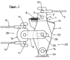
- the setting device 20 shown in the figures is used for automatic length compensation for cables 3, 12, 13 with which for example the vehicle brakes by means of an actuating element, like hand brake lever, can be operated.
- the Adjustment device 20 has a lever device 22 which articulated at one end at a point 24 fixed to the vehicle is. At the other end, the lever device 22 has a receptacle 26 for the cable 3 leading to the actuating element.
- the lever device 22 is provided with a holder 28 connected, the recordings 11 for the leading to the brakes Has cables 12, 13.
- the lever device has two by means of a pivot bearing 14, Swivel joint or the like connected lever arms 2, 7.
- the lever arms 2, 7 are relative by means of a locking mechanism 1 Angular position to each other can be determined.
- the angular position is in Depending on the length compensation.
- the locking mechanism 1 is by a pawl 4 and a set of teeth 6 formed, the toothing 6 on one lever arm 2, 7 arranged and the pawl 4 on the other lever arm 7, 2,
- a bolt 5 or the like pivotally attached are.
- the pawl 4 by means of a Spring element, in particular a tension spring 8, in the locked position biased.
- the teeth 6 and the pawl 4 have one asymmetrical shape, such as sawtooth or the like
- lever arms 2, 7 are by means of a Spring element, in particular tension spring 8, with a bias acted upon.
- the bracket 28 is a balance arm 9 and a Compensation element 10 formed.
- the balance arm 9 is one end pivotally connected to at least one of the lever arms 2, 7.
- the compensating element 10 is at the other end of the Compensating arm 9 is also pivotally articulated.
- the two lever arms 2, 7 at one end at the vehicle-fixed point 24 by means of the pivot bearing 14 or the like.
- the receptacle 26 for the cable 3 is arranged on the first lever arm 2, the bracket 28 with the second lever arm 7 is connected.
- the first lever arm 2 has a slot-like opening 30 through which a Fastening element 32 of the holder 28 on the second lever arm 7 is stuck.
- Figure 2 shows the second lever arm 7 at one end of the vehicle Point 24 articulated and at the other end by means of the pivot bearing 14 or the like. Connected to the first lever arm 2.
- the recording 26 for the cable 3 is also on the first lever arm 2 arranged, the bracket 28 with the pivot bearing 14 of the Lever arms 2, 7 is connected.
- the embodiment of Figure 2 has compared to that of Figure 1 so far a different construction on, than the pivot bearing 14 for the two lever arms 2, 7 not at the vehicle-fixed point 24, but at the free end of the Lever arm 7 is arranged.
- the toothing 6 also acts of the lever arm 2 with that at the point 24 fixed to the vehicle stored pawl 4 together. Also in that The exemplary embodiment in FIG. 2 is between the lever arm 2 or a nose-shaped approach of the lever arm 2 and the Pawl 4 or the articulated on the point 24 fixed to the vehicle Lever arm 7 a tension spring 8 tensioned.
- Adjustment device 20 has in common that due to the Use of a lever device 22 consisting of two Lever arms 2, 7, if a rope loose occurs in the System the relative angular position of the lever arms 2, 7 such is changed that the distance between the recordings 11 and 26th ultimately shortened and thus the rope loose from the system is taken.
- the lever arms 2, 7 are by means of the tension spring 8 towards shortening the distance between the Images 11 and 26 preloaded, the locking mechanism 1 for this ensures that, on the one hand, the ropes are automatically removed from the system removed and on the other hand for a secure fixation of the the respective angular position of the two lever arms 2, 7 is taken care of, as soon as by actuating the actuating element by means of the Cable 3 exerted a tensile force on the lever device 22 becomes.
Landscapes
- Engineering & Computer Science (AREA)
- Mechanical Engineering (AREA)
- General Engineering & Computer Science (AREA)
- Transportation (AREA)
- Health & Medical Sciences (AREA)
- Oral & Maxillofacial Surgery (AREA)
- Flexible Shafts (AREA)
- Mechanical Control Devices (AREA)
- Braking Elements And Transmission Devices (AREA)
Abstract
Description
- Figur 1
- ein erstes Ausführungsbeispiel der Erfindung in Seitenansicht und schematischer Darstellung und
- Figur 2
- ein zweites Ausführungsbeispiel der Erfindung in Seitenansicht und schematischer Darstellung.
- 1
- Gesperre
- 2
- Hebelarm
- 3
- Seilzug
- 4
- Sperrklinke
- 5
- Bolzen
- 6
- Zahnung
- 7
- Hebelarm
- 8
- Zugfeder
- 9
- Ausgleichsarm
- 10
- Ausgleichselement
- 11
- Aufnahmen
- 12
- Seilzug
- 13
- Seilzug
- 14
- Drehlager
- 20
- Einstellvorrichtung
- 22
- Hebelvorrichtung
- 24
- fahrzeugfester Punkt
- 26
- Aufnahme
- 28
- Halterung
- 30
- Durchbrechung
- 32
- Befestigungselement
Claims (13)
- Einstellvorrichtung (20) mit selbsttätigem Längenausgleich für Betätigungszüge, wie Seilzüge (3, 12, 13), zur Betätigung von Fahrzeugbremsen oder dgl. mittels eines Betätigungselements mit einer Hebelvorrichtung (22), die einends schwenkbar an einem fahrzeugfesten Punkt (24) angelenkt ist und anderenends eine Aufnahme (26) für den zum Betätigungselement führenden Seilzug (3) aufweist, wobei mit der Hebelvorrichtung (22) eine Halterung (28) mit Aufnahmen (11) für die zu den Bremsen oder dgl. führenden Seilzüge (12, 13) verbunden ist, dadurch gekennzeichnet, daß die Hebelvorrichtung (22) zwei mittels eines Drehlagers (14), Drehgelenks oder dgl. verbundene Hebelarme (2, 7) aufweist, welche mittels eines Gesperres (1) in einer relativen Winkellage feststellbar sind, wobei die Winkellage in Abhängigkeit von dem jeweiligen Längenausgleich einstellbar ist.
- Einstellvorrichtung nach Anspruch 1, dadurch gekennzeichnet, daß die zwei Hebelarme (2, 7) jeweils einends an dem fahrzeugfesten Punkt (24) mittels des Drehlagers (14) oder dgl. angelenkt sind.
- Einstellvorrichtung nach einem der Ansprüche 1, Zusatz 2, dadurch gekennzeichnet, daß die Aufnahme (26) für den Seilzug (3) zum Bremsgeber am ersten Hebelarm (2) angeordnet und die Halterung (28) für die Seilzüge (12, 13) zu den Radbremsen mit dem zweiten Hebelarm (7) verbunden ist.
- Einstellvorrichtung nach Anspruch 3, dadurch gekennzeichnet, daß der erste Hebelarm (2) eine langlochartige Durchbrechung (30) aufweist, durch welche ein Befestigungselement (32) der Halterung (28) am zweiten Hebelarm (7) gesteckt ist.
- Einstellvorrichtung nach Anspruch 1, dadurch gekennzeichnet, daß der zweite Hebelarm (7) einends an dem fahrzeugfesten Punkt (24) angelenkt und anderenends mittels des Drehlagers (14) oder dgl. mit dem ersten Hebelarm (2) verbunden ist.
- Einstellvorrichtung nach Anspruch 5, dadurch gekennzeichnet, daß die Aufnahme (26) für den Seilzug (3) am ersten Hebelarm (2) angeordnet und die Halterung (28) mit dem Drehlager (14) der Hebelarme (2, 7) verbunden sind.
- Einstellvorrichtung nach einem der vorhergehenden Ansprüche, dadurch gekennzeichnet, daß das Gesperre (1) durch eine Sperrklinke (4) sowie eine Zahnung (6) gebildet ist, wobei die Zahnung (6) an dem einen Hebelarm (2, 7) angeordnet und die Sperrklinke (4) an dem anderen Hebelarm (7, 2), bspw. mittels eines Bolzens oder dgl. schwenkbar befestigt sind.
- Einstellvorrichtung nach Anspruch 5, dadurch gekennzeichnet, daß die Sperrklinke (4) mittels eines Federelements, insbesondere einer Zugfeder (8) in Sperrstellung vorgespannt ist.
- Einstellvorrichtung nach einem der Ansprüche 7 oder 8, dadurch gekennzeichnet, daß die Zahnung (6) bzw. die Sperrklinke (4) eine asymmetrische Formgebung, wie Sägezahn oder dgl. aufweist.
- Einstellvorrichtung nach einem der vorhergehenden Ansprüche, dadurch gekennzeichnet, daß die Hebelarme (2, 7) mittels eines Federelements, insbesondere einer Zugfeder (8), mit einer Vorspannung beaufschlagt sind.
- Einstellvorrichtung nach einem der vorgehenden Ansprüche, dadurch gekennzeichnet, daß die Halterung (28) durch einen Ausgleichsarm (9) und ein Ausgleichselement (10) gebildet ist.
- Einstellvorrichtung nach Anspruch 11, dadurch gekennzeichnet, daß der Ausgleichsarm (9) einends mit wenigstens einem Hebelarm (2, 7) schwenkbar verbunden ist.
- Einstellvorrichtung nach Anspruch 12, dadurch gekennzeichnet, daß das Ausgleichselement (10) mit den anderen Ende des Ausgleichsarms (9) schwenkbar verbunden ist.
Applications Claiming Priority (4)
| Application Number | Priority Date | Filing Date | Title |
|---|---|---|---|
| DE19715307 | 1997-04-11 | ||
| DE19715307 | 1997-04-11 | ||
| DE19734573A DE19734573C2 (de) | 1997-04-11 | 1997-08-09 | Einstellvorrichtung mit selbsttätigem Längenausgleich für Seilzüge, insbesondere für Fahrzeugbremsen |
| DE19734573 | 1997-08-09 |
Publications (2)
| Publication Number | Publication Date |
|---|---|
| EP0870660A2 true EP0870660A2 (de) | 1998-10-14 |
| EP0870660A3 EP0870660A3 (de) | 1999-05-06 |
Family
ID=26035725
Family Applications (1)
| Application Number | Title | Priority Date | Filing Date |
|---|---|---|---|
| EP98106248A Withdrawn EP0870660A3 (de) | 1997-04-11 | 1998-04-06 | Einstellvorrichtung mit selbsttätigem Längenausgleich für einen Betätigungszug, insbesondere für Kraftfahrzeuge |
Country Status (1)
| Country | Link |
|---|---|
| EP (1) | EP0870660A3 (de) |
Cited By (1)
| Publication number | Priority date | Publication date | Assignee | Title |
|---|---|---|---|---|
| CN118327394A (zh) * | 2024-04-18 | 2024-07-12 | 重庆长安汽车股份有限公司 | 一种前罩锁的调节结构及前罩锁、车辆 |
Families Citing this family (1)
| Publication number | Priority date | Publication date | Assignee | Title |
|---|---|---|---|---|
| DE102005000804B4 (de) * | 2005-01-05 | 2011-06-16 | FICO CABLES S.A. Technological Centre Pujol & Tarragó | Handbremshebelsystem |
Family Cites Families (3)
| Publication number | Priority date | Publication date | Assignee | Title |
|---|---|---|---|---|
| US2907228A (en) * | 1955-03-07 | 1959-10-06 | American Forging & Socket Co | Hand brake system |
| DE3741530A1 (de) * | 1987-12-08 | 1989-06-29 | Daimler Benz Ag | Nachstellvorrichtung fuer eine feststellbremse eines kraftfahrzeuges |
| DE19718320C2 (de) * | 1996-05-07 | 1999-07-01 | Kuester & Co Gmbh | Einstellvorrichtung mit selbsttätigem Längenausgleich für ein Seilzugsystem o. dgl. |
-
1998
- 1998-04-06 EP EP98106248A patent/EP0870660A3/de not_active Withdrawn
Cited By (1)
| Publication number | Priority date | Publication date | Assignee | Title |
|---|---|---|---|---|
| CN118327394A (zh) * | 2024-04-18 | 2024-07-12 | 重庆长安汽车股份有限公司 | 一种前罩锁的调节结构及前罩锁、车辆 |
Also Published As
| Publication number | Publication date |
|---|---|
| EP0870660A3 (de) | 1999-05-06 |
Similar Documents
| Publication | Publication Date | Title |
|---|---|---|
| DE68916526T4 (de) | Fahrzeug-Türschlosssystem. | |
| DE10154659C5 (de) | Zusammenschiebbare Lenksäulenanordnung für ein Fahrzeug | |
| DE2160278C2 (de) | Selbstnachstellende Betätigungsvorrichtung für eine Kraftfahrzeugkupplung | |
| DE102007059744A1 (de) | Getriebebaueinheit einer Verstelleinrichtung eines Kraftfahrzeugs | |
| DE4211566A1 (de) | Mit einer selbsttätigen Nachstelleinrichtung versehene Handbremse | |
| EP0754135B1 (de) | Feststellbremse für kraftfahrzeuge, fahrzeuganhänger oder dergleichen | |
| DE29600996U1 (de) | Feststellbremse für Kraftfahrzeuge, Fahrzeuganhänger o.dgl. | |
| EP3915829A1 (de) | Fahrzeugsitzbeschlag und fahrzeugsitz | |
| DE19936733C2 (de) | Betätigungseinrichtung für eine Feststellbremse | |
| EP0300470A1 (de) | Vorrichtung zum Ankoppeln des mit dem Gurtschloss eines Sicherheitsgurtes versehenen Tragstücks an ein fahrzeugfestes Halteteil | |
| EP0904990A1 (de) | Betätigungseinheit | |
| EP0904223B1 (de) | Einstellvorrichtung mit selbsttätigem längenausgleich für einen betätigungszug | |
| DE19734573C2 (de) | Einstellvorrichtung mit selbsttätigem Längenausgleich für Seilzüge, insbesondere für Fahrzeugbremsen | |
| WO2001096161A2 (de) | Feststellbremse | |
| EP1851085B1 (de) | Vorrichtung zur Verriegelung und Entriegelung und Kraftfahrzeugsitz mit einer solchen Vorrichtung | |
| EP0950589A2 (de) | Blockiereinrichtung für ein Fahrzeug | |
| DE10230855B4 (de) | Pedalanordnung und Montageverfahren hierfür | |
| EP0870660A2 (de) | Einstellvorrichtung mit selbsttätigem Längenausgleich für einen Betätigungszug, insbesondere für Kraftfahrzeuge | |
| DE102004040881B4 (de) | Fahrzeugsitz | |
| DE19600582B4 (de) | Feststellbremse für ein Kraftfahrzeug | |
| DE19718320C2 (de) | Einstellvorrichtung mit selbsttätigem Längenausgleich für ein Seilzugsystem o. dgl. | |
| EP2342104B1 (de) | Feststellanordnung für eine feststellbremse | |
| DE19734572C2 (de) | Einstellvorrichtung mit selbsttätigem Längenausgleich für einen Betätigungszug | |
| DE19911589C1 (de) | Fahrzeugsitz, insbesondere Kraftfahrzeugsitz, mit einer Betätigungseinrichtung | |
| DE10142344B4 (de) | Einstellvorrichtung für einen Betätigungszug |
Legal Events
| Date | Code | Title | Description |
|---|---|---|---|
| PUAI | Public reference made under article 153(3) epc to a published international application that has entered the european phase |
Free format text: ORIGINAL CODE: 0009012 |
|
| AK | Designated contracting states |
Kind code of ref document: A2 Designated state(s): DE ES FR GB IT SE |
|
| AX | Request for extension of the european patent |
Free format text: AL;LT;LV;MK;RO;SI |
|
| PUAL | Search report despatched |
Free format text: ORIGINAL CODE: 0009013 |
|
| AK | Designated contracting states |
Kind code of ref document: A3 Designated state(s): AT BE CH CY DE DK ES FI FR GB GR IE IT LI LU MC NL PT SE |
|
| AX | Request for extension of the european patent |
Free format text: AL;LT;LV;MK;RO;SI |
|
| AKX | Designation fees paid |
Free format text: DE ES FR GB IT SE |
|
| STAA | Information on the status of an ep patent application or granted ep patent |
Free format text: STATUS: THE APPLICATION IS DEEMED TO BE WITHDRAWN |
|
| 18D | Application deemed to be withdrawn |
Effective date: 19991109 |