EP0870880A2 - Support structure for partition walls - Google Patents
Support structure for partition walls Download PDFInfo
- Publication number
- EP0870880A2 EP0870880A2 EP98101678A EP98101678A EP0870880A2 EP 0870880 A2 EP0870880 A2 EP 0870880A2 EP 98101678 A EP98101678 A EP 98101678A EP 98101678 A EP98101678 A EP 98101678A EP 0870880 A2 EP0870880 A2 EP 0870880A2
- Authority
- EP
- European Patent Office
- Prior art keywords
- profile
- web
- wall
- structure according
- fastening
- Prior art date
- Legal status (The legal status is an assumption and is not a legal conclusion. Google has not performed a legal analysis and makes no representation as to the accuracy of the status listed.)
- Granted
Links
- 238000005192 partition Methods 0.000 title description 2
- 210000001503 joint Anatomy 0.000 claims abstract description 21
- 239000011521 glass Substances 0.000 claims description 33
- 229910000831 Steel Inorganic materials 0.000 claims description 4
- 239000010959 steel Substances 0.000 claims description 4
- 230000000284 resting effect Effects 0.000 abstract 1
- 238000007789 sealing Methods 0.000 description 5
- 230000008901 benefit Effects 0.000 description 3
- 238000010276 construction Methods 0.000 description 3
- 238000013461 design Methods 0.000 description 3
- 230000006872 improvement Effects 0.000 description 3
- 238000009434 installation Methods 0.000 description 3
- 238000009413 insulation Methods 0.000 description 2
- 230000006978 adaptation Effects 0.000 description 1
- 230000015572 biosynthetic process Effects 0.000 description 1
- 238000009435 building construction Methods 0.000 description 1
- 230000008859 change Effects 0.000 description 1
- 238000006243 chemical reaction Methods 0.000 description 1
- 239000002131 composite material Substances 0.000 description 1
- 230000000694 effects Effects 0.000 description 1
- 238000010438 heat treatment Methods 0.000 description 1
- 238000003780 insertion Methods 0.000 description 1
- 230000037431 insertion Effects 0.000 description 1
- 239000002184 metal Substances 0.000 description 1
- 238000000034 method Methods 0.000 description 1
- 239000011490 mineral wool Substances 0.000 description 1
- 238000009417 prefabrication Methods 0.000 description 1
- 230000008569 process Effects 0.000 description 1
- 238000004080 punching Methods 0.000 description 1
- 230000009467 reduction Effects 0.000 description 1
- 125000006850 spacer group Chemical group 0.000 description 1
- 230000006641 stabilisation Effects 0.000 description 1
- 238000011105 stabilization Methods 0.000 description 1
- 230000000087 stabilizing effect Effects 0.000 description 1
- 239000000725 suspension Substances 0.000 description 1
- 238000012360 testing method Methods 0.000 description 1
- 238000012549 training Methods 0.000 description 1
- 238000003466 welding Methods 0.000 description 1
Images


Classifications
-
- E—FIXED CONSTRUCTIONS
- E04—BUILDING
- E04B—GENERAL BUILDING CONSTRUCTIONS; WALLS, e.g. PARTITIONS; ROOFS; FLOORS; CEILINGS; INSULATION OR OTHER PROTECTION OF BUILDINGS
- E04B2/00—Walls, e.g. partitions, for buildings; Wall construction with regard to insulation; Connections specially adapted to walls
- E04B2/74—Removable non-load-bearing partitions; Partitions with a free upper edge
- E04B2/7407—Removable non-load-bearing partitions; Partitions with a free upper edge assembled using frames with infill panels or coverings only; made-up of panels and a support structure incorporating posts
- E04B2/7453—Removable non-load-bearing partitions; Partitions with a free upper edge assembled using frames with infill panels or coverings only; made-up of panels and a support structure incorporating posts with panels and support posts, extending from floor to ceiling
- E04B2/7455—Glazing details
-
- E—FIXED CONSTRUCTIONS
- E04—BUILDING
- E04B—GENERAL BUILDING CONSTRUCTIONS; WALLS, e.g. PARTITIONS; ROOFS; FLOORS; CEILINGS; INSULATION OR OTHER PROTECTION OF BUILDINGS
- E04B2/00—Walls, e.g. partitions, for buildings; Wall construction with regard to insulation; Connections specially adapted to walls
- E04B2/74—Removable non-load-bearing partitions; Partitions with a free upper edge
- E04B2/76—Removable non-load-bearing partitions; Partitions with a free upper edge with framework or posts of metal
- E04B2/78—Removable non-load-bearing partitions; Partitions with a free upper edge with framework or posts of metal characterised by special cross-section of the frame members as far as important for securing wall panels to a framework with or without the help of cover-strips
- E04B2/7854—Removable non-load-bearing partitions; Partitions with a free upper edge with framework or posts of metal characterised by special cross-section of the frame members as far as important for securing wall panels to a framework with or without the help of cover-strips of open profile
- E04B2/7863—Removable non-load-bearing partitions; Partitions with a free upper edge with framework or posts of metal characterised by special cross-section of the frame members as far as important for securing wall panels to a framework with or without the help of cover-strips of open profile of substantially I - section with web perpendicular to plane of partition
-
- F—MECHANICAL ENGINEERING; LIGHTING; HEATING; WEAPONS; BLASTING
- F16—ENGINEERING ELEMENTS AND UNITS; GENERAL MEASURES FOR PRODUCING AND MAINTAINING EFFECTIVE FUNCTIONING OF MACHINES OR INSTALLATIONS; THERMAL INSULATION IN GENERAL
- F16B—DEVICES FOR FASTENING OR SECURING CONSTRUCTIONAL ELEMENTS OR MACHINE PARTS TOGETHER, e.g. NAILS, BOLTS, CIRCLIPS, CLAMPS, CLIPS OR WEDGES; JOINTS OR JOINTING
- F16B35/00—Screw-bolts; Stay-bolts; Screw-threaded studs; Screws; Set screws
- F16B35/005—Set screws; Locking means therefor
-
- E—FIXED CONSTRUCTIONS
- E04—BUILDING
- E04B—GENERAL BUILDING CONSTRUCTIONS; WALLS, e.g. PARTITIONS; ROOFS; FLOORS; CEILINGS; INSULATION OR OTHER PROTECTION OF BUILDINGS
- E04B2/00—Walls, e.g. partitions, for buildings; Wall construction with regard to insulation; Connections specially adapted to walls
- E04B2/74—Removable non-load-bearing partitions; Partitions with a free upper edge
- E04B2/7407—Removable non-load-bearing partitions; Partitions with a free upper edge assembled using frames with infill panels or coverings only; made-up of panels and a support structure incorporating posts
- E04B2/7409—Removable non-load-bearing partitions; Partitions with a free upper edge assembled using frames with infill panels or coverings only; made-up of panels and a support structure incorporating posts special measures for sound or thermal insulation, including fire protection
- E04B2/7411—Details for fire protection
-
- E—FIXED CONSTRUCTIONS
- E04—BUILDING
- E04B—GENERAL BUILDING CONSTRUCTIONS; WALLS, e.g. PARTITIONS; ROOFS; FLOORS; CEILINGS; INSULATION OR OTHER PROTECTION OF BUILDINGS
- E04B2/00—Walls, e.g. partitions, for buildings; Wall construction with regard to insulation; Connections specially adapted to walls
- E04B2/74—Removable non-load-bearing partitions; Partitions with a free upper edge
- E04B2002/7487—Partitions with slotted profiles
Definitions
- the invention relates to a supporting structure for Interior walls, especially those for the space-limiting Subdivision of useful spaces, such as office space.
- Such interior walls are intended to be used in building constructions smaller usage units that can be adapted at any time to divide. In the process, they are prefabricated Components with little assembly effort to a surface-ready Inner wall put together. Such wall systems should be easy to implement and functionally change, already existing components used again or with converted additional components to further configurations can be.
- Such implementable inner walls of a known type have one Metal substructure with vertically and horizontally running Support and connection profiles, on which one or on both sides, each separated by a butt joint, surface-ready wall shell, glazing frame, door frames or the like releasably attached by means of mounting elements are.
- the support profile arranged in the middle of a butt joint can additional attachment options for attaching Shelves, shelves, cupboard elements, boards, table tops and the like.
- To ensure adequate Sound and fire protection is the cavity behind the Wall bowls or the like mostly with mineral wool filled out.
- additional sealing measures are taken if increased physical loads are to be expected.
- the hollow chamber extends over part of the total width the interconnected holding leg, while the Hollow chamber in another embodiment over the entire Width of the connected holding legs extends so that the the rear boundary wall form the hollow chamber.
- the marginal ridges with the Connecting bridge thanks to interlocking die-cuts to connect with each other results only in one insufficient improvement in noise and fire exposure because of the free accessibility of the profile joint between the profile sections in the joint area of the wall elements.
- the profile construction known from DE 37 26 255 A1 is liable, in which in the holding leg both hanging openings for wall shells and the like as well as grid openings in the area of the butt joint between them for attachment of shelves and the like are provided, the disadvantage assumes that the allocation and assembly options are limited are so that they meet today's demands for a not individual wall shell and glass surface design correspond more.
- Glazing is generally not very easy to install, or the glass installation and removal is only incomplete with one mounted wall possible. Similar problems arise with Installation, removal and conversion of door frames and door elements. Also here the assembly is usually done with the wall structure, so that later changes usually a partial disassembly of the finished interior wall require.
- the invention has for its object a support structure in terms of sound and fire insulation improve.
- the attachment options for fasteners in the area of the butt joint between the wall shells and the like as well as for the wall shells and the like be improved both functionally and aesthetically.
- the Fastening and assembly openings are to be designed and to order that an individual adaptation of the implementable Interior wall to meet today's requirements wall and Glass surface design without disadvantages for extensive factory prefabrication and taking into account a Sufficient compensation of customary dimensional tolerances guaranteed is.
- Regarding a further reduction in Assembly times on construction should also be an improvement in particular when installing glazing, that simple, tool-free glass installation and removal is possible is, with normal glazing in fire protection glazing are convertible.
- the mounting groove as a C-groove with the slot entry slot Locking bars should be designed so that adapter pieces of Fasteners for attaching shelves and the like is easily possible in the butt joint area.
- the adapter pieces in the fastening grooves for example, by means of clamping screws.
- the holding leg as the fastening groove box profiles are formed on both sides, the outer walls the hanging openings for the mounting elements exhibit.
- the mounting elements of the wall shells and the like are the wall shells to be attached and the like assigned that after mounting the hanging openings of the Wall shells and the like, for fire and noise protection reasons are covered.
- the side walls of the holding legs with essentially U-shaped engagement grooves for the non-positive and / or positive reception of fastening webs a glass retaining bar are formed.
- the so on Shaped side surfaces of the support legs of the support profile U-shaped groove designs enable screwless Attachment of glass retaining strips, which makes the glazing such walls is significantly simplified.
- suspension openings for the Mounting elements of the wall shells and the like as themselves the length of the support profile extending retaining grooves are.
- the holding grooves can preferably be, for example asymmetrical C-slots with at least one locking bar on Groove outlet should be designed to provide additional security to form for the mounting elements.
- the Mounting elements of the wall shells and the like for example detachably snap-fit into the retaining grooves by means of spring sections be.
- a spring clip can also be provided which can be hooked into a hanging opening and onto a Glass holding bar can be clipped on and what means for Has snapping a glass frame. This is one simple assembly possibility for to be provided if necessary Glass frames created.
- the invention further relates to an adapter piece with the Features of claims 15 and 16.
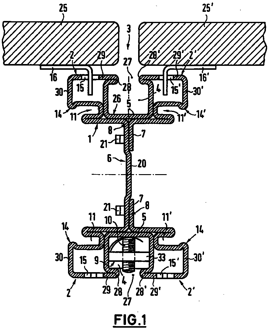
- the support structure shown in Fig. 1 has as one-piece rolled profile formed support profiles 1 Steel sheet on.
- On the support profiles 1 are on both sides separated by a butt joint 3 (only on one side shown) wall shells 25, 25 'by means of mounting elements 16, 16 'releasably attachable.
- a butt joint 3 arranged support profile 1 can additionally Fastening elements 24 for shelves, shelves, cabinet elements, Tables, tabletops and the like by means of Adapter piece 9 are attached.
- Fastening elements 24 for shelves, shelves, cabinet elements, Tables, tabletops and the like by means of Adapter piece 9 are attached.
- Adapter piece 9 are on both sides of the support profile 1 between the respective Holding legs 2, 2 'to the butt joint 3 of the wall shells 25, 25' or the like aligned over the length of the Support profile 1 extending mounting grooves 4 for the Inclusion of the adapter pieces 9 of the fastening elements 24 kept clear.
- the support profile 1 is in the groove bottom 26 of the Fastening groove 4 designed so that a continuous Wall section 5 the profile joint 8 between the web wall 20 and the edge strips 7 covered on the outside.
- the fastening groove 4 is a C-groove with the groove entry slot 27 limiting locking webs 28, 28 'are formed.
- the adapter pieces 9 are in the fastening groove 4 can be fixed by means of clamping screws 10.
- the holding legs 2, 2 ' are the fastening groove 4 box profiles bounding on both sides, the outer Walls 29, 29 'the hanging openings 15, 15' for the Have mounting elements 16, 16 '.
- the mounting elements 16, 16 ' are designed as angle elements, one leg in engage the hanging openings 15, 15 '.
- the intervention openings 15, 15 'for the mounting elements 16, 16' are as from Fig. 3 can be seen, tapered towards its two narrow sides.
- the side walls 30, 30 'of the holding legs 2, 2' are with essentially U-shaped engagement grooves 11, 11 'for the non-positive and / or positive reception of fastening webs 12 a glass holding strip 13, 13 'formed as they is illustrated in more detail in FIG. 9.
- At 2 have the mounting elements 16, 16 'spring sections 19, 19', with the help of which they can be detached in the holding grooves 17, 17 'can be snapped into place.
- the support profile 1 according to FIG. 2 formed in two parts, in such a way that in Groove bottom 26 of the fastening grooves 4 the two wall sections 5, 5 'as end sections of the two profile parts overlap and thereby the profile joint 8 between those in this Fall the web 6 forming two web walls 20, 20 ' cover twice.
- the edge strips 7 for stabilization with one Web wall 20 non-releasably connected by means of overlap 21 are, in the embodiment according to FIG. 2, the two Web walls 20, 20 'secured to one another in this way.
- the profile web 6 has an in modular relation to the hanging openings 15, 15 ' Hole pattern made of interlocking round perforations 22 the for attaching a connecting part (not shown) are provided so that when connecting a vertical with a horizontal support profile fine-tuned height adjustment between those in the vertical Support profile punched-in openings 15, 15 'and Profile axis of the horizontally adjoining support profile results.
- the round perforations combined into a long slot 22 alternate with arranged between them Rectangular openings 23 distributed over the length of the support profile 1 from.
- the adapter pieces 9 consist of a clamping screw 10 with associated lock nut 33 and one on it put on adapter clip 34 with one bent away from it resilient spring arm 35, which after insertion into a fastening groove 4 according to FIGS. 1 and 2 the adapter 9 initially holds in place. Then the clamping screw 10 tightened so that it is supported on the groove base 26, the lock nut 33 moves outwards until it moves in turn on the inner surfaces of the locking webs 28, 28 ' supports, so that the adapter piece 9 simple in this way can be set in the fastening groove 4.
- glass holding strips 13, 13 ' are according to the invention provided glass holding strips 13, 13 ', as they are, for example result from Fig. 9, in the corresponding lateral Eignriffsnuten 11, 11 'engaged and there by means of Locking edges 14, 14 'secured.
- the respective fastening section 12, 12 'of the glass holding strips 13, 13 'equipped with a resilient head which is designed so that it is easy in the engagement grooves 11, 11 'insertable, but only with a larger one Force can be pulled out of these again.
- This serves a locking edge 36, 36 ', which with the locking edges 14, 14 'of the engagement grooves 11, 11' cooperates.
- the Glass holding strips 13, 13 ' are also designed so that they a side arm 37, 37 'on the respective Support the side wall 30, 30 'of the support profile 1 flat. Between the free ends of the glass retaining strips 13, 13 ', 8, glass panes 38, 38 'below Intermediate layer of sealing profiles and spacers can be clamped. To outer grooves 39, 39 'of the glass retaining strips 13, 13' also sealing profiles 40, 40 'can be embedded.
- the glass holding strips 13, 13 ' serve to snap on spring clips 31, 31', as shown in Fig. 11.
- These spring clips 31, 31 ' are with a hook-shaped end 41, 41' in the Hook-in openings 15, 15 'of the holding legs 2, 2' can be hooked in and have at their other end locking tabs 42, 42 'for the Inclusion of locking projections 43, 43 'on the inside of glass frames 32, 32 '.
Landscapes
- Engineering & Computer Science (AREA)
- Architecture (AREA)
- Physics & Mathematics (AREA)
- Electromagnetism (AREA)
- Civil Engineering (AREA)
- Structural Engineering (AREA)
- General Engineering & Computer Science (AREA)
- Mechanical Engineering (AREA)
- Securing Of Glass Panes Or The Like (AREA)
- Vehicle Interior And Exterior Ornaments, Soundproofing, And Insulation (AREA)
- Rod-Shaped Construction Members (AREA)
- Finishing Walls (AREA)
Abstract
Die Erfindung bezieht sich auf eine Tragkonstruktion für
Innenwände, mit vertikalen Tragprofilen (1), an welchen
jeweils durch eine Stoßfuge (3) voneinander getrennte
Wandschalen (25) oder dergleichen mittels Montageelementen
(16) lösbar befestigbar sind, indem das Tragprofil (1) an den
beiden Enden eines von einer Stegwandung (20) mit zwei
endseitig anliegenden Randleisten (7) bzw. zwei aneinanderliegenden
Stegwandungen (20, 20') gebildeten Profilsteges
(6, 7; 20, 20') je nach beiden Seiten von diesem abgebogene
Halteschenkel (2, 2') mit Öffnungen (15, 15') für das
Einhängen der Montageelemente (16, 16') aufweist, wobei an
einem im Bereich einer Stoßfuge (3) der Wandschalen und
dergleichen angeordneten Tragprofil (1) zusätzlich Befestigungselemente
(24) für Fachböden und dergleichen
anbringbar sind, indem auf beiden Seiten des Tragprofils (1)
zwischen den Halteschenkeln (2, 2') eine sich über die Länge
des Trageprofils (1) erstreckende, zu der Stoßfuge (3) der
Wandschalen (25) und dergleichen ausgerichtete Befestigungsnut
(4) für die Aufnahme von Adapterstücken (9) der Befestigungselemente
(24) für die Fachböden und dergleichen freigehalten
sind, und wobei im Nutgrund (26) der Befestigungsnut (24)
wenigstens ein Wandungsabschnitt (5, 5') den Profilstoß (8)
zwischen der Stegwandung (20) und den Randleisten (7) bzw. den
beiden Stegwandungen (20, 20'), welche den Profilsteg (6)
bilden, überdeckt.
Description
Die Erfindung bezieht sich auf eine Tragkonstruktion für Innenwände, insbesondere solche für die raumbegrenzende Unterteilung von Nutzräumen, wie Büroräumen.The invention relates to a supporting structure for Interior walls, especially those for the space-limiting Subdivision of useful spaces, such as office space.
Derartige Innenwände sind dazu bestimmt, Baukonstruktionen in kleinere, jederzeit bedarfsgerecht anpaßbare Nutzungseinheiten zu unterteilen. Dabei werden werksseitig vorgefertigte Bauteile mit geringem Montageaufwand zu einer oberflächenfertigen Innenwand zusammengefügt. Derartige Wandsysteme sollen sich leicht umsetzen und funktionell verändern lassen, wobei bereits vorhandene Bauteile erneut verwendet oder mit zusätzlichen Bauteilen zu weiteren Konfigurationen umgerüstet werden können.Such interior walls are intended to be used in building constructions smaller usage units that can be adapted at any time to divide. In the process, they are prefabricated Components with little assembly effort to a surface-ready Inner wall put together. Such wall systems should be easy to implement and functionally change, already existing components used again or with converted additional components to further configurations can be.
Derartige umsetzbare Innenwände bekannter Art haben eine Metall-Unterkonstruktion mit vertikal und horizontal verlaufenden Trag- und Anschlußprofilen, an welcher ein- oder beidseitig, jeweils durch eine Stoßfuge voneinander getrennte, oberflächenfertige Wandschale, Verglasungsrahmen, Türzargen oder dergleichen mittels Montageelementen lösbar befestigt sind. Das mittig zu einer Stoßfuge angeordnete Tragprofil kann zusätzliche Befesitgungsmöglichkeiten zum Anbringen von Fachböden, Regalen, Schrankelementen, Tafeln, Tischplatten und dergleichen aufweisen. Zur Gewährleistung eines ausreichenden Schall- und Brandschutzes ist der Hohlraum hinter den Wandschalen oder dergleichen meist noch mit Mineralwolle ausgefüllt. Außerdem werden an den Trag- und Anschlußprofilen zusätzlich Abdichtungsmaßnahmen getroffen, wenn erhöhte bauphysikalische Beanspruchungen zu erwarten sind.Such implementable inner walls of a known type have one Metal substructure with vertically and horizontally running Support and connection profiles, on which one or on both sides, each separated by a butt joint, surface-ready wall shell, glazing frame, door frames or the like releasably attached by means of mounting elements are. The support profile arranged in the middle of a butt joint can additional attachment options for attaching Shelves, shelves, cupboard elements, boards, table tops and the like. To ensure adequate Sound and fire protection is the cavity behind the Wall bowls or the like mostly with mineral wool filled out. In addition, on the support and connection profiles additional sealing measures are taken if increased physical loads are to be expected.
Aus der DE 37 26 255 A1 ist beispielsweise eine als Trennwand bezeichnete umsetzbare Innenwand bekannt, bei welcher das als Profilständer bezeichnete vertikale Tragprofil als einstückiges Walzprofil aus Stahlblech ausgebildet ist, das im wesentlichen die Gestalt eines Doppel-T-Profils aufweist, dessen Halteschenkel durch eine jeweils zwischen ihnen angeordnete Hohlkammerbegrenzungswand paarweise einstückig miteinander verbunden sind. Von den Halteschenkeln sind weitere Hohlraumbegrenzungswände abgebogen. Zwei der zu einander gegenüberliegenden Halteschenkeln gehörenden Begrenzungswände sind dabei, unter Bildung des Verbindungsstegs, einstückig miteinander verbunden, während die zu den beiden anderen Halteschenkeln gehörenden Begrezungswände eine freie, gegen die benachbarte (beispielsweise den Verbindungssteg bildende) Begrenzungswand anliegende Randleiste aufweisen.DE 37 26 255 A1, for example, describes a partition designated implementable inner wall is known, in which the as Profile stand referred to vertical support profile as one piece Rolled profile is made of sheet steel, which in essentially has the shape of a double-T profile, whose holding leg by one between each arranged cavity wall in one piece are interconnected. Of the holding legs are further cavity boundary walls bent. Two of the too mutually opposite holding legs Boundary walls are here, forming the connecting web, integrally connected to one another, while the to two other holding legs have a wall free, against the neighboring one (e.g. the connecting bridge forming) border wall have adjacent edge strip.
Bei einer ersten Ausführungsform dieser umsetzbaren Innenwand erstreckt sich die Hohlkammer über einen Teil der Gesamtbreite der miteinander verbundenen Halteschenkel, während sich die Hohlkammer bei einer anderen Ausführungsform über die gesamte Breite der verbundenen Halteschenkel erstreckt, so daß die nach innen gebogenen Blechstreifen die rückwärtige Begrenzungswand der Hohlkammer bilden. Bei der bekannten umsetzbaren Innenwand sind in den Verbindungssteg des Tragprofils zusätzlich Durchgangslöcher für Montagezwecke in bekannter Weise eingestanzt.In a first embodiment of this convertible inner wall the hollow chamber extends over part of the total width the interconnected holding leg, while the Hollow chamber in another embodiment over the entire Width of the connected holding legs extends so that the the rear boundary wall form the hollow chamber. With the known implementable inner wall are in the connecting web of the Support profile additional through holes for assembly purposes in stamped in a known manner.
Bei dem Profilständer nach der DE 37 26 255 A1 soll gegenüber
den aus der DE 32 25 060 A1 und der US 2 633 945 A bekannten
Profilständern die Schall- und Branddämmung verbessert werden,
was jedoch, wie sich in der Praxis gezeigt hat, nicht der Fall
ist. Sowohl nach der DE 32 25 060 A1 als auch nach der US 2
633 945 A wird vorgeschlagen, die Verbindungsstege der aus
drei bzw. zwei Einzelstäben zusammengesetzten Tragprofile
durch Verstanzen oder durch Punktschweißen miteinander fest
und dicht anliegend zu verbinden. Nach der in der DE 37 26 255
A1 gezeigten Tragprofilausbildung ist keine derartige
Verbindung zwischen dem Verbindungssteg und den an diesem frei
anliegenden Randleisten vorgesehen. Dies hat zur Folge, daß
der über die Stoßfugen zwischen Wandschalen und dergleichen
durch Rasteröffnungen in den die Halteschenkel des Tragprofils
verbindenen Hohlkammerbegrenzungswände eintretende Luftschall
durch die in der gesamten Profillänge verlaufenden Spalten
zwischen dem Verbindungssteg und den an diesem frei anliegenden
Randleisten praktisch ungehindert hindurchgeleitet wird.
Es ist darüber hinaus durch entsprechende Brandversuche
bekannt, daß sich die Tragprofile bei einer einseitigen
Brandbeanspruchung zum Feuer hin durchbiegen, wobei durch
ungleichmäßige Erwärmung hervorgerufene Profilverformungen auf
der dem Feuer gegenüberliegenden Randseite die mögliche
Spaltbildung zwischen dem Verbindungssteg und der freien
Randleiste derart ungünstig beeinflussen, daß ein Durchtritt
des Feuers nicht ausgeschlossen werden kann. Ein Vergleich mit
den Lösungen nach der US 2 633 945 A und DE 32 25 060 A1
zeigt, daß die Profilkonstruktion nach der DE 37 26 255 A1
tatsächlich schlechter ist. Auch die nach der DE 38 21 500 A1
zusätzlich vorgeschlagene Maßnahme, die Randleisten mit dem
Verbindungssteg durch formgleich ineinandergreifende Formstanzungen
miteinander zu verbinden, ergibt sich eine nur
unzureichende Verbesserung bei Schall- und Brandbeanspruchungen
wegen der freien Zugänglichkeit der Profilfuge zwischen
den Profilabschnitten im Stoßbereich der Wandelemente. Darüber
hinaus haftet der aus der DE 37 26 255 A1 bekannten Profilkonstruktion,
bei welcher in die Halteschenkel sowohl Einhängeöffnungen
für Wandschalen und dergleichen als auch Rasteröffnungen
im Bereich der Stoßfuge zwischen diesen zum Anbringen
von Fachböden und dergleichen vorgesehen sind, der Nachteil
an, daß die Zuordnungs- und Montagemöglichkeiten begrenzt
sind, so daß diese den heutigen Forderungen nach einer
individuellen Wandschalen- und Glasflächengestaltung nicht
mehr entsprechen.In the profile stand according to DE 37 26 255 A1 opposite
those known from
Die bei bekannten umsetzbaren Innenwänden bisher vorgesehenen Verglasungen sind in der Regel wenig montagefreundlich, bzw. ist der Glasein- und -ausbau nur bei einer unvollständig montierten Wand möglich. Ähnliche Probleme ergeben sich beim Ein-, Aus- und Umbauen von Türzargen und Türelementen. Auch hier erfolgt die Montage meist mit dem Wandaufbau, so daß spätere Änderungen in der Regel eine Teildemontage der fertigen Innenwand erfordern.The previously provided for known implementable inner walls Glazing is generally not very easy to install, or the glass installation and removal is only incomplete with one mounted wall possible. Similar problems arise with Installation, removal and conversion of door frames and door elements. Also here the assembly is usually done with the wall structure, so that later changes usually a partial disassembly of the finished interior wall require.
Der Erfindung liegt die Aufgabe zugrunde, eine Tragkonstruktion hinsichtlich der Schall- und Branddämmung zu verbessern. Die Anbringungsmöglichkeiten für Befestigungsteile im Bereich der Stoßfuge zwischen den Wandschalen und dergleichen sowie für die Wandschalen und dergleichen sollen sowohl funktionell als auch ästhetisch verbessert werden. Die Befestigungs- und Montageöffnungen sind so zu gestalten und anzuordnen, daß eine individuelle Anpassung der umsetzbaren Innenwand an die heutigen Forderungen entsprechende Wand- und Glasflächengestaltung ohne Nachteile für eine weitgehende werkseitige Vorfertigung und unter Berücksichtigung eines ausreichenden Ausgleichs bauüblicher Maßtoleranzen gewährleistet ist. Hinsichtlich einer weiteren Reduzierung der Montagezeiten am Bau soll sich außerdem eine Verbesserung insbesondere beim Einbau von Verglasungen dahingehend ergeben, daß ein einfacher, werkzeugfreier Glasein- und -ausbau möglich ist, wobei Normalverglasungen jeweils in Brandschutzverglasungen umrüstbar sind. The invention has for its object a support structure in terms of sound and fire insulation improve. The attachment options for fasteners in the area of the butt joint between the wall shells and the like as well as for the wall shells and the like be improved both functionally and aesthetically. The Fastening and assembly openings are to be designed and to order that an individual adaptation of the implementable Interior wall to meet today's requirements wall and Glass surface design without disadvantages for extensive factory prefabrication and taking into account a Sufficient compensation of customary dimensional tolerances guaranteed is. Regarding a further reduction in Assembly times on construction should also be an improvement in particular when installing glazing, that simple, tool-free glass installation and removal is possible is, with normal glazing in fire protection glazing are convertible.
Die zuvor beschriebenen Ziele werden erfindungsgemäß erreicht bei einer Tragkonstruktion für Innenwände der eingangs genannten Art, mit vertikalen als ein- oder zweiteiliges Walzprofil ausgebildeten Tragprofilen aus Stahlblech, an welchen ein- oder beidseitig jeweils durch eine Stoßfuge voneinander getrennte Wandschalen, Verglasungsrahmen, Türzargen oder dergleichen mittels Montageelementen lösbar befestigbar sind, indem das Tragprofil an den beiden Enden eines von einer Stegwandung mit zwei endseitig anliegenden Randleisten bzw. zwei aneinanderliegenden Stegwandungen gebildeten Profilsteges je nach beiden Seiten von diesem abgebogene Halteschenkel mit Öffnungen für das Einhängen von Montageelementen aufweist, wobei an einem im Bereich einer Stoßfuge der Wandschalen und dergleichen angeordneten Tragprofil zusätzlich Befestigungselemente für Fachböden, Regale, Schrankelemente, Tafeln, Tischbplatten und dergleichen anbringbar sind, indem auf beiden Seiten des Tragprofils zwischen den Halteschenkeln eine zu der Stoßfuge der Wandschalen und dergleichen ausgerichtete, sich über die Länge des Tragprofils erstreckende Befestigungsnut für die Aufnahme von Adapterstücken der Befestigungselemente für die Fachböden und dergleichen freigehalten sind, und wobei im Nutgrund der Befestigungsnut wenigstens ein Wandungsabschnitt den Profilstoß zwischen der Stegwandung und den Randleisten bzw. den beiden Stegwandungen, welche den Profilsteg bilden, überdeckt.The objectives described above are achieved according to the invention in the case of a supporting structure for the interior walls of the entrance mentioned type, with vertical as one or two parts Rolled profile formed support profiles made of sheet steel which one or both sides by a butt joint separate wall shells, glazing frames, Door frames or the like can be detached by means of mounting elements are attachable by the support profile at the two ends one of a web wall with two adjoining ends Sidebars or two adjacent web walls formed profile web depending on both sides of this bent holding leg with openings for hanging Has mounting elements, one in the area of a Butt joint of the wall shells and the like arranged Support profile additional fastening elements for shelves, Shelves, cupboard elements, boards, table tops and the like are attachable by both sides of the support profile between the holding legs one to the butt joint of the wall shells and the like aligned over the length of the Carrying profile extending fastening groove for receiving Adapter pieces of the fasteners for the shelves and the like are kept free, and being in the bottom of the groove Fastening groove at least one wall section the profile joint between the web wall and the edge strips or two web walls, which form the profile web, covered.
Hierdurch ergibt sich unter anderem eine wesentliche Verbesserung des Schall- und Brandschutzes, weil gegenüber dem Stand der Technik durch Schließen des Verbindungsstoßes zwischen der Stegwandung des Tragprofils und den freien Randleisten bzw. zweier Stegwandungen mittels der am Nutgrund der Befestigungsnut angeordneten Wandungsabschnitte ein flächenschließender Effekt erreicht wird, welcher gegeben ist, wenn ein einfaches Walzprofil ohne jegliche Öffnungen zum Einhängen von Wandschalen, Anbringen von Regalen oder dergleichen, wie dies beispielsweise aus der FR 83 12 424 B1 bekannt ist, als Tragprofil verwendet würde.Among other things, this results in a significant improvement of noise and fire protection, because compared to that State of the art by closing the connection joint between the web wall of the support profile and the free Edge strips or two web walls by means of the on the groove base the fastening groove arranged wall sections surface-closing effect is achieved, which is given if a simple rolled profile without any openings for Hang wall scales, attach shelves or the like, as for example from FR 83 12 424 B1 is known would be used as a support profile.
In weiterer Ausgestaltung der Erfindung kann die Befestigungsnut als C-Nut mit den Nuteintrittsschlitz begrenzenden Arretierungsstegen ausgebildet sein, so daß Adapterstücke der Befestigungselemente für die Anbringung von Fachböden und dergleichen im Stoßfugenbereich einfach möglich ist.In a further embodiment of the invention, the mounting groove as a C-groove with the slot entry slot Locking bars should be designed so that adapter pieces of Fasteners for attaching shelves and the like is easily possible in the butt joint area.
Zu diesem Zweck können die Adapterstücke in den Befestigungsnuten, beispielsweise mittels Klemmschrauben, festlegbar sein.For this purpose, the adapter pieces in the fastening grooves, for example, by means of clamping screws.
Für eine Stabilisierung des Tragprofils, insbesondere im Bereich der Kräfte aufnehmenden Befestigungsnut, ist es von Vorteil, wenn die Halteschenkel als die Befestigungsnut beidseits begrenzende Kastenprofile ausgebildet sind, deren äußere Wandungen die Einhängeöffnungen für die Montageelemente aufweisen. Die Montageelemente der Wandschalen und dergleichen sind dabei den anzuhängenden Wandschalen und dergleichen so zugeordnet, daß nach der Montage die Einhängeöffnungen von den Wandschalen und dergleichen, aus Brand- und Schallschutzgründen abgedeckt sind.For stabilizing the support profile, especially in Range of the force-absorbing fastening groove, it is from Advantage if the holding leg as the fastening groove box profiles are formed on both sides, the outer walls the hanging openings for the mounting elements exhibit. The mounting elements of the wall shells and the like are the wall shells to be attached and the like assigned that after mounting the hanging openings of the Wall shells and the like, for fire and noise protection reasons are covered.
Von besonderem Vorteil ist es, wenn gemäß einer noch weiteren Ausgestaltung der Erfindung die Seitenwandungen der Halteschenkel mit im wesentlichen U-förmigen Eingriffsnuten für die kraft- und/oder formschlüssige Aufnahme von Befestigungsstegen einer Glashalteleiste ausgebildet sind. Die so an den Seitenflächen der Halteschenkel des Tragprofils ausgeformten U-förmigen Nutausbildungen ermöglichen die schraubenlose Befestigung von Glashalteleisten, wodurch die Verglasung derartiger Wände wesentlich vereinfacht ist.It is particularly advantageous if according to another Embodiment of the invention, the side walls of the holding legs with essentially U-shaped engagement grooves for the non-positive and / or positive reception of fastening webs a glass retaining bar are formed. The so on Shaped side surfaces of the support legs of the support profile U-shaped groove designs enable screwless Attachment of glass retaining strips, which makes the glazing such walls is significantly simplified.
Dabei können die Befestigungsstege der Glashalteleisten und dadurch die Glashalteleisten selbst mittels in dem Nutauslauf der Eingriffsnuten ausgebildeter Arretierungskanten gesichert sein.The attachment bars of the glass holding strips and thereby the glass retaining strips themselves by means of the slot outlet the engagement grooves of trained locking edges secured be.
Einen festen Sitz erhalten die in die Einhängeöffnungen eingreifenden Montageelemente der Wandschalen und dergleichen, wenn erstere zu ihren beiden oberen und unteren Schmalseiten hin verjüngt sind.They get a tight fit in the hanging openings engaging mounting elements of the wall shells and the like, if the former to their two upper and lower narrow sides are tapered.
Es ist aber auch möglich, daß die Einhängeöffnungen für die Montageelemente der Wandschalen und dergleichen als sich über die Länge des Tragprofils erstreckende Haltenuten ausgebildet sind.But it is also possible that the suspension openings for the Mounting elements of the wall shells and the like as themselves the length of the support profile extending retaining grooves are.
Die Haltenuten können dabei vorzugsweise als zum Beispiel asymetrische C-Nuten mit wenigstens einem Arretierungssteg am Nutenauslauf ausgebildet sein, um eine zusätzliche Sicherung für die Montageelemente zu bilden. Für diesen Fall können die Montageelemente der Wandschalen und dergleichen beispielsweise mittels Federabschnitten lösbar in die Haltenuten einrastbar sein.The holding grooves can preferably be, for example asymmetrical C-slots with at least one locking bar on Groove outlet should be designed to provide additional security to form for the mounting elements. In this case, the Mounting elements of the wall shells and the like, for example detachably snap-fit into the retaining grooves by means of spring sections be.
Zur Stabilisierung des Tragprofilaufbaus kann es von Vorteil sein, wenn die Stegwandung mit den Randleisten bzw. mit der weiteren Stegwandung durch Stechen mit vorzugsweise beidseitiger Verlappung nicht-lösbar verbunden sind.It can be an advantage to stabilize the supporting profile structure be when the web wall with the edge strips or with the further web wall by lancing, preferably on both sides Lapping are non-releasably connected.
Für die Horizontalverbindung der Tragprofile weist deren Profilsteg vorzugsweise ein im modularen Bezug zu den Einhängeöffnungen stehendes Lochbild aus langschlitzförmig ineinadergreifenden Rundlochungen auf, zwischen welchen vorzugsweise Rechtecköffnungen über die Länge des Tragprofils verteilt angeordnet sind. Durch diese Steglochung ist eine sehr feinstufige Maßanpassung an alle heutigen Forderungen nach individueller Wand- und Glasflächenaufteilung entsprochen. For the horizontal connection of the support profiles has their Profile web preferably a modular reference to the Perforated hole pattern made of elongated slots interlocking round perforations, between which preferably rectangular openings along the length of the support profile are distributed. Through this hole in the bridge there is one very fine adjustment to all today's requirements according to individual wall and glass surface division.
Erfindungsgemäß kann ferner eine Federklammer vorgesehen sein, welche in eine Einhängeöffnung einhängbar und auf eine Glashalteleiste aufklipsbar ist und welche Mittel zum Einrasten eines Glasrahmens aufweist. Hierdurch ist eine einfache Montagemöglickeit für im Bedarfsfall vorzusehende Glasrahmen geschaffen.According to the invention, a spring clip can also be provided which can be hooked into a hanging opening and onto a Glass holding bar can be clipped on and what means for Has snapping a glass frame. This is one simple assembly possibility for to be provided if necessary Glass frames created.
Die Erfindung bezieht sich ferner auf ein Adapterstück mit den
Merkmalen der Ansprüche 15 und 16.The invention further relates to an adapter piece with the
Features of
Weitere Ziele, Merkmale, Vorteile und Anwendungsmöglichkeiten der Erfindung ergeben sich aus der nachfolgenden Beschreibung von Ausführungsbeispielen anhand der Zeichnung. Dabei bilden alle beschriebenen und/oder bildlich dargestellten Merkmale für sich oder in beliebiger Kombination den Gegenstand der Erfindung, auch unabhängig von ihrer Zusammenfassung in einzelnen Ansprüchen oder deren Rückbeziehung.Further goals, features, advantages and possible applications the invention result from the following description of exemplary embodiments with reference to the drawing. In doing so all described and / or illustrated features for itself or in any combination the subject of Invention, regardless of its summary in individual claims or their relationship.
Es zeigen:
- Fig. 1
- einen Horizontalschnitt einer Tragkonstruktion für umsetzbare Innenwände nach einem Ausführungsbeispiel der Erfindung,
- Fig. 2
- einen Horizontalschnitt entsprechend Fig. 1 für eine andere Ausführungsform der Erfindung,
- Fig. 3
- ein erfindungsgemäßes Tragprofil in stirnseitiger Ansicht,
- Fig. 4
- ein erfindungsgemäßes Tragprofil in Seitenansicht,
- Fig. 5
- teilweise geschnitten ein erfindungsgemäßes Adapterstück von Befestigungselementen für Fachböden und dergleichen im Stoßfugenbereich der Innenwand,
- Fig. 6a und 6b
- in Seitenansicht und in Draufsicht eine Art der Anbringung von Befestigungselementen im Stoßfugenbereich der Innenwand mittels Adapterstück,
- Fig. 7
- die Möglichkeit einer Anhängung von Konsolen und dergleichen in den Einhängeöffnungen der Halteschenkel eines erfindungsgemäßen Tragprofils,
- Fig. 8
- im Horizontalschnitt eine weitere Ausgestaltung einer erfindungsgemäßen Tragkonstruktion,
- Fig. 9
- eine Glashalterleiste zur Verwendung mit einem erfindungsgemäßen Tragprofil,
- Fig. 10
- im Horizontalschnitt eine noch weitere Ausgestaltung einer erfindungsgemäßen Tragkonstruktion, und
- Fig. 11
- eine Federklammer zur Verwendung bei erfindungsgemäßen Tragprofilen für die Befestigung von Glasrahmen.
- Fig. 1
- 2 shows a horizontal section of a support structure for implementable inner walls according to an embodiment of the invention,
- Fig. 2
- 2 shows a horizontal section corresponding to FIG. 1 for another embodiment of the invention,
- Fig. 3
- a support profile according to the invention in frontal view,
- Fig. 4
- a support profile according to the invention in side view,
- Fig. 5
- partially cut an adapter piece according to the invention of fastening elements for shelves and the like in the butt joint area of the inner wall,
- 6a and 6b
- a side view and a top view of a type of attachment of fastening elements in the butt joint area of the inner wall by means of an adapter piece,
- Fig. 7
- the possibility of attaching brackets and the like in the hanging openings of the holding legs of a support profile according to the invention,
- Fig. 8
- in a horizontal section a further embodiment of a supporting structure according to the invention,
- Fig. 9
- a glass holder strip for use with a support profile according to the invention,
- Fig. 10
- in horizontal section a still further embodiment of a support structure according to the invention, and
- Fig. 11
- a spring clip for use in support profiles according to the invention for the attachment of glass frames.
Die in Fig. 1 dargestellte Tragkonstruktion weist als
einteiliges Walzprofil ausgebildete Tragprofile 1 aus
Stahlblech auf. An den Tragprofilen 1 sind beidseitig jeweils
durch eine Stoßfuge 3 voneinander getrennte (nur einseitig
dargestellte) Wandschalen 25, 25' mittels Montageelementen 16,
16' lösbar befestigbar. Zu diesem Zweck weist das Tragprofil
1 an den beiden Enden eines von einer Stegwandung 20 und zwei
endseitig anliegenden Randleisten 7 gebildeten Profilstegs 6
je nach beiden Seiten von diesem abgebogene Halteschenkel 2,
2' mit nach außen weisenden Öffnungen 15, 15' für das
Einhängen der Montageelemente 16, 16' auf. An einem im Bereich
einer Stoßfuge 3 angeordneten Tragprofil 1 können zusätzlich
Befestigungselemente 24 für Fachböden, Regale, Schrankelemente,
Tafeln, Tischplatten und dergleichen mittels
Adapterstück 9 angebracht werden. Zu diesem Zweck sind auf
beiden Seiten des Tragprofils 1 zwischen den jeweiligen
Halteschenkeln 2, 2' zu der Stoßfuge 3 der Wandschalen 25, 25'
oder dergleichen ausgerichtete, sich über die Länge des
Tragprofils 1 erstreckende Befestigungsnuten 4 für die
Aufnahme der Adapterstücken 9 der Befestigungselemente 24
freigehalten. Das Tragprofil 1 ist im Nutgrund 26 der
Befestigungsnut 4 so gestaltet, daß ein durchgehender
Wandungsabschnitt 5 den Profilstoß 8 zwischen der Stegwandung
20 und den Randleisten 7 außen überdeckt.The support structure shown in Fig. 1 has as
one-piece rolled profile formed
Die Befestigungsnut 4 ist als C-Nut mit den Nuteintrittsschlitz
27 begrenzenden Arretierungsstegen 28, 28' ausgebildet.
Die Adapterstücke 9 sind in der Befestigungsnut 4
mittels Klemmschrauben 10 festlegbar.The
Die Halteschenkel 2, 2' sind als die Befestigungsnut 4
beidseits begrenzende Kastenprofile ausgebildet, deren äußere
Wandungen 29, 29' die Einhängeöffnungen 15, 15' für die
Montageelemente 16, 16' aufweisen. Die Montageelemente 16, 16'
sind als Winkelelemente ausgebildet, deren einer Schenkel in
die Einhängeöffnungen 15, 15' eingreifen. Die Eingriffsöffnungen
15, 15' für die Montageelemente 16, 16' sind, wie aus
Fig. 3 ersichtlich, zu ihren beiden Schmalseiten hin verjüngt.The holding
Die Seitenwandungen 30, 30' der Halteschenkel 2, 2' sind mit
im wesentlichen U-förmige Eingriffsnuten 11, 11' für die
kraft- und/oder formschlüssige Aufnahme von Befestigungsstegen
12 einer Glashalteleiste 13, 13' ausgebildet, wie sie
in Fig. 9 näher veranschaulicht ist. Die Befestigungsstege 12
und dadurch die Glashalteleisten 13, 13' sind mittels in dem
Nutauslauf der Eingriffsnuten 11, 11' ausgebildeter Arretierungskanten
14, 14' gesichert. The
Wie anhand des Ausführungsbeispieles von Fig. 2 gezeigt,
können die einzelnen Einhängeöffnungen 15, 15' für die
Montageelemenete 16, 16' auch als sich über die Länge des
Tragprofils 1 erstreckende Haltenuten 17, 17' ausgebildet
sein. Die Haltenuten 17, 17' haben in dem in Fig. 2 veranschaulichten
Ausführungsbeispiel die Form asymetrischer C-Nuten
mit einem Arretierungssteg 18, 18' am Nutauslauf. Bei
der Ausführungsform gemäß Fig. 2 haben die Montageelemente 16,
16' Federabschnitte 19, 19', mit Hilfe welcher sie lösbar in
die Haltenuten 17, 17' einrastbar sind.As shown in the embodiment of FIG. 2,
can the
Abweichend von Fig. 1 ist das Tragprofil 1 gemäß Fig. 2
zweiteilig ausgebildet, und zwar in der Weise, daß sich im
Nutgrund 26 der Befestigungsnuten 4 die beiden Wandungsabschnitte
5, 5' als Endabschnitte der beiden Profilteile
überlappen und dadurch den Profilstoß 8 zwischen den in diesem
Fall den Profilsteg 6 bildenden beiden Stegwandungen 20, 20'
doppelt abdecken. Ebenso wie bei der Ausführungsform gemäß
Fig. 1 die Randleisten 7 zur Stabilisierung mit der einen
Stegwandung 20 durch Verlappung 21 nicht-lösbar verbunden
sind, sind bei der Ausführungsform gemäß Fig. 2 die beiden
Stegwandungen 20, 20' auf diese Weise aneinander gesichert.1 is the
Wie sich aus Fig. 4 ergibt, hat der Profilsteg 6 ein in
modularem Bezug zu den Einhängeöffnungen 15, 15' stehendes
Lochbild aus langschlitzförmig ineinandergreifenden Rundlochungen
22 die zur Anbringung eines Verbindungsteils (nicht
gezeigt) vorgesehen sind, so daß sich beim Verbinden eines
vertikalen mit einem horizontal verlaufenden Tragprofil eine
feinstufige Höhenanpassung zwischen den in dem vertikalen
Tragprofil eingestanzten Einhängeöffnungen 15, 15' und der
Profilachse des horizontal daran anschließenden Tragprofils
ergibt. Die zu einem Langschlitz zusammengefaßten Rundlochungen
22 wechseln sich mit zwischen diesen angeordneten
Rechtecköffnungen 23 über die Länge des Tragprofils 1 verteilt
ab.As can be seen from Fig. 4, the
Die Adapterstücke 9 bestehen gemäß Fig. 5 aus einer Klemmschraube
10 mit zugehöriger Klemmutter 33 und einem darauf
aufgesetzen Adapterklip 34 mit einem davon gebogen wegragenden
elastisch nachgiebigen Federarm 35, welcher nach dem Einfügen
in eine Befestigungsnut 4 gemäß Fig. 1 und 2 den Adapter 9
zunächst in Position hält. Wird dann die Klemmschraube 10
angezogen, so daß sie sich auf dem Nutgrund 26 abstützt,
bewegt sich die Klemmutter 33 nach außen bis sie sich
ihrerseits auf den Innenflächen der Arretierungsstege 28, 28'
abstützt, so daß das Adapterstück 9 auf diese Weise einfach
in der Befestigungnsut 4 festgelegt werden kann.5, the
Bei der Ausgestaltung gemäß Fig. 8 sind die erfindungsgemäß
vorgesehenen Glashalteleisten 13, 13', wie sie sich beispielsweise
aus Fig. 9 ergeben, in die entsprechenden seitlichen
Eignriffsnuten 11, 11' eingerastet und dort mittels der
Arretierungskanten 14, 14' gesichert. Zu diesem Zweck ist der
jeweilige Befestigungsabschnitt 12, 12' der Glashalteleisten
13, 13' mit einem federnd nachgiebigen Kopf ausgestattet,
welcher so gestaltet ist, daß er zwar einfach in die Eingriffsnuten
11, 11' einführbar, aber nur mit größerem
Kraftaufwand wieder aus diesen herausziehbar ist. Hierzu dient
eine Arretierungskante 36, 36', welche mit den Arretierungskanten
14, 14' der Eingriffsnuten 11, 11' zusammenwirkt. Die
Glashalteleisten 13, 13' sind ferner so ausgestaltet, daß sie
sich über einen seitlichen Arm 37, 37' an der jeweiligen
Seitenwandung 30, 30' des Tragprofils 1 flächig abstützen.
Zwischen den freien Enden der Glashalteleisten 13, 13' sind,
wie aus Fig. 8 ersichtlich, Glasscheiben 38, 38' unter
Zwischenlage von Dichtprofilen und Abstandshaltern einspannbar.
Zu Außennuten 39, 39' der Glashalteleisten 13, 13' können
ferner Dichtprofile 40, 40' eingelassen sein. 8 are according to the invention
provided glass holding strips 13, 13 ', as they are, for example
result from Fig. 9, in the corresponding
Wie aus Fig. 10 ersichtlich, können die Glashalteleisten 13,
13' zusätzlich dem Aufrasten von Federklammern 31, 31' dienen,
wie sie in Fig. 11 dargestellt sind. Diese Federklammern 31,
31' sind mit ihrem einen hakenförmigen Ende 41, 41' in die
Einhängeöffnungen 15, 15' der Halteschenkel 2, 2' einhängbar
und weisen an ihrem anderen Ende Rastlaschen 42, 42' für die
Aufnahme von Arretierungsvorsprüngen 43, 43' auf der Innenseite
von Glasrahmen 32, 32' auf. Die Glasrahmen 32, 32' können
sich gemäß Fig. 10 einerseits an den äußeren Wandungen 29, 29'
der Halteschenkel 2, 2' und andererseits über Dichtprofile auf
der Außenseite der Glasscheiben 38, 38' abstützen. As can be seen from FIG. 10, the glass holding strips 13,
13 'additionally serve to snap on spring clips 31, 31',
as shown in Fig. 11. These spring clips 31,
31 'are with a hook-shaped end 41, 41' in the
Hook-in
- 11
- TragprofilSupport profile
- 2, 2'2, 2 '
- HalteschenkelHolding leg
- 33rd
- StoßfugeButt joint
- 44th
- BefestigungsnutMounting groove
- 5, 5'5, 5 '
- WandungsabschnitteWall sections
- 66
- ProfilstegProfile web
- 77
- RandleistenSidebars
- 88th
- ProfilstoßProfile joint
- 99
- AdapterstückAdapter piece
- 1010th
- KlemmschraubeClamping screw
- 11, 11'11, 11 '
- EingriffsnutenEngagement grooves
- 12, 12'12, 12 '
- BefestigungsabschnitteFastening sections
- 13, 13'13, 13 '
- GlashalteleistenGlass holding strips
- 14, 14'14, 14 '
- ArretierungskantenLocking edges
- 15, 15'15, 15 '
- Öffnungenopenings
- 16, 16'16, 16 '
- MontageelementeAssembly elements
- 17, 17'17, 17 '
- NutenGrooves
- 18, 18'18, 18 '
- ArretierungsstegeLocking bars
- 19, 19'19, 19 '
- FederabschnitteSpring sections
- 20, 20'20, 20 '
- StegwandungenWeb walls
- 2121
- VerlappungenOverlaps
- 2222
- RundlochungenRound perforations
- 2323
- Öffnungenopenings
- 2424th
- BefestigungselementeFasteners
- 25, 25'25, 25 '
- Wandschalen und dergleichenWall cups and the like
- 2626
- NutgrundGroove base
- 2727
- NuteintrittsschlitzSlot entry slot
- 28, 28'28, 28 '
- ArretierungsstegeLocking bars
- 29, 29'29, 29 '
- äußere Wandungenouter walls
- 30, 30'30, 30 '
- SeitenwandungenSide walls
- 31, 31'31, 31 '
- Federklammern Spring clips
- 32, 32'32, 32 '
- GlasrahmenGlass frame
- 3333
- KlemmutterClamping nut
- 3434
- AdapterklipAdapter clip
- 3535
- FederarmSpring arm
- 36, 36'36, 36 '
- ArretierungskantenLocking edges
- 37, 37'37, 37 '
- Armepoor
- 38, 38'38, 38 '
- GlasscheibenPanes of glass
- 39, 39'39, 39 '
- AußennutenExternal grooves
- 40, 40'40, 40 '
- DichtprofileSealing profiles
- 41, 41'41, 41 '
- hakenförmiges Endehook-shaped end
- 42, 42'42, 42 '
- RastlaschenLocking tabs
- 43, 43'43, 43 '
- ArretierungsvorsprüngeLocking projections
Claims (16)
Applications Claiming Priority (2)
| Application Number | Priority Date | Filing Date | Title |
|---|---|---|---|
| DE29706302U DE29706302U1 (en) | 1997-04-09 | 1997-04-09 | Support structure for interior walls |
| DE29706302U | 1997-04-09 |
Publications (3)
| Publication Number | Publication Date |
|---|---|
| EP0870880A2 true EP0870880A2 (en) | 1998-10-14 |
| EP0870880A3 EP0870880A3 (en) | 1999-05-19 |
| EP0870880B1 EP0870880B1 (en) | 2003-07-09 |
Family
ID=8038657
Family Applications (1)
| Application Number | Title | Priority Date | Filing Date |
|---|---|---|---|
| EP98101678A Expired - Lifetime EP0870880B1 (en) | 1997-04-09 | 1998-01-31 | Support structure for partition walls |
Country Status (3)
| Country | Link |
|---|---|
| EP (1) | EP0870880B1 (en) |
| AT (1) | ATE244800T1 (en) |
| DE (2) | DE29706302U1 (en) |
Cited By (2)
| Publication number | Priority date | Publication date | Assignee | Title |
|---|---|---|---|---|
| WO2002036480A1 (en) * | 2000-11-04 | 2002-05-10 | Krones Ag | Machine protection device |
| ES2170631A1 (en) * | 2000-01-11 | 2002-08-01 | Kemen Com S A Soc Unipersonal | System for the construction of partitions to compartmentalise workspaces |
Families Citing this family (6)
| Publication number | Priority date | Publication date | Assignee | Title |
|---|---|---|---|---|
| DE29812527U1 (en) | 1998-07-14 | 1999-01-28 | Mäder GmbH Schrank- und Trennwandsysteme, 72280 Dornstetten | Profile post |
| CN1838901A (en) * | 2003-08-22 | 2006-09-27 | 拉多斯劳·拉索塔 | Composite |
| DE202009006181U1 (en) * | 2009-05-01 | 2009-07-16 | Schletter Gmbh | Structure |
| US8209917B1 (en) * | 2009-05-14 | 2012-07-03 | DeZaio Productions, Inc. | Temporary, non-load bearing wall assembly |
| CN110029755B (en) * | 2019-04-26 | 2024-11-08 | 湖南坚致幕墙安装设计有限公司 | A modular frame system |
| CN110029756B (en) * | 2019-04-26 | 2024-11-12 | 湖南坚致幕墙安装设计有限公司 | Modular frame system |
Family Cites Families (7)
| Publication number | Priority date | Publication date | Assignee | Title |
|---|---|---|---|---|
| FR2376927A1 (en) * | 1977-01-06 | 1978-08-04 | Diffusion Materiel Stockage | H=section mullion for releasable mounting of glazed panels - has sub-flanges and houses clips retaining panel ends and masking strips |
| US4441300A (en) * | 1978-08-14 | 1984-04-10 | Crown Metal Manufacturing Company | Bracket support for wall studs |
| DE3726255C2 (en) * | 1986-10-18 | 1994-03-10 | Straehle Raum Systeme Gmbh | partition wall |
| DE3825566A1 (en) * | 1988-07-28 | 1990-02-01 | Plan Object Gmbh | Profile combination for uprights and transoms of the substructure of a partition wall |
| NL8801950A (en) * | 1988-08-04 | 1990-03-01 | Sypla Systeem Planning B V | Partition-supporting structure - has column of plate material bent along lengthwise edge to form recess |
| DE3835501A1 (en) * | 1988-10-19 | 1990-05-03 | Ver Spezialmoebel Verwalt | PARTITION UNIT |
| FR2746125A1 (en) * | 1996-03-13 | 1997-09-19 | Mosaiques | ASSEMBLY FOR FASTENING AND ASSEMBLING FACING PANELS AND REMOVABLE PARTITION COMPRISING SUCH AN ASSEMBLY |
-
1997
- 1997-04-09 DE DE29706302U patent/DE29706302U1/en not_active Expired - Lifetime
-
1998
- 1998-01-31 EP EP98101678A patent/EP0870880B1/en not_active Expired - Lifetime
- 1998-01-31 DE DE59808944T patent/DE59808944D1/en not_active Expired - Fee Related
- 1998-01-31 AT AT98101678T patent/ATE244800T1/en not_active IP Right Cessation
Cited By (3)
| Publication number | Priority date | Publication date | Assignee | Title |
|---|---|---|---|---|
| ES2170631A1 (en) * | 2000-01-11 | 2002-08-01 | Kemen Com S A Soc Unipersonal | System for the construction of partitions to compartmentalise workspaces |
| WO2002036480A1 (en) * | 2000-11-04 | 2002-05-10 | Krones Ag | Machine protection device |
| US6848236B2 (en) | 2000-11-04 | 2005-02-01 | Erich Eder | Machine protection device |
Also Published As
| Publication number | Publication date |
|---|---|
| ATE244800T1 (en) | 2003-07-15 |
| DE29706302U1 (en) | 1997-06-12 |
| EP0870880B1 (en) | 2003-07-09 |
| DE59808944D1 (en) | 2003-08-14 |
| EP0870880A3 (en) | 1999-05-19 |
Similar Documents
| Publication | Publication Date | Title |
|---|---|---|
| DE69514041T2 (en) | Device for attaching panels without visible attachment, in particular for wall cladding and / or for installing shelves or hanging devices and tools for attaching such a device | |
| DE3726255A1 (en) | Partition wall | |
| EP0870880B1 (en) | Support structure for partition walls | |
| DE2149665A1 (en) | Removable partition | |
| EP0364768B1 (en) | Space divider element | |
| AT401854B (en) | DRAWER | |
| DE9313426U1 (en) | Ventilation device for rooms | |
| DE3308233A1 (en) | Framework having insertion members to be inserted between the frame elements thereof | |
| DE9203467U1 (en) | Component set and cell arrangement made from it | |
| DE20200530U1 (en) | Substructure for wall cladding of buildings with wall cladding panels made of a solid material | |
| DE3733359C2 (en) | ||
| EP0271075B1 (en) | Connecting section for wall and ceiling panels | |
| DE69002041T2 (en) | ASSEMBLY SYSTEM AND ASSEMBLY ELEMENTS FOR PARTITIONS IN OFFICE BUILDINGS AND THE LIKE. | |
| DE202008001330U1 (en) | Shelf support and shelf system | |
| DE4023685C1 (en) | Support rail element for goods - has openings in rail sections to allow fitting of hooked brackets | |
| EP0213451B1 (en) | Rail for the supporting construction of a wall or ceiling covering | |
| DE4323016C2 (en) | partition wall | |
| DE2334860C3 (en) | Partition wall used to form shelves | |
| EP0792975A1 (en) | Hollow box profile | |
| AT409066B (en) | FURNITURE WITH A SUPPORTING FRAME | |
| EP1000568A1 (en) | Cupboard wall for system construction | |
| DE2544076A1 (en) | Partition wall facing board fixture - with parallel fitting shanks on frame and with bent stems held by U-clamps | |
| DE10250498A1 (en) | Cover for roofs or facades has metal shingles hung on mounting rails with bent over upper sections engaging in hooks on rails so that locking elements on hooks enter mating locking elements on shingles | |
| DE1654034C3 (en) | Head rail of a slatted blind that can be gathered | |
| DE19831094C2 (en) | Ceiling construction for a profile grid ceiling |
Legal Events
| Date | Code | Title | Description |
|---|---|---|---|
| PUAI | Public reference made under article 153(3) epc to a published international application that has entered the european phase |
Free format text: ORIGINAL CODE: 0009012 |
|
| AK | Designated contracting states |
Kind code of ref document: A2 Designated state(s): AT DE NL |
|
| AX | Request for extension of the european patent |
Free format text: AL;LT;LV;MK;RO;SI |
|
| PUAL | Search report despatched |
Free format text: ORIGINAL CODE: 0009013 |
|
| AK | Designated contracting states |
Kind code of ref document: A3 Designated state(s): AT BE CH DE DK ES FI FR GB GR IE IT LI LU MC NL PT SE |
|
| AX | Request for extension of the european patent |
Free format text: AL;LT;LV;MK;RO;SI |
|
| 17P | Request for examination filed |
Effective date: 19991021 |
|
| AKX | Designation fees paid |
Free format text: AT DE NL |
|
| 17Q | First examination report despatched |
Effective date: 20020904 |
|
| GRAH | Despatch of communication of intention to grant a patent |
Free format text: ORIGINAL CODE: EPIDOS IGRA |
|
| GRAH | Despatch of communication of intention to grant a patent |
Free format text: ORIGINAL CODE: EPIDOS IGRA |
|
| GRAA | (expected) grant |
Free format text: ORIGINAL CODE: 0009210 |
|
| AK | Designated contracting states |
Designated state(s): AT DE NL |
|
| REF | Corresponds to: |
Ref document number: 59808944 Country of ref document: DE Date of ref document: 20030814 Kind code of ref document: P |
|
| PGFP | Annual fee paid to national office [announced via postgrant information from national office to epo] |
Ref country code: NL Payment date: 20040119 Year of fee payment: 7 |
|
| PGFP | Annual fee paid to national office [announced via postgrant information from national office to epo] |
Ref country code: AT Payment date: 20040123 Year of fee payment: 7 |
|
| PLBE | No opposition filed within time limit |
Free format text: ORIGINAL CODE: 0009261 |
|
| STAA | Information on the status of an ep patent application or granted ep patent |
Free format text: STATUS: NO OPPOSITION FILED WITHIN TIME LIMIT |
|
| 26N | No opposition filed |
Effective date: 20040414 |
|
| PG25 | Lapsed in a contracting state [announced via postgrant information from national office to epo] |
Ref country code: AT Free format text: LAPSE BECAUSE OF NON-PAYMENT OF DUE FEES Effective date: 20050131 |
|
| PGFP | Annual fee paid to national office [announced via postgrant information from national office to epo] |
Ref country code: DE Payment date: 20050330 Year of fee payment: 8 |
|
| PG25 | Lapsed in a contracting state [announced via postgrant information from national office to epo] |
Ref country code: NL Free format text: LAPSE BECAUSE OF NON-PAYMENT OF DUE FEES Effective date: 20050801 |
|
| NLV4 | Nl: lapsed or anulled due to non-payment of the annual fee |
Effective date: 20050801 |
|
| PG25 | Lapsed in a contracting state [announced via postgrant information from national office to epo] |
Ref country code: DE Free format text: LAPSE BECAUSE OF NON-PAYMENT OF DUE FEES Effective date: 20060801 |