EP0870910A2 - Abgasreinigungsvorrichtung - Google Patents
Abgasreinigungsvorrichtung Download PDFInfo
- Publication number
- EP0870910A2 EP0870910A2 EP98105368A EP98105368A EP0870910A2 EP 0870910 A2 EP0870910 A2 EP 0870910A2 EP 98105368 A EP98105368 A EP 98105368A EP 98105368 A EP98105368 A EP 98105368A EP 0870910 A2 EP0870910 A2 EP 0870910A2
- Authority
- EP
- European Patent Office
- Prior art keywords
- exhaust gas
- gas purification
- purification device
- bearing
- housing
- Prior art date
- Legal status (The legal status is an assumption and is not a legal conclusion. Google has not performed a legal analysis and makes no representation as to the accuracy of the status listed.)
- Granted
Links
Images



Classifications
-
- F—MECHANICAL ENGINEERING; LIGHTING; HEATING; WEAPONS; BLASTING
- F01—MACHINES OR ENGINES IN GENERAL; ENGINE PLANTS IN GENERAL; STEAM ENGINES
- F01N—GAS-FLOW SILENCERS OR EXHAUST APPARATUS FOR MACHINES OR ENGINES IN GENERAL; GAS-FLOW SILENCERS OR EXHAUST APPARATUS FOR INTERNAL-COMBUSTION ENGINES
- F01N13/00—Exhaust or silencing apparatus characterised by constructional features
- F01N13/18—Construction facilitating manufacture, assembly, or disassembly
- F01N13/1888—Construction facilitating manufacture, assembly, or disassembly the housing of the assembly consisting of two or more parts, e.g. two half-shells
- F01N13/1894—Construction facilitating manufacture, assembly, or disassembly the housing of the assembly consisting of two or more parts, e.g. two half-shells the parts being assembled in longitudinal direction
-
- F—MECHANICAL ENGINEERING; LIGHTING; HEATING; WEAPONS; BLASTING
- F01—MACHINES OR ENGINES IN GENERAL; ENGINE PLANTS IN GENERAL; STEAM ENGINES
- F01N—GAS-FLOW SILENCERS OR EXHAUST APPARATUS FOR MACHINES OR ENGINES IN GENERAL; GAS-FLOW SILENCERS OR EXHAUST APPARATUS FOR INTERNAL-COMBUSTION ENGINES
- F01N3/00—Exhaust or silencing apparatus having means for purifying, rendering innocuous, or otherwise treating exhaust
- F01N3/08—Exhaust or silencing apparatus having means for purifying, rendering innocuous, or otherwise treating exhaust for rendering innocuous
- F01N3/10—Exhaust or silencing apparatus having means for purifying, rendering innocuous, or otherwise treating exhaust for rendering innocuous by thermal or catalytic conversion of noxious components of exhaust
- F01N3/24—Exhaust or silencing apparatus having means for purifying, rendering innocuous, or otherwise treating exhaust for rendering innocuous by thermal or catalytic conversion of noxious components of exhaust characterised by constructional aspects of converting apparatus
- F01N3/28—Construction of catalytic reactors
- F01N3/2839—Arrangements for mounting catalyst support in housing, e.g. with means for compensating thermal expansion or vibration
- F01N3/2853—Arrangements for mounting catalyst support in housing, e.g. with means for compensating thermal expansion or vibration using mats or gaskets between catalyst body and housing
-
- F—MECHANICAL ENGINEERING; LIGHTING; HEATING; WEAPONS; BLASTING
- F01—MACHINES OR ENGINES IN GENERAL; ENGINE PLANTS IN GENERAL; STEAM ENGINES
- F01N—GAS-FLOW SILENCERS OR EXHAUST APPARATUS FOR MACHINES OR ENGINES IN GENERAL; GAS-FLOW SILENCERS OR EXHAUST APPARATUS FOR INTERNAL-COMBUSTION ENGINES
- F01N2450/00—Methods or apparatus for fitting, inserting or repairing different elements
- F01N2450/16—Methods or apparatus for fitting, inserting or repairing different elements by using threaded joints
Definitions
- the present invention relates to an exhaust gas purification device for an internal combustion engine powered motor vehicle comprising a housing and at least one interposed therein at least one resilient bearing element, essentially cylindrical exhaust gas cleaning body, the housing being a tubular Bearing section and two end of it connected transition cones includes and at least in a substantially perpendicular to Longitudinal axis extending plane is divided.
- Such emission control devices are under other from German patent 4322062 and Japanese Laid-Open Publication 1-280614. Furthermore deal with exhaust gas purification devices of the generic type and in particular their manufacture from the European Patent applications 0681095 and 0703354.
- the object of the present invention is accordingly based, an exhaust gas purification device of to create the type mentioned at the beginning a sufficiently safe storage of tolerant Exhaust gas cleaning body in the housing low manufacturing costs.
- this object solved in that the tubular bearing portion of the housing at least partially in the direction designed to expand conically at the division level is and that the between the at least an exhaust gas purification body and the bearing portion of the housing, at least partially from the Bearing element filled annular space at least in some areas towards the division level expanded.
- the exhaust gas purification device according to the invention therefore differs significantly in that from the prior art that the tubular Bearing section does not match the shape of the Exhaust gas cleaning body is cylindrical, but rather - at least in some areas - to Division level expanded conically.
- the existing annulus does not have the axial extent of the exhaust gas cleaning body the same cross section; rather, that is expanding Annulus - at least in some areas - towards the division level down
- This allows in the simplest Way a compensation of the different due to tolerance Dimensions of the individual exhaust gas cleaning bodies in such a way that at least a bearing element depending on the actual dimensions of the respective exhaust gas cleaning body different is positioned.
- Deviation of the dimensions of each mounting exhaust gas purifier body of nominal size compensate so that the result is independent of the actual dimensions of the respective emission control body with housings of the same size the bearing element (s) are always the same Holding force exerts on the exhaust gas purification body (exercise).
- tubular in the sense of the present invention by no means only pipes with a circular cross-section be understood.
- the Invention on housing the tubular bearing section an elliptical, oval, polygonal or other suitable cross-section.
- transition cones in Framework of the present invention in the same way can be symmetrical and asymmetrical.
- the opening angle of the conical area (s) (Areas) of the storage section is aimed in particular according to the type of bearing element used and the surface roughness of the inner wall of the Housing and the outer surface of the exhaust gas purification body.
- a double cone angle between 3 ° and 8 ° particularly cheap.
- any exhaust gas purification body by means of a single one surrounding it Storage mat can be stored in the housing.
- the storage mat expediently extends about 40 to 60% of the axial length of the exhaust gas purification body. This ensures that the storage mat for the compensation described above of deviations in the dimensions of the exhaust gas cleaning body of nominal size to a considerable extent be moved on this in the axial direction can, while still having sufficient holding power is ensured.
- the two ring-shaped Bearing elements point, if not between them the division level of the housing runs, expediently one before their assembly different radial extension to that of the different mean width of the between the (ideal) emission control body and the housing existing annulus is adapted. In this way can be over the individual ring-shaped bearing elements same holding forces on the respective Apply exhaust gas purifier.
- the present invention is equally suitable Way for catalytic emission control devices as for soot filters.
- the respective emission control device can have one, two or more exhaust gas purifiers include.
- the present one Invention applicable both to such emission control devices, where the transition cones independent, only later with the storage section are assembled components, as well as on such Emission control devices where at least one transition cone in one piece with the neighboring one Area of the storage section is connected and in passes this.
- the at least one division level can thus Area of transition of the tubular bearing section run to a transition cone. This is especially with exhaust gas purification devices only one exhaust gas purifier a sensible arrangement the divisional level; however, a corresponding one can Structure of the housing, as detailed below is explained, with advantage also in exhaust gas purification devices with two exhaust gas purifiers deploy.
- the division level can, however same way through the storage section of Pass through the housing. This is particularly useful then when there are two exhaust gas purifiers in the housing are to be stored. Below is however, it should also be made clear that the arrangement the division level through the storage section of the Running through the housing also with exhaust gas purification devices with only one exhaust gas purifier can be useful. In the last one mentioned case can be provided in particular that the exhaust gas purifier over each annular bearing element in each of the two the division level defines halves of the bearing section supports.
- the conventionally used for the storage of exhaust gas cleaning bodies are in The direction of the grain runs only slightly Extendible or compressible.
- a series of exhaust gas purifiers like themselves results from the above, due to tolerance strong Deviations in their circumferential dimensions on.
- the Invention includes the storage mat or each single annular bearing element at least two axially adjacent strips, the joints of the two strips are offset from one another. On this is prevented with simple means that with exhaust gas purifiers with the largest dimension in Area of the joint of the storage mat or annular bearing element a continuous gap forms, through which exhaust gas on the exhaust gas purification body can flow past.
- Another preferred development of the invention is characterized in that the bearing element one at least once, but preferably several times around the exhaust gas purifier Cord is built up.
- the cord is from the division level forth in the annular gap between the Emission control body and the bearing section of the Introduced housing and layers by means of a assembly ring pushed over the exhaust gas purification body condensed. The diameter of the cord is doing so on the dimensions of the components matched the exhaust gas purification device that yourself with an exhaust gas purifier Smallest the cord in the tapered ring Cavity wedged and thus can be compressed.
- the assembly and compression ring in this Trap for mounting the exhaust gas purification device is used, expediently has one Feed channel for the cord, which is to the the compression end of the ring opens. This enables gradual feeding another cord that wraps around the Catalyst body is laid around and compressed.
- bearing elements Storage mats that are ring-shaped as described above Bearing elements or the above explained cord is selected, can each by force-controlled axial insertion of the bearing elements in the tapered radial gap between the emission control body and the bearing section of the Housing the desired holding force very precisely to adjust.
- the bearing element takes each independently from the actual dimensions of the exhaust gas purifier body with the same axial press-in force such a position that the same radial Contact pressure results.
- the roughness the outer surface of the exhaust gas cleaning body on the one hand and the inner wall of the bearing portion of the housing on the other hand depends on whether the emission control body, while the bearing element axially in the annular Cavity is already pressed in its final position, or whether that Bearing element (the bearing elements) in the annular Cavity are injected while the exhaust gas purifier body in a different from its final Position distinguishing assembly position.
- exhaust gas cleaning bodies with a particularly rough Surface be useful when the exhaust gas purifier itself during the axial insertion of the Bearing elements in an assembly position, which towards the final position is shifted to the division level.
- the bearing element in the annular Cavity are injected while the exhaust gas purifier body already in its final Position, it may be appropriate be, the surface of which is one of roughness to undergo reducing treatment, for example to coat.
- the one for the axial insertion or pressing in of the bearing element used pressure ring faces expediently an elastomer ring, which itself corresponding to the decreasing clear width of the annular gap between the exhaust gas cleaning body and can deform the housing. This prevents the Bearing element when pressed into the ring-shaped Cavity is damaged.
- the pressure ring includes multiple segments that have a relative movement can execute each other in such a way that the External dimensions of the pressure ring on the adjust the changing inner diameter of the housing can.
- the design of the pressure ring with a pneumatically or hydraulically inflatable ring cushion affects in the same way.
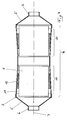
- the exhaust gas purification device shown in Fig. 1 comprises an exhaust gas purification body 1, which means two ring-shaped ones arranged essentially at the ends Bearing elements 2 stored in a housing 3 is.
- the housing includes a tubular bearing section 4 for the exhaust gas purification body 1 and two adjoining the bearing section at the end Transition cones 5. These end in nozzle 6 for Connection of an exhaust pipe.
- the housing 3 is approximately in the middle transverse to the longitudinal axis 7 divided.
- the division level divides the storage section 4 thus in two halves, in an overlap area 8 nested and by means of a fillet weld 9 are connected to each other.
- the central division of the housing allows that each of the two transition cones 5 in one piece with the adjacent half of the bearing section 4 manufactured is and passes into it.
- the tubular bearing section is in his central area is cylindrical.
- the two outer regions 10 of the bearing section 4 taper conically towards the transition cones 5 too, or in other words, they're in Tapering towards the division level educated. Accordingly, the Area of the two conical bearing areas 10 of the between the housing 3 and the exhaust gas purification body 1 each existing annular space 11 in the direction of Division level.
- the exhaust gas purification device shown in Fig. 2 differs essentially by the following features of the exhaust gas purification device 1: Instead of two axially offset
- the exhaust gas cleaning body is an annular bearing element 1 in the housing 3 by means of a storage mat 12 stored, the axial extent of about 50% the axial length of the exhaust gas purification body 1 is. Furthermore, the case is not in the essentially divided in the middle; the division level lies rather in the area of transition one of the two Transition cones 5 to the bearing section 4.
- Overlapped here one molded onto the corresponding transition cone cylindrical collar 13 is also cylindrical End area 14, in which the conical bearing area 10 of the bearing section 4 of the housing runs out.
- the two parts are by means of a fillet weld 9 of the housing firmly connected.
- the storage mat 12 can, for compensation Tolerance-related deviations in the dimensions of the Emission control body 1 of the nominal size in which the Annular space that widens conically towards the division level 11 different positions (see double arrow B).
- the exhaust gas purification device shown in Fig. 3 differs from that according to FIG. 2 in essentially solely because the exhaust gas purification body 1 not by means of a single storage mat is stored in the housing, but rather by means of two axially spaced annular bearing elements 2.
- the bearing section of the housing has two axially spaced conical bearing areas on, between which the housing is cylindrical. According to the different radial width of the two conically widening annular spaces 11 'and 11 ′′ have the two corresponding annular ones Bearing elements 2 'and 2' 'before assembly different radial extension. To this Way is an approximation of the two ring-shaped Bearing elements on the emission control body transferred holding forces to each other possible.
- Annulus can be filled with insulation as is known as such.
- Fig. 4 illustrates another way, a Exhaust gas purification device comprising two exhaust gas cleaning bodies according to the present invention build up.
- 1 to 3 are extensive Comments on the structure of this exhaust gas purification device dispensable. You can see the case assembled from three components, namely one in essentially mirror-symmetrical, too tubular conically widening on both sides Bearing section 4 and two ends of this welded-on transition cones 5. Can be seen of course possible, according to FIG. 4 from three parts assemble assembled housing from four parts, by providing a division in the middle.
- Exhaust gas purifiers apply that manufacture can be done in different ways. Either becomes the emission control body to be installed in each case first measured, and at least one bearing element is on the peripheral surface of the exhaust gas purification body depending on its actual size more or less far from a middle position staggered, whereupon the Unit consisting of exhaust gas cleaning body and around this lying around bearing element (lying around Bearing elements) from the division level of the housing forth - essentially steered - in its Bearing section is inserted until the exhaust gas purification body reached its final position Has.
- Another possibility for assembly is in that the exhaust gas purifier body in its final position within the housing , whereupon the at least one Bearing element in the conically tapered annular space between the emission control body and the housing is introduced; through a force controlled Pressing the bearing element takes this in dependence from the actual dimension of the respective exhaust gas cleaning body automatically that position which ensures a predetermined holding force.
- This The method is particularly suitable if the at least one bearing element by multiple Wrapping the emission control body with a compacted cord is produced.
- a combined procedure at which the respective emission control body in the housing is inserted, but not in its final position, but rather first in an assembly position which is opposite the end position towards the division level is offset.
- the bearing element is then force-controlled brought into the annulus and pre-compressed, wherein the bearing element with an initial contact force pressed against the exhaust gas purification body becomes. Finally, exhaust gas purifiers and Storage element together in the housing in the direction shifted towards its conical taper until the emission control body its final position occupies. This gives the bearing element its final preload.
- FIG. 5 schematically illustrates the structure of a Bearing element made of two axially abutting the (schematically indicated) exhaust gas purification body 1 almost completely surrounding strip 15.
- the Bumps 16 of the two strips depending on which from the actual dimension of the exhaust gas cleaning body 1 forms a more or less wide gap offset against each other. A flow around the exhaust gas purification body is excluded in this way.
- Fig. 6 shows an assembly and compression ring, such as he as part of the above Method in which the bearing element from a put several times around the exhaust gas purification body Cord is built up, can be used.
- the assembly and Compression ring 17 has a feed channel 18 for the cord 19 on.
- With the front edge 20 of the Assembly and compression ring 19 is in the Cord introduced in the annulus force-controlled condensed so that they widen to the conically widening adapts clear cross-section of the annulus.
Landscapes
- Engineering & Computer Science (AREA)
- Chemical & Material Sciences (AREA)
- Chemical Kinetics & Catalysis (AREA)
- Combustion & Propulsion (AREA)
- Mechanical Engineering (AREA)
- General Engineering & Computer Science (AREA)
- Health & Medical Sciences (AREA)
- Toxicology (AREA)
- Exhaust Gas After Treatment (AREA)
Abstract
Description
- Fig. 1
- einen Längsschnitt durch eine erste bevorzugte Ausführungsform einer erfindungsgemäßen Abgasreinigungsvorrichtung,
- Fig. 2
- einen Längsschnitt durch eine zweite bevorzugte Ausführungsform einer erfindungsgemäßen Abgasreinigungsvorrichtung,
- Fig. 3
- einen Längsschnitt durch eine dritte bevorzugte Ausführungsform einer erfindungsgemäßen und
- Fig. 4
- einen Längsschnitt durch eine vierte bevorzugte Ausführungsform einer erfindungsgemäßen Abgasreinigungsvorrichtung.
- Fig. 5
- veranschaulicht schematisch einen zweckmäßigen Aufbau eines im Rahmen der Erfindung zur Lagerung des Abgasreinigungskörpers einsetzbaren Lagerelements und
- Fig. 6
- veranschaulicht ebenfalls schematisch einen Montage- und Verdichtungsring, wie er bei der Herstellung einer bevorzugten Ausführungsform der erfindungsgemäßen Abgasreinigungsvorrichtung eingesetzt werden kann.
Claims (12)
- Abgasreinigungsvorrichtung für ein verbrennungsmotorisch angetriebenes Kraftfahrzeug, umfassend ein Gehäuse (3) und mindestens einen darin unter Zwischenschaltung mindestens eines nachgiebigen Lagerelements (2, 2', 2'', 12) gelagerten, im wesentlichen zylindrischen Abgasreinigungskörper (1), wobei das Gehäuse einen rohrförmigen Lagerabschnitt (4) und zwei hieran endseitig angeschlossene Übergangskonen (5) umfaßt und mindestens in einer sich im wesentlichen senkrecht zur Längsachse (7) erstreckenden Ebene geteilt ist,
dadurch gekennzeichnet,
daß der Lagerabschnitt (4) zumindest bereichsweise (10) sich in Richtung auf die Teilungsebene hin konisch erweiternd ausgebildet ist und daß sich der zwischen dem mindestens einen Abgasreinigungskörper (1) und dem Lagerabschnitt (4) des Gehäuses (3) bestehende, zumindest teilweise von dem Lagerelement (2, 2', 2'', 12) ausgefüllte Ringraum (11) zumindest bereichsweise in Richtung auf die Teilungsebene hin erweitert. - Abgasreinigungvorrichtung nach Anspruch 1,
dadurch gekennzeichnet,
daß als Lagerelement eine den Abgasreinigungskörper (1) zumindest nahezu vollständig umgebende Lagerungsmatte (12) vorgesehen ist, die sich über 40 - 60% der axialen Länge des Abgasreinigungskörpers (1) erstreckt. - Abgasreinigungvorrichtung nach Anspruch 1,
dadurch gekennzeichnet,
daß pro Abgasreinigungskörper (1) zwei in axialer Richtung zueinander versetzt angeordnete, den Abgasreinigungskörper umgebende ringförmige Lagerelemente (2', 2'') vorgesehen sind, die vor ihrer Montage eine unterschiedliche radiale Erstreckung aufweisen. - Abgasreinigungvorrichtung nach Anspruch 3,
dadurch gekennzeichnet,
daß der rohrförmige Lagerabschnitt (4) für jeden Abgasreinigungskörper (1) zwei sich gleichsinnig konisch erweiternde Lagerbereiche (10', 10'') aufweist, zwischen denen sich das Gehäuse (3) im wesentlichen zylindrisch erstreckt. - Abgasreinigungvorrichtung nach einem der Ansprüche 1 bis 4,
dadurch gekennzeichnet,
daß eine Teilungsebene durch den Lagerabschnitt (4) des Gehäuses (3) hindurch verläuft. - Abgasreinigungvorrichtung nach Anspruch 5,
dadurch gekennzeichnet,
daß ein Abgasreinigungskörper (1) vorgesehen ist, der sich in beiden durch die Teilungsebene definierten Hälften des Lagerabschnitts (4) abstützt. - Abgasreinigungvorrichtung nach Anspruch 5,
dadurch gekennzeichnet,
daß zwei Abgasreinigungskörper (1) vorgesehen sind, von denen sich jeweils einer in einer der beiden durch die Teilungsebene definierten Hälften des Lagerbschnitts (4) abstützt. - Abgasreinigungvorrichtung nach einem der Ansprüche 1 bis 7,
dadurch gekennzeichnet,
daß zumindest ein Übergangskonus (5) einstückig mit dem benachbarten Bereich des Lagerabschnitts (4) verbunden ist und in diesen übergeht. - Abgasreinigungvorrichtung nach einem der Ansprüche 1 bis 8,
dadurch gekennzeichnet,
daß das mindestens eine Lagerelement aus einer mindestens einfach, bevorzugt mehrfach um den Abgasreinigungskörper (1) herumgelegten Schnur (19) aufgebaut ist. - Abgasreinigungsvorrichtung nach Anspruch 9,
dadurch geklennzeichnet,
daß die Schnur (19) zumindest bereichsweise mit einem Drahtgewebe (21) überzogen ist. - Abgasreinigungvorrichtung nach einem der Ansprüche 1 bis 8,
dadurch gekennzeichnet,
daß das mindestens eine Lagerelement aus mindestens zwei axial aneinander anliegenden, den Abgasreinigungskörper (1) nahezu vollständig umgebenden Streifen (15) aufgebaut ist, deren Stöße (16) zueinander versetzt sind. - Abgasreinigungvorrichtung nach einem der Ansprüche 1 bis 8,
dadurch gekennzeichnet,
daß das mindestens eine Lagerelement aus einem den Abgasreinigungskörper (1) umgebenden Streifen besteht, dessen Stoß gestuft ausgebildet ist.
Applications Claiming Priority (2)
| Application Number | Priority Date | Filing Date | Title |
|---|---|---|---|
| DE19714851 | 1997-04-10 | ||
| DE19714851A DE19714851C1 (de) | 1997-04-10 | 1997-04-10 | Abgasreinigungsvorrichtung |
Publications (3)
| Publication Number | Publication Date |
|---|---|
| EP0870910A2 true EP0870910A2 (de) | 1998-10-14 |
| EP0870910A3 EP0870910A3 (de) | 1999-12-15 |
| EP0870910B1 EP0870910B1 (de) | 2003-06-04 |
Family
ID=7826040
Family Applications (1)
| Application Number | Title | Priority Date | Filing Date |
|---|---|---|---|
| EP98105368A Expired - Lifetime EP0870910B1 (de) | 1997-04-10 | 1998-03-25 | Abgasreinigungsvorrichtung |
Country Status (2)
| Country | Link |
|---|---|
| EP (1) | EP0870910B1 (de) |
| DE (2) | DE19714851C1 (de) |
Cited By (3)
| Publication number | Priority date | Publication date | Assignee | Title |
|---|---|---|---|---|
| LU90692B1 (en) * | 2000-12-11 | 2002-06-12 | Delphi Tech Inc | Housing for catalytic converter |
| EP1118749A3 (de) * | 2000-01-20 | 2004-01-07 | J. Eberspächer GmbH & Co. KG | Abgaskatalysator |
| JP2005188298A (ja) * | 2003-12-24 | 2005-07-14 | Sakamoto Industry Co Ltd | 触媒コンバータ及びその製造方法 |
Families Citing this family (7)
| Publication number | Priority date | Publication date | Assignee | Title |
|---|---|---|---|---|
| DE19753609A1 (de) * | 1997-12-03 | 1999-06-10 | Leistritz Abgastech | Abgaskatalysator, insbesondere für Kraftfahrzeuge und Verfahren zu seiner Herstellung |
| DE19959241C1 (de) | 1999-12-08 | 2001-04-26 | Zeuna Staerker Kg | Abgasreinigungsvorrichtung |
| DE60118421T2 (de) * | 2000-11-10 | 2006-08-17 | Ibiden Co., Ltd. | Abgaskatalysator, Verfahren zu seiner Herstellung und Halte-und Dichtungsmaterial für Katalysatoren |
| JP4652553B2 (ja) | 2000-11-10 | 2011-03-16 | イビデン株式会社 | 触媒コンバータ及びその製造方法 |
| DE10205856B4 (de) * | 2002-02-13 | 2005-07-07 | J. Eberspächer GmbH & Co. KG | Lagerung eines Keramikmonolithen in einem Blechgehäuse z. B. bei Katalysatoren oder Partikelfiltern |
| DE102008047752B4 (de) * | 2008-09-17 | 2014-10-23 | Tenneco Gmbh | Lagerelement zum Lagern eines Abgaselements, Lagersystem bestehend aus mehreren Lagerelementen sowie Abgassystem bestehend aus Lagersystem und Abgaselement |
| DE102011113539B4 (de) * | 2011-09-15 | 2015-10-01 | Bayern-Chemie Gesellschaft Für Flugchemische Antriebe Mbh | Thermalisolation für Raketentriebwerke |
Citations (2)
| Publication number | Priority date | Publication date | Assignee | Title |
|---|---|---|---|---|
| JPH01280614A (ja) | 1988-04-30 | 1989-11-10 | Suzuki Motor Co Ltd | 触媒保持装置 |
| DE4322062C2 (de) | 1993-07-02 | 1995-10-12 | Schaefer Maschbau Wilhelm | Verfahren zum Herstellen eines Katalysators |
Family Cites Families (9)
| Publication number | Priority date | Publication date | Assignee | Title |
|---|---|---|---|---|
| FR2182614B1 (de) * | 1972-03-17 | 1978-05-05 | Louyot Comptoir Lyon Alemand | |
| DE2331434A1 (de) * | 1973-06-20 | 1975-01-16 | Degussa | Abgasreinigungsvorrichtung |
| GB1602991A (en) * | 1978-05-20 | 1981-11-18 | British Leyland Cars Ltd | Catalytic converters for internal combustion engines |
| JPS57168015A (en) * | 1981-04-10 | 1982-10-16 | Nissan Motor Co Ltd | Holding device of monolis catalyzer for purification of exhaust gas |
| DE3518756A1 (de) * | 1985-05-24 | 1986-11-27 | Audi AG, 8070 Ingolstadt | Abgasleitung einer brennkraftmaschine |
| DE3719773A1 (de) * | 1987-06-13 | 1988-12-22 | Sueddeutsche Kuehler Behr | Traegerkoerper fuer einen katalytischen reaktor |
| JP2640571B2 (ja) * | 1992-04-03 | 1997-08-13 | エミテク・ゲゼルシャフト・フュール・エミシオーンテクノロギー・ミット・ベシュレンクテル・ハフツング | 円錐形のハニカム状の本体 |
| EP0681095B1 (de) * | 1994-05-02 | 1997-11-05 | LEISTRITZ AG & CO. Abgastechnik | Verfahren und Vorrichtung zur Montage eines Abgaskatalysators |
| DE4433974C1 (de) * | 1994-09-23 | 1996-03-28 | Eberspaecher J | Verfahren zur Herstellung von Katalysatoren |
-
1997
- 1997-04-10 DE DE19714851A patent/DE19714851C1/de not_active Expired - Fee Related
-
1998
- 1998-03-25 DE DE59808572T patent/DE59808572D1/de not_active Expired - Fee Related
- 1998-03-25 EP EP98105368A patent/EP0870910B1/de not_active Expired - Lifetime
Patent Citations (2)
| Publication number | Priority date | Publication date | Assignee | Title |
|---|---|---|---|---|
| JPH01280614A (ja) | 1988-04-30 | 1989-11-10 | Suzuki Motor Co Ltd | 触媒保持装置 |
| DE4322062C2 (de) | 1993-07-02 | 1995-10-12 | Schaefer Maschbau Wilhelm | Verfahren zum Herstellen eines Katalysators |
Cited By (4)
| Publication number | Priority date | Publication date | Assignee | Title |
|---|---|---|---|---|
| EP1118749A3 (de) * | 2000-01-20 | 2004-01-07 | J. Eberspächer GmbH & Co. KG | Abgaskatalysator |
| LU90692B1 (en) * | 2000-12-11 | 2002-06-12 | Delphi Tech Inc | Housing for catalytic converter |
| EP1213453A1 (de) * | 2000-12-11 | 2002-06-12 | Delphi Technologies, Inc. | Gehäuse für katalytischen Umwandler |
| JP2005188298A (ja) * | 2003-12-24 | 2005-07-14 | Sakamoto Industry Co Ltd | 触媒コンバータ及びその製造方法 |
Also Published As
| Publication number | Publication date |
|---|---|
| EP0870910A3 (de) | 1999-12-15 |
| EP0870910B1 (de) | 2003-06-04 |
| DE59808572D1 (de) | 2003-07-10 |
| DE19714851C1 (de) | 1998-10-01 |
Similar Documents
| Publication | Publication Date | Title |
|---|---|---|
| DE19711789C2 (de) | Kraftfahrzeug-Abgasreinigungsvorrichtung und Verfahren zu ihrer Herstellung | |
| EP0618096B1 (de) | Gummilager für den Mittelzapfen einer Blattfederaufhängung in einem Kraftfahrzeug | |
| DE4317334C1 (de) | Vorrichtung zum flexiblen Verbinden von Rohren in Abgasleitungen von Kraftfahrzeugen | |
| EP2282825B1 (de) | Filtersystem | |
| EP0552706A1 (de) | Filtervorrichtung zum Filtern einer Gasströmung | |
| DE2636956A1 (de) | Schalldaempfer | |
| DE19780763B3 (de) | Gasgenerator für einen Airbag | |
| EP1092461A1 (de) | Filterpatrone mit Mittelrohr | |
| EP0870910B1 (de) | Abgasreinigungsvorrichtung | |
| EP0471175B1 (de) | Verfahren zur Herstellung einer Vorrichtung zur katalytischen Reinigung bzw. Zerlegung von heissen Abgasen | |
| WO1999015803A1 (de) | Elastischer gelenkkörper | |
| DE7800585U1 (de) | Staubsaugerschlauch | |
| DE10300780A1 (de) | Abgasbehandlungseinrichtung | |
| EP0405245B1 (de) | Schlauchanschlussarmatur für einen Hochdruckschlauch | |
| EP0747582A2 (de) | Entkopplungselement für Schwingungen in Rohrleitungen | |
| EP3413414B1 (de) | Dichtungsmuffe für einen rohrverband | |
| EP0709558B1 (de) | Leitungselement, insbesondere für die Abgasleitung von Verbrennungskraftmaschinen | |
| DE4004072A1 (de) | Doppelwandhohlkoerper mit zwischenlage und verfahren zur herstellung desselben | |
| EP0872005B1 (de) | Lamelle für elektrodynamische maschinen | |
| DE2637726C3 (de) | Streckenausbaurahmen | |
| DE102004056804B4 (de) | Katalysator und/oder Partikelfilter sowie zugehöriges Herstellungsverfahren und zugehörige Lagermatte | |
| DE4317333C2 (de) | Vorrichtung zum Dämpfen von Schwingungen in Abgasleitungen von Kraftfahrzeugen | |
| DE4244315A1 (de) | Katalytische Abgasreinigungsvorrichtung | |
| DE102007018915A1 (de) | Stützwendel mit mechanischer Verriegelung und Verfahren zu deren Herstellung | |
| EP3770396B1 (de) | Abgasnachbehandlungsvorrichtung für eine abgasanlage eines kraftfahrzeugs sowie kraftfahrzeug mit einer derartigen abgasnachbehandlungsvorrichtung |
Legal Events
| Date | Code | Title | Description |
|---|---|---|---|
| PUAI | Public reference made under article 153(3) epc to a published international application that has entered the european phase |
Free format text: ORIGINAL CODE: 0009012 |
|
| AK | Designated contracting states |
Kind code of ref document: A2 Designated state(s): DE FR IT |
|
| AX | Request for extension of the european patent |
Free format text: AL;LT;LV;MK;RO;SI |
|
| PUAL | Search report despatched |
Free format text: ORIGINAL CODE: 0009013 |
|
| AK | Designated contracting states |
Kind code of ref document: A3 Designated state(s): AT BE CH DE DK ES FI FR GB GR IE IT LI LU MC NL PT SE |
|
| AX | Request for extension of the european patent |
Free format text: AL;LT;LV;MK;RO;SI |
|
| 17P | Request for examination filed |
Effective date: 20000127 |
|
| AKX | Designation fees paid |
Free format text: DE FR IT |
|
| 17Q | First examination report despatched |
Effective date: 20010221 |
|
| GRAG | Despatch of communication of intention to grant |
Free format text: ORIGINAL CODE: EPIDOS AGRA |
|
| RAP1 | Party data changed (applicant data changed or rights of an application transferred) |
Owner name: ZEUNA-STAERKER GMBH & CO KG |
|
| GRAG | Despatch of communication of intention to grant |
Free format text: ORIGINAL CODE: EPIDOS AGRA |
|
| GRAH | Despatch of communication of intention to grant a patent |
Free format text: ORIGINAL CODE: EPIDOS IGRA |
|
| GRAH | Despatch of communication of intention to grant a patent |
Free format text: ORIGINAL CODE: EPIDOS IGRA |
|
| GRAA | (expected) grant |
Free format text: ORIGINAL CODE: 0009210 |
|
| AK | Designated contracting states |
Designated state(s): DE FR IT |
|
| PG25 | Lapsed in a contracting state [announced via postgrant information from national office to epo] |
Ref country code: IT Free format text: LAPSE BECAUSE OF FAILURE TO SUBMIT A TRANSLATION OF THE DESCRIPTION OR TO PAY THE FEE WITHIN THE PRE;WARNING: LAPSES OF ITALIAN PATENTS WITH EFFECTIVE DATE BEFORE 2007 MAY HAVE OCCURRED AT ANY TIME BEFORE 2007. THE CORRECT EFFECTIVE DATE MAY BE DIFFERENT FROM THE ONE RECORDED.SCRIBED TIME-LIMIT Effective date: 20030604 Ref country code: FR Free format text: LAPSE BECAUSE OF FAILURE TO SUBMIT A TRANSLATION OF THE DESCRIPTION OR TO PAY THE FEE WITHIN THE PRESCRIBED TIME-LIMIT Effective date: 20030604 |
|
| REF | Corresponds to: |
Ref document number: 59808572 Country of ref document: DE Date of ref document: 20030710 Kind code of ref document: P |
|
| PLBE | No opposition filed within time limit |
Free format text: ORIGINAL CODE: 0009261 |
|
| STAA | Information on the status of an ep patent application or granted ep patent |
Free format text: STATUS: NO OPPOSITION FILED WITHIN TIME LIMIT |
|
| 26N | No opposition filed |
Effective date: 20040305 |
|
| EN | Fr: translation not filed | ||
| PGFP | Annual fee paid to national office [announced via postgrant information from national office to epo] |
Ref country code: DE Payment date: 20050512 Year of fee payment: 8 |
|
| PG25 | Lapsed in a contracting state [announced via postgrant information from national office to epo] |
Ref country code: DE Free format text: LAPSE BECAUSE OF NON-PAYMENT OF DUE FEES Effective date: 20061003 |