EP0871030A2 - Capteur électrochimique - Google Patents
Capteur électrochimique Download PDFInfo
- Publication number
- EP0871030A2 EP0871030A2 EP98201667A EP98201667A EP0871030A2 EP 0871030 A2 EP0871030 A2 EP 0871030A2 EP 98201667 A EP98201667 A EP 98201667A EP 98201667 A EP98201667 A EP 98201667A EP 0871030 A2 EP0871030 A2 EP 0871030A2
- Authority
- EP
- European Patent Office
- Prior art keywords
- plugs
- sensor
- plug
- electrode
- electrolyte
- Prior art date
- Legal status (The legal status is an assumption and is not a legal conclusion. Google has not performed a legal analysis and makes no representation as to the accuracy of the status listed.)
- Ceased
Links
- 230000004888 barrier function Effects 0.000 claims abstract 2
- 239000003792 electrolyte Substances 0.000 claims description 21
- 239000000463 material Substances 0.000 claims description 10
- 229920006395 saturated elastomer Polymers 0.000 claims description 5
- 239000011521 glass Substances 0.000 abstract description 32
- 238000005470 impregnation Methods 0.000 abstract description 4
- 239000007787 solid Substances 0.000 abstract description 3
- 239000012530 fluid Substances 0.000 description 34
- 239000002023 wood Substances 0.000 description 19
- 150000002500 ions Chemical class 0.000 description 12
- 239000000565 sealant Substances 0.000 description 12
- 239000007788 liquid Substances 0.000 description 11
- 238000000034 method Methods 0.000 description 9
- 230000008569 process Effects 0.000 description 8
- 239000000243 solution Substances 0.000 description 8
- 230000008961 swelling Effects 0.000 description 7
- 239000004593 Epoxy Substances 0.000 description 6
- 238000007789 sealing Methods 0.000 description 6
- 238000012360 testing method Methods 0.000 description 6
- 238000013461 design Methods 0.000 description 5
- 239000011148 porous material Substances 0.000 description 5
- 150000003568 thioethers Chemical class 0.000 description 5
- 238000012546 transfer Methods 0.000 description 5
- 238000006243 chemical reaction Methods 0.000 description 4
- 229910021645 metal ion Inorganic materials 0.000 description 4
- 239000000919 ceramic Substances 0.000 description 3
- 238000012544 monitoring process Methods 0.000 description 3
- 239000012266 salt solution Substances 0.000 description 3
- 150000003839 salts Chemical class 0.000 description 3
- 238000010186 staining Methods 0.000 description 3
- 239000000126 substance Substances 0.000 description 3
- UCKMPCXJQFINFW-UHFFFAOYSA-N Sulphide Chemical group [S-2] UCKMPCXJQFINFW-UHFFFAOYSA-N 0.000 description 2
- -1 TeflonTM Substances 0.000 description 2
- 239000000853 adhesive Substances 0.000 description 2
- 230000001070 adhesive effect Effects 0.000 description 2
- 230000000295 complement effect Effects 0.000 description 2
- 230000008878 coupling Effects 0.000 description 2
- 238000010168 coupling process Methods 0.000 description 2
- 238000005859 coupling reaction Methods 0.000 description 2
- 230000000694 effects Effects 0.000 description 2
- 239000003822 epoxy resin Substances 0.000 description 2
- 238000005259 measurement Methods 0.000 description 2
- 229910052751 metal Inorganic materials 0.000 description 2
- 239000002184 metal Substances 0.000 description 2
- 238000002156 mixing Methods 0.000 description 2
- 229920000647 polyepoxide Polymers 0.000 description 2
- 238000004382 potting Methods 0.000 description 2
- 230000036647 reaction Effects 0.000 description 2
- UGFAIRIUMAVXCW-UHFFFAOYSA-N Carbon monoxide Chemical compound [O+]#[C-] UGFAIRIUMAVXCW-UHFFFAOYSA-N 0.000 description 1
- 229920002449 FKM Polymers 0.000 description 1
- KRHYYFGTRYWZRS-UHFFFAOYSA-M Fluoride anion Chemical compound [F-] KRHYYFGTRYWZRS-UHFFFAOYSA-M 0.000 description 1
- 229910021607 Silver chloride Inorganic materials 0.000 description 1
- RTAQQCXQSZGOHL-UHFFFAOYSA-N Titanium Chemical compound [Ti] RTAQQCXQSZGOHL-UHFFFAOYSA-N 0.000 description 1
- 238000010521 absorption reaction Methods 0.000 description 1
- 238000007792 addition Methods 0.000 description 1
- 230000008901 benefit Effects 0.000 description 1
- 229940075397 calomel Drugs 0.000 description 1
- GTKRFUAGOKINCA-UHFFFAOYSA-M chlorosilver;silver Chemical compound [Ag].[Ag]Cl GTKRFUAGOKINCA-UHFFFAOYSA-M 0.000 description 1
- 238000004891 communication Methods 0.000 description 1
- 230000001010 compromised effect Effects 0.000 description 1
- 239000004020 conductor Substances 0.000 description 1
- 238000010276 construction Methods 0.000 description 1
- 238000002425 crystallisation Methods 0.000 description 1
- 230000008025 crystallization Effects 0.000 description 1
- 230000007423 decrease Effects 0.000 description 1
- 230000032798 delamination Effects 0.000 description 1
- 238000012217 deletion Methods 0.000 description 1
- 230000037430 deletion Effects 0.000 description 1
- ZOMNIUBKTOKEHS-UHFFFAOYSA-L dimercury dichloride Chemical compound Cl[Hg][Hg]Cl ZOMNIUBKTOKEHS-UHFFFAOYSA-L 0.000 description 1
- 229920001971 elastomer Polymers 0.000 description 1
- 239000012467 final product Substances 0.000 description 1
- 239000003546 flue gas Substances 0.000 description 1
- 210000004907 gland Anatomy 0.000 description 1
- 239000005337 ground glass Substances 0.000 description 1
- 238000003780 insertion Methods 0.000 description 1
- 230000037431 insertion Effects 0.000 description 1
- 230000002427 irreversible effect Effects 0.000 description 1
- 238000012986 modification Methods 0.000 description 1
- 230000004048 modification Effects 0.000 description 1
- 230000035515 penetration Effects 0.000 description 1
- 239000004033 plastic Substances 0.000 description 1
- 239000002574 poison Substances 0.000 description 1
- 231100000614 poison Toxicity 0.000 description 1
- 231100000572 poisoning Toxicity 0.000 description 1
- 230000000607 poisoning effect Effects 0.000 description 1
- 239000002244 precipitate Substances 0.000 description 1
- 229910052709 silver Inorganic materials 0.000 description 1
- 239000004332 silver Substances 0.000 description 1
- HKZLPVFGJNLROG-UHFFFAOYSA-M silver monochloride Chemical compound [Cl-].[Ag+] HKZLPVFGJNLROG-UHFFFAOYSA-M 0.000 description 1
- 229910001220 stainless steel Inorganic materials 0.000 description 1
- 239000010935 stainless steel Substances 0.000 description 1
- 239000010936 titanium Substances 0.000 description 1
- 229910052719 titanium Inorganic materials 0.000 description 1
- 238000004065 wastewater treatment Methods 0.000 description 1
Images
Classifications
-
- G—PHYSICS
- G01—MEASURING; TESTING
- G01N—INVESTIGATING OR ANALYSING MATERIALS BY DETERMINING THEIR CHEMICAL OR PHYSICAL PROPERTIES
- G01N27/00—Investigating or analysing materials by the use of electric, electrochemical, or magnetic means
- G01N27/02—Investigating or analysing materials by the use of electric, electrochemical, or magnetic means by investigating impedance
- G01N27/04—Investigating or analysing materials by the use of electric, electrochemical, or magnetic means by investigating impedance by investigating resistance
- G01N27/06—Investigating or analysing materials by the use of electric, electrochemical, or magnetic means by investigating impedance by investigating resistance of a liquid
-
- G—PHYSICS
- G01—MEASURING; TESTING
- G01N—INVESTIGATING OR ANALYSING MATERIALS BY DETERMINING THEIR CHEMICAL OR PHYSICAL PROPERTIES
- G01N27/00—Investigating or analysing materials by the use of electric, electrochemical, or magnetic means
- G01N27/26—Investigating or analysing materials by the use of electric, electrochemical, or magnetic means by investigating electrochemical variables; by using electrolysis or electrophoresis
- G01N27/28—Electrolytic cell components
- G01N27/401—Salt-bridge leaks; Liquid junctions
Definitions
- This invention relates to instruments for sensing the characteristics of a fluid, more particularly to electrochemical sensors and particularly, but not exclusively, to reference cells used in pH, ORP, or other specific ion sensors.
- the reference cell used in pH, ORP, or other specific ion sensors typically utilizes a metal-metal salt (e.g., Ag/AgCl) element.
- a metal-metal salt e.g., Ag/AgCl
- a suitable electrolyte in the form of a salt solution must link this element to the specimen fluid.
- This electrolyte provides the conductive, i.e., salt, bridge to the specimen fluid and surrounds the reference element with an electrochemically stable environment.
- the region where the electrolyte meets the specimen fluid is called the liquid junction and usually takes the form of a porous material.
- the ideal liquid junction would provide electrolytic contact between the reference element and specimen fluid while preventing any mixing of the specimen fluid with this electrolyte. In practice, mixing is usually unavoidable and can cause undesirable effects. Thus, the liquid junction is typically the weakest point of a reference cell design.
- a common problem with liquid junctions is maintaining a conductive path between the specimen fluid and the reference element. Liquid junctions with small openings can easily be plugged by solids contained within the specimen fluid or by crystallization of the specimen fluid with the electrolyte through some type of chemical reaction. To reduce plugging problems, large junction surfaces have been employed.
- Each of the large plugs has a pair of side apertures which are axially displaced on opposite sides of the plug's central bore.
- the side apertures are used to receive the smaller plugs which are inserted midway into one of the side apertures in successive pairs of the large plugs on opposite sides of the central bore.
- the ' 333 Patent teaches that the sealant fills the intervening spaces within the side apertures to seal off the fluid path between successive smaller plugs on each side. Therefore, the ' 333 Patent teaches that the combination of large and small plugs and sealant provides a circuitous path for ion transfer.
- the entire structure is immersed in a bath containing the reference cell electrolyte or salt bridge solution until the wood is thoroughly impregnated with this solution throughout the entire length of the container.
- the ' 333 Patent teaches that the absorption of the salt bridge solution into the reference cell structure causes swelling of the large and small wood plugs. This swelling causes the wood to expand in the transverse direction which causes the plugs to tightly press against one another, the central glass electrode and the inside of the rigid cylindrical container used to house the cell. While not expressly stated in the ' 333 Patent, this swelling of the wood would lead one skilled in the art to presume that there would be very little if any ion transfer in that part of each plug adjacent to the glass electrode and cylindrical container.
- epoxy has also been used to seal the outside surface of each of the large plugs. It was believed that using the epoxy on the outside surface would further ensure that there would not be any ion transfer along a path through the outside surface of each plug.
- Reference cells constructed in accordance with the teachings of the ' 333 Patent have been and continue to be used successfully in the continuous monitoring of process streams.
- One such application is in the monitoring of process streams wherein sulfides are present.
- Such streams may occur in petrochemical processes, flue gas scrubbers, and waste water treatment.
- the presence of sulfides in these streams has been shown to shorten the life of a reference cell.
- As sulfides penetrate into the reference cell structure and come in contact with the metal ions involved in the reference cell reaction e.g., silver
- an insoluble sulfide salt forms and precipitates out of solution.
- Such loading may cause breakage of the glass electrode when a sensor that uses porous material in its liquid junction design is placed into service in process streams having elevated temperatures, pressures and/or containing harsh chemicals.
- sensors are those shown in the '333 Patent and also in U.S. Patent No. 5,147,524 (“the ' 524 Patent”) and U.S. Patent No. 5,346,606 (“the ' 606 Patent”).
- the heat, pressure and/or chemicals may cause the porous material to expand and fracture the glass electrode. Therefore, it is desirable to strengthen the sensor to thereby eliminate this cause of glass electrode fracture and thus allow a sensing device to be provided having a consistent quality and performance.
- the present invention is embodied in a device for use in connection with measuring ionic properties in a specimen fluid.
- the device has a salt bridge which is made up of a first longitudinal series of semipermeable plugs impregnated with an electrolyte; and a second longitudinal series of semipermeable plugs impregnated with an electrolyte.
- the first and said second series of semipermeable plugs are disposed in a longitudinally overlapping relationship with an interlocking fit.
- the device also has a series of impermeable plugs.
- Each of the impermeable plugs are associated with a pair of adjoining transverse end surfaces of the first series of plugs and are interposed therebetween.
- a plug in the second series of plugs passes through each of the impermeable plugs to thereby provide an ion path between the adjoining transverse end surfaces.
- the present invention is also embodied as a device for use in connection with measuring ionic properties in a specimen fluid that has a salt bridge wherein the first longitudinal series of semipermeable plugs has at least two plugs and the second longitudinal series of semipermeable plugs has at least one plug.
- the first and second series of plugs are disposed in a longitudinally overlapping relationship with an interlocking fit.
- the device also includes a series of impermeable plugs having at least one plug associated with adjoining transverse end surfaces of the at least two plugs in the first series and is interposed therebetween.
- the at least one plug in the second series passes through the at least one impermeable plug to thereby provide an ion path between the adjoining transverse end surfaces.
- the present invention is further embodied as a device for use in connection with measuring ionic properties in a specimen fluid that has a salt bridge.
- the salt bridge has first and second longitudinal semipermeable plugs impregnated with an electrolyte; and a third longitudinal semipermeable plug impregnated with an electrolyte.
- the first, second and third plugs are disposed in a longitudinally overlapping relationship with an interlocking fit.
- the device further has an impermeable plug interposed between adjoining transverse end surfaces of the first and second semipermeable plugs.
- the third semipermeable plug passes through the impermeable plug to thereby provide an ion path between the adjoining transverse end surfaces.
- the present invention is also embodied as an electrochemical sensor.
- the sensor has a reference electrode; a sensing electrode; a rigid liner; and a salt bridge.
- the salt bridge has a plug made of semipermeable material saturated with an electrolyte.
- the plug has a central axial bore for holding the rigid liner therein.
- the rigid liner has a central axial bore for holding the sensing electrode therein.
- the present invention is also further embodied as an electrochemical sensor.
- the sensor has a semipermeable plug impregnated with an electrolyte.
- the plug has a central bore and axially separated first and second ends and functions as a salt bridge.
- the sensor further has a rigid liner in the axial bore; a sensing electrode positioned at the first end and adapted to contact a specimen fluid; and a reference electrode positioned at the second end.
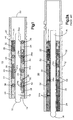
- Fig. 1 shows a cross sectional view of a sensor embodied in accordance with one aspect of the present invention.
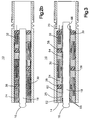
- Fig. 2a shows a cross sectional view of a sensor constructed in accordance with the teachings of the ' 333 Patent at the end of the ink test.
- Fig. 2b shows a cross sectional view of the sensor shown in Fig. 1 at the end of the ink test.
- Fig. 3 shows a cross sectional view of the sensor of Fig. 1 including a rigid liner in accordance with another aspect of the present invention.
- Fig. 1 there is shown a cross sectional view of a sensor 10 embodied in accordance with the life expectancy increasing features of the present invention.
- the sensor may be used for measuring pH, ORP or specific ions in a specimen fluid (not shown).
- the senor 10 includes a housing 12 which is preferably cylindrically shaped.
- housing 12 is formed with high density polyvinyldiene fluoride plastic or other material that has the desired structural rigidity and is inert or otherwise chemically compatible with the specimen fluid.
- the housing 12 has a first end 14, and the bulb 16 of a conventional glass sensing electrode 18 protrudes from the first end 14 to contact the specimen fluid for measuring, for example, the pH of the specimen fluid.
- Fig. 1 also shows that the housing 12 has a second end 20, and that a coupling sleeve (not shown) and the O-ring glands 22, can be used to seal the second end 20 from the specimen sample, and that this coupling sleeve provides for the necessary engagement with a complementary fitting (not shown) on a pipe, tank, or other vessel that holds the specimen fluid.
- electrical leads (not shown) are attached to the glass sensing electrode 18 and reference electrode 32 and extend outwardly from the second end 20.
- the electrical leads are for attachment to a suitable device, for example, a pH meter, which can process the signal generated by the sensor 10 and indicate the pH of the specimen fluid.
- the second end 20 is fill with a potting material (not shown) suitable for the type of environments typical for this device. The potting establishes a seal between the electrical leads, rear of button 38 and housing 12.
- the first series consists of four thick walled hollow cylindrical or annular shaped larger plugs 24 that fit snugly within the housing 12.
- Each of the plugs 24 have a central bore 26 that slidably receives the axially disposed glass electrode 18 at the center of the housing.
- Each of the adjoining surfaces 24a of plugs 24 also has a single longitudinally extending side aperture 28 axially displaced on one side of the central bore 26. The aperture 28 only extends about halfway through each plug.
- the second series of plugs are the three solid cylinders 30 that are slidably insertable into the side apertures 28 of adjacent pairs of the plugs 24.
- the plugs 30 have approximately the same longitudinal dimensions as the plugs 24 for insertion midway into the side apertures 28 thus overlapping the longitudinal extent of adjacent pairs of plugs 24. Only one plug 30 is used between each adjacent pair of plugs 24 with successive ones on alternate sides of the central bore 26.
- the sensor includes a reference electrode or element 32 that has an electrical lead 34 which accompanies the electrical lead of the sensing glass electrode 18.
- the plug 24 closest to second end 20 may include a cavity 36 for receiving the reference element 32.
- the reference electrode 32 is typically a conventional silver-silver chloride or calomel type electrode.
- the plugs 24 and 30 are saturated, that is, impregnated, with an appropriate electrolyte such as a saturated salt solution. This saturation allows electrical communication to be established through the plugs 24 and 30 between the reference electrode 32 and the specimen fluid in which the bulb 16 of the measurement electrode 18 is immersed.
- each of the larger plugs has a pair of longitudinally extending side apertures completely therethrough while the sensor described herein has the longitudinally extending apertures 28 only partway through the plug 24.
- the ' 333 Patent describes and shows a set of cylindrical plugs which are about twice as long as the plugs 30 described herein.
- the ' 333 Patent teaches that an epoxy resin or other adhesive sealant should be used to seal the abutting end surfaces of the plugs 24 prior to assembly of the sensor.
- the ' 333 Patent teaches that the sealant fills the intervening spaces within the side apertures 28 to seal off the fluid path between successive smaller plugs 30 on each side of the larger plugs 24.
- epoxy has also been used to seal the outside surface of each of the large plugs 24.
- buttons 38, 39 include a pair of semicircular protrusions 40 by which an O-ring type seal is provided against the housing 12. All of the buttons 38, 39 have a central bore 38a, 39a for slidably receiving the glass electrode 18. These central bores have a pair of semicircular protrusions 40a similar to protrusions 40 to thereby provide an O-ring type seal with the glass electrode 18.
- buttons 38 which separate the adjacent end surfaces of the plugs 24 each further include a single longitudinally extending side channel 42 completely therethrough for receiving the associated plug 30.
- the side channel 42 provides limited clearance of the associated plug 30 so that the squeeze created from the semicircular protrusions 40 and 40a causes channel 42 to tightly squeeze against the associated plug 30.
- the button 39 which seals the second end 20 does not include channel 42 but does include a single longitudinally extending side channel 44 completely therethrough for receiving the electrical lead 34 of the reference electrode 32.
- the impermeable material used to fabricate the buttons 38, 39 is VITON® rubber which is available from E. I. Du Pont De Neumors & Co.
- a sensor embodied as shown in Fig. 1 would have a longer life than a sensor constructed in accordance with the teaching of the '333 Patent
- the two sensors were tested at the same time and identically.
- sensor life can be inferred by comparing the penetration of the ink solution into each sensor over a period of a few days.
- both sensors including wooden plugs were longitudinally cut open.
- Fig. 2a a cross sectional view of a sensor 50 constructed in accordance with the teachings of the '333 Patent at the end of the ink test and in Fig. 2b a cross sectional view of the sensor 10 shown in Fig. 1 also at the end of the ink test.
- the results of the ink test for both sensors is shown in Figs. 2a and 2b by the dark shading, which represents the ink stains, on the plugs 24 and 30.
- the ink stains in sensor 10 showed a uniformed progression leading from the specimen fluid contact point through each of the large and small plugs 24 and 30. Staining showed complete saturation of each large plug 24 before any appreciable staining was observed in the next adjacent large plug 24.
- the ink stains in the sensor 10 of the present invention and the sensor 50 of the ' 333 Patent prove that if the ' 333 Patent sensor or its modified form (i.e., with elastomeric sealant) had been used in a sulfide application its reference cell would have been poisoned much sooner than the reference cell of the sensor 10.
- FIG. 3 there is shown a cross sectional view of a further embodiment of sensor 10 which includes a rigid tubular liner 60 around the glass electrode 18.
- the wall 64 of the rigid liner 60 is thicker in portion 62 adjacent to first end 14 then elsewhere.
- the increased wall thickness in portion 62 allows for the use of standard size O-rings 66 which provides a seal to prevent the specimen fluid from reaching the potted electrical leads and aid in retaining the glass electrode 18.
- Each of the large plugs 24 must be reduced slightly in diameter as compared to their diameter in the sensor shown in Fig. 1 in order to accommodate liner 60.
- the portion of the plug 24 which is closest to end 14 must have a step 25 therein which is complementary to portion 62.
- the rigid liner 60 has a groove 68 which is used to accommodate a snap ring 70.
- the snap ring 70 retains the assembly made up of plugs 24, 30, buttons 38, 39, liner 60 and O-rings 66. This allows the glass electrode 18 to be inserted into that assembly just prior to shipment of the sensor 10.
- the rigid liner 60 was constructed from either stainless steel or titanium.
- the rigid liner may, however, be constructed from any material that can withstand the shear stresses that may result when the sensor is impregnated and later placed into service in process streams having elevated temperatures, pressures and/or containing harsh chemicals.
- An advantage of using an electrically conductive material for the liner is in those applications which require a solution ground. In such applications the ground can easily be provided by connecting a wire (not shown) to the snap ring 70.
- Liner 60 has been shown in Fig. 3 in combination with sensor 10 of Fig. 1. It should, however, be appreciated that the liner may also be used with sensor 50 of Fig. 2a or any other type of sensor which uses a porous material in its liquid junction and has an electrode that may fracture under shear stresses.
Landscapes
- Chemical & Material Sciences (AREA)
- Life Sciences & Earth Sciences (AREA)
- Health & Medical Sciences (AREA)
- Biochemistry (AREA)
- Chemical Kinetics & Catalysis (AREA)
- Electrochemistry (AREA)
- Physics & Mathematics (AREA)
- Analytical Chemistry (AREA)
- General Health & Medical Sciences (AREA)
- General Physics & Mathematics (AREA)
- Immunology (AREA)
- Pathology (AREA)
- Molecular Biology (AREA)
- Investigating Or Analyzing Materials By The Use Of Electric Means (AREA)
- Measuring Oxygen Concentration In Cells (AREA)
- Measurement Of The Respiration, Hearing Ability, Form, And Blood Characteristics Of Living Organisms (AREA)
Applications Claiming Priority (3)
| Application Number | Priority Date | Filing Date | Title |
|---|---|---|---|
| US569035 | 1995-12-07 | ||
| US08/569,035 US5630921A (en) | 1995-12-07 | 1995-12-07 | Electrochemical sensor |
| EP96119287A EP0777122B1 (fr) | 1995-12-07 | 1996-12-02 | Capteur électrochimique |
Related Parent Applications (1)
| Application Number | Title | Priority Date | Filing Date |
|---|---|---|---|
| EP96119287A Division EP0777122B1 (fr) | 1995-12-07 | 1996-12-02 | Capteur électrochimique |
Publications (2)
| Publication Number | Publication Date |
|---|---|
| EP0871030A2 true EP0871030A2 (fr) | 1998-10-14 |
| EP0871030A3 EP0871030A3 (fr) | 1998-11-18 |
Family
ID=24273827
Family Applications (2)
| Application Number | Title | Priority Date | Filing Date |
|---|---|---|---|
| EP98201667A Ceased EP0871030A3 (fr) | 1995-12-07 | 1996-12-02 | Capteur électrochimique |
| EP96119287A Expired - Lifetime EP0777122B1 (fr) | 1995-12-07 | 1996-12-02 | Capteur électrochimique |
Family Applications After (1)
| Application Number | Title | Priority Date | Filing Date |
|---|---|---|---|
| EP96119287A Expired - Lifetime EP0777122B1 (fr) | 1995-12-07 | 1996-12-02 | Capteur électrochimique |
Country Status (12)
| Country | Link |
|---|---|
| US (1) | US5630921A (fr) |
| EP (2) | EP0871030A3 (fr) |
| JP (1) | JPH09178691A (fr) |
| KR (1) | KR100421741B1 (fr) |
| CN (1) | CN1103050C (fr) |
| AU (1) | AU685031B2 (fr) |
| BR (1) | BR9605383B1 (fr) |
| CA (1) | CA2185879C (fr) |
| DE (1) | DE69620552T2 (fr) |
| ES (1) | ES2181838T3 (fr) |
| NO (1) | NO964392L (fr) |
| SG (1) | SG44980A1 (fr) |
Families Citing this family (17)
| Publication number | Priority date | Publication date | Assignee | Title |
|---|---|---|---|---|
| US5970428A (en) * | 1997-10-08 | 1999-10-19 | Elsag International N.V. | Ground loop detector circuit and method |
| US6416653B1 (en) * | 2000-07-18 | 2002-07-09 | Barben Analyzer Technology, Llc | Device for separating electrolyte chambers within an electrochemical sensor |
| US10022078B2 (en) | 2004-07-13 | 2018-07-17 | Dexcom, Inc. | Analyte sensor |
| US20050040038A1 (en) * | 2003-04-02 | 2005-02-24 | Larry Berger | Diagnostic electro-chemical reference half cell |
| DE10334854A1 (de) * | 2003-07-29 | 2005-03-10 | Endress & Hauser Gmbh & Co Kg | Drucksensor |
| US7920906B2 (en) | 2005-03-10 | 2011-04-05 | Dexcom, Inc. | System and methods for processing analyte sensor data for sensor calibration |
| US9247900B2 (en) | 2004-07-13 | 2016-02-02 | Dexcom, Inc. | Analyte sensor |
| US20050153647A1 (en) * | 2004-01-14 | 2005-07-14 | Thomas Roger O. | Flues for industrial chimneys |
| US8792955B2 (en) | 2004-05-03 | 2014-07-29 | Dexcom, Inc. | Transcutaneous analyte sensor |
| US8565848B2 (en) | 2004-07-13 | 2013-10-22 | Dexcom, Inc. | Transcutaneous analyte sensor |
| US8989833B2 (en) | 2004-07-13 | 2015-03-24 | Dexcom, Inc. | Transcutaneous analyte sensor |
| EP1710567A1 (fr) * | 2005-04-08 | 2006-10-11 | Hach Lange GmbH | Cartouche de capteur pour l'analyse d'eau résiduelle |
| FR2898978B1 (fr) * | 2006-03-23 | 2008-08-29 | Adca Electronique Sa | Cellule de mesure de potentiel pour la surveillance des installations a protection cathodique par soutirage |
| US7867371B2 (en) * | 2006-09-21 | 2011-01-11 | Georg Fischer Signet, LLC | Electrochemical sensor and method of manufacture |
| US7909972B2 (en) * | 2006-11-28 | 2011-03-22 | Georg Fischer Signet Llc | Electrochemical sensor and method of manufacture |
| US7799193B2 (en) * | 2007-03-05 | 2010-09-21 | Georg Fischer Signet Llc | Electrochemical sensor and method of manufacture |
| CN104515794B (zh) * | 2015-01-06 | 2017-10-24 | 上海今见电子科技有限公司 | Ph/orp传感器 |
Family Cites Families (18)
| Publication number | Priority date | Publication date | Assignee | Title |
|---|---|---|---|---|
| US3145157A (en) * | 1961-09-26 | 1964-08-18 | Beckman Instruments Inc | Ion sensitive electrode |
| US3264205A (en) * | 1962-06-25 | 1966-08-02 | Beckman Instruments Inc | Leak structure for electrochemical electrodes |
| US3498899A (en) * | 1965-06-18 | 1970-03-03 | Beckman Instruments Inc | Electrochemical electrode assembly |
| US3440525A (en) * | 1966-04-13 | 1969-04-22 | Universal Interloc Inc | Ph meter and control system |
| CH610665A5 (fr) * | 1976-03-12 | 1979-04-30 | Hoffmann La Roche | |
| DE2706942A1 (de) * | 1976-03-17 | 1977-09-29 | Owens Illinois Inc | Kombinationselektrode |
| USRE31333E (en) * | 1977-10-11 | 1983-08-02 | Electrochemical reference cell with improved liquid junction | |
| US4128468A (en) * | 1978-01-03 | 1978-12-05 | Bukamier Gary L | Electrode structures |
| DK436381A (da) * | 1981-10-01 | 1983-04-02 | Radiometer As | Elektrokemisk elektrodeindretning |
| US4543175A (en) * | 1983-08-08 | 1985-09-24 | Gam Rad, Inc. | Ion responsive probe |
| GB2182446A (en) * | 1985-11-08 | 1987-05-13 | Bert Settler | Antimony electrode assembly |
| US4888102A (en) * | 1988-07-28 | 1989-12-19 | The United States Of America As Represented By The United States Department Of Energy | Electrolytic cell with reference electrode |
| GB2245707A (en) * | 1990-06-23 | 1992-01-08 | Sycopel Scient Ltd | Screened electrochemical electrode |
| US5147524A (en) * | 1991-07-25 | 1992-09-15 | Broadley-James Corporation | pH sensor |
| US5221456A (en) * | 1991-10-22 | 1993-06-22 | Rosemount Inc. | Insulated core electrode for ph sensor |
| EP0609763B1 (fr) * | 1993-02-04 | 1998-07-08 | Hoechst Aktiengesellschaft | Electrode à PH en verre |
| US5346606A (en) * | 1993-08-16 | 1994-09-13 | Elsag International N.V. | Electrochemical sensor |
| US5516413A (en) * | 1993-09-01 | 1996-05-14 | Westinghouse Electric Corporation | Rugged electrode for electrochemical measurements at high temperatures and pressures |
-
1995
- 1995-12-07 US US08/569,035 patent/US5630921A/en not_active Expired - Lifetime
-
1996
- 1996-09-18 CA CA002185879A patent/CA2185879C/fr not_active Expired - Fee Related
- 1996-09-26 CN CN96120196A patent/CN1103050C/zh not_active Expired - Fee Related
- 1996-10-15 NO NO964392A patent/NO964392L/no not_active Application Discontinuation
- 1996-10-15 KR KR1019960045836A patent/KR100421741B1/ko not_active Expired - Fee Related
- 1996-10-23 SG SG1996010943A patent/SG44980A1/en unknown
- 1996-10-31 BR BRPI9605383-6A patent/BR9605383B1/pt not_active IP Right Cessation
- 1996-12-02 ES ES96119287T patent/ES2181838T3/es not_active Expired - Lifetime
- 1996-12-02 DE DE69620552T patent/DE69620552T2/de not_active Expired - Lifetime
- 1996-12-02 EP EP98201667A patent/EP0871030A3/fr not_active Ceased
- 1996-12-02 EP EP96119287A patent/EP0777122B1/fr not_active Expired - Lifetime
- 1996-12-03 JP JP8336283A patent/JPH09178691A/ja not_active Withdrawn
- 1996-12-05 AU AU74180/96A patent/AU685031B2/en not_active Ceased
Also Published As
| Publication number | Publication date |
|---|---|
| ES2181838T3 (es) | 2003-03-01 |
| KR970048426A (ko) | 1997-07-29 |
| EP0777122A3 (fr) | 1997-06-11 |
| JPH09178691A (ja) | 1997-07-11 |
| CA2185879A1 (fr) | 1997-06-08 |
| NO964392L (no) | 1997-06-09 |
| DE69620552D1 (de) | 2002-05-16 |
| BR9605383B1 (pt) | 2008-11-18 |
| AU7418096A (en) | 1997-07-03 |
| AU685031B2 (en) | 1998-01-08 |
| EP0871030A3 (fr) | 1998-11-18 |
| CN1160204A (zh) | 1997-09-24 |
| BR9605383A (pt) | 1998-07-28 |
| SG44980A1 (en) | 1997-12-19 |
| EP0777122B1 (fr) | 2002-04-10 |
| KR100421741B1 (ko) | 2004-06-14 |
| NO964392D0 (no) | 1996-10-15 |
| EP0777122A2 (fr) | 1997-06-04 |
| US5630921A (en) | 1997-05-20 |
| CA2185879C (fr) | 1999-08-17 |
| CN1103050C (zh) | 2003-03-12 |
| DE69620552T2 (de) | 2003-01-16 |
Similar Documents
| Publication | Publication Date | Title |
|---|---|---|
| CA2185879C (fr) | Capteur electrochimique | |
| CA2060946C (fr) | Senseur de ph | |
| US4390406A (en) | Replaceable outer junction double junction reference electrode | |
| US8840767B2 (en) | Low maintenance reference electrode for electrochemical measurements | |
| US6416653B1 (en) | Device for separating electrolyte chambers within an electrochemical sensor | |
| US5346606A (en) | Electrochemical sensor | |
| AU2001277903A1 (en) | Device for separating electrolyte chambers within an electrochemical sensor | |
| EP0673506A1 (fr) | Electrode de reference | |
| GB1599864A (en) | Electrochemical reference cell with liquid junction | |
| US3467590A (en) | Ion-sensitive electrode structure | |
| AU657704B2 (en) | Integral hydrolysis layer junction | |
| CN112525960B (zh) | 包括具有改进的抗中毒特性的pH/ORP电极的系统 | |
| CN111007130B (zh) | 具有无孔参比接界的传感器 | |
| US5234570A (en) | Reference electrode with annular junction | |
| CA1286720C (fr) | Ensemble d'electrode rincable | |
| US4495053A (en) | Replaceable junctions for reference electrodes | |
| WO1985004482A1 (fr) | Montage electrochimique | |
| US7867371B2 (en) | Electrochemical sensor and method of manufacture | |
| JPH0318941Y2 (fr) | ||
| DE102024105481A1 (de) | Sensorkappe für einen Sensor sowie Herstellungsverfahren der Sensorkappe | |
| JP2741509B2 (ja) | イオンセンサ | |
| EP0429145A2 (fr) | Electrode à sélectivité ionique |
Legal Events
| Date | Code | Title | Description |
|---|---|---|---|
| PUAI | Public reference made under article 153(3) epc to a published international application that has entered the european phase |
Free format text: ORIGINAL CODE: 0009012 |
|
| PUAL | Search report despatched |
Free format text: ORIGINAL CODE: 0009013 |
|
| AC | Divisional application: reference to earlier application |
Ref document number: 777122 Country of ref document: EP |
|
| AK | Designated contracting states |
Kind code of ref document: A2 Designated state(s): CH DE ES FR GB IE IT LI NL SE |
|
| AK | Designated contracting states |
Kind code of ref document: A3 Designated state(s): CH DE ES FR GB IE IT LI NL SE |
|
| 17P | Request for examination filed |
Effective date: 19990518 |
|
| 17Q | First examination report despatched |
Effective date: 19991103 |
|
| STAA | Information on the status of an ep patent application or granted ep patent |
Free format text: STATUS: THE APPLICATION HAS BEEN REFUSED |
|
| 18R | Application refused |
Effective date: 20000617 |