EP0871245A2 - Interface-Baustein für den Anschluss an ein Bussystem - Google Patents
Interface-Baustein für den Anschluss an ein Bussystem Download PDFInfo
- Publication number
- EP0871245A2 EP0871245A2 EP98106435A EP98106435A EP0871245A2 EP 0871245 A2 EP0871245 A2 EP 0871245A2 EP 98106435 A EP98106435 A EP 98106435A EP 98106435 A EP98106435 A EP 98106435A EP 0871245 A2 EP0871245 A2 EP 0871245A2
- Authority
- EP
- European Patent Office
- Prior art keywords
- housing parts
- bus line
- interface module
- module according
- guide device
- Prior art date
- Legal status (The legal status is an assumption and is not a legal conclusion. Google has not performed a legal analysis and makes no representation as to the accuracy of the status listed.)
- Granted
Links
Images

Classifications
-
- H—ELECTRICITY
- H01—ELECTRIC ELEMENTS
- H01R—ELECTRICALLY-CONDUCTIVE CONNECTIONS; STRUCTURAL ASSOCIATIONS OF A PLURALITY OF MUTUALLY-INSULATED ELECTRICAL CONNECTING ELEMENTS; COUPLING DEVICES; CURRENT COLLECTORS
- H01R12/00—Structural associations of a plurality of mutually-insulated electrical connecting elements, specially adapted for printed circuits, e.g. printed circuit boards [PCB], flat or ribbon cables, or like generally planar structures, e.g. terminal strips, terminal blocks; Coupling devices specially adapted for printed circuits, flat or ribbon cables, or like generally planar structures; Terminals specially adapted for contact with, or insertion into, printed circuits, flat or ribbon cables, or like generally planar structures
- H01R12/50—Fixed connections
- H01R12/59—Fixed connections for flexible printed circuits, flat or ribbon cables or like structures
- H01R12/65—Fixed connections for flexible printed circuits, flat or ribbon cables or like structures characterised by the terminal
- H01R12/67—Fixed connections for flexible printed circuits, flat or ribbon cables or like structures characterised by the terminal insulation penetrating terminals
- H01R12/675—Fixed connections for flexible printed circuits, flat or ribbon cables or like structures characterised by the terminal insulation penetrating terminals with contacts having at least a slotted plate for penetration of cable insulation, e.g. insulation displacement contacts for round conductor flat cables
-
- H—ELECTRICITY
- H01—ELECTRIC ELEMENTS
- H01R—ELECTRICALLY-CONDUCTIVE CONNECTIONS; STRUCTURAL ASSOCIATIONS OF A PLURALITY OF MUTUALLY-INSULATED ELECTRICAL CONNECTING ELEMENTS; COUPLING DEVICES; CURRENT COLLECTORS
- H01R12/00—Structural associations of a plurality of mutually-insulated electrical connecting elements, specially adapted for printed circuits, e.g. printed circuit boards [PCB], flat or ribbon cables, or like generally planar structures, e.g. terminal strips, terminal blocks; Coupling devices specially adapted for printed circuits, flat or ribbon cables, or like generally planar structures; Terminals specially adapted for contact with, or insertion into, printed circuits, flat or ribbon cables, or like generally planar structures
- H01R12/50—Fixed connections
- H01R12/59—Fixed connections for flexible printed circuits, flat or ribbon cables or like structures
- H01R12/61—Fixed connections for flexible printed circuits, flat or ribbon cables or like structures connecting to flexible printed circuits, flat or ribbon cables or like structures
- H01R12/613—Fixed connections for flexible printed circuits, flat or ribbon cables or like structures connecting to flexible printed circuits, flat or ribbon cables or like structures by means of interconnecting elements
- H01R12/616—Fixed connections for flexible printed circuits, flat or ribbon cables or like structures connecting to flexible printed circuits, flat or ribbon cables or like structures by means of interconnecting elements having contacts penetrating insulation for making contact with conductors, e.g. needle points
-
- H—ELECTRICITY
- H01—ELECTRIC ELEMENTS
- H01R—ELECTRICALLY-CONDUCTIVE CONNECTIONS; STRUCTURAL ASSOCIATIONS OF A PLURALITY OF MUTUALLY-INSULATED ELECTRICAL CONNECTING ELEMENTS; COUPLING DEVICES; CURRENT COLLECTORS
- H01R4/00—Electrically-conductive connections between two or more conductive members in direct contact, i.e. touching one another; Means for effecting or maintaining such contact; Electrically-conductive connections having two or more spaced connecting locations for conductors and using contact members penetrating insulation
- H01R4/24—Connections using contact members penetrating or cutting insulation or cable strands
- H01R4/2404—Connections using contact members penetrating or cutting insulation or cable strands the contact members having teeth, prongs, pins or needles penetrating the insulation
- H01R4/2406—Connections using contact members penetrating or cutting insulation or cable strands the contact members having teeth, prongs, pins or needles penetrating the insulation having needles or pins
-
- H—ELECTRICITY
- H01—ELECTRIC ELEMENTS
- H01R—ELECTRICALLY-CONDUCTIVE CONNECTIONS; STRUCTURAL ASSOCIATIONS OF A PLURALITY OF MUTUALLY-INSULATED ELECTRICAL CONNECTING ELEMENTS; COUPLING DEVICES; CURRENT COLLECTORS
- H01R4/00—Electrically-conductive connections between two or more conductive members in direct contact, i.e. touching one another; Means for effecting or maintaining such contact; Electrically-conductive connections having two or more spaced connecting locations for conductors and using contact members penetrating insulation
- H01R4/24—Connections using contact members penetrating or cutting insulation or cable strands
- H01R4/2416—Connections using contact members penetrating or cutting insulation or cable strands the contact members having insulation-cutting edges, e.g. of tuning fork type
- H01R4/242—Connections using contact members penetrating or cutting insulation or cable strands the contact members having insulation-cutting edges, e.g. of tuning fork type the contact members being plates having a single slot
-
- H—ELECTRICITY
- H01—ELECTRIC ELEMENTS
- H01R—ELECTRICALLY-CONDUCTIVE CONNECTIONS; STRUCTURAL ASSOCIATIONS OF A PLURALITY OF MUTUALLY-INSULATED ELECTRICAL CONNECTING ELEMENTS; COUPLING DEVICES; CURRENT COLLECTORS
- H01R4/00—Electrically-conductive connections between two or more conductive members in direct contact, i.e. touching one another; Means for effecting or maintaining such contact; Electrically-conductive connections having two or more spaced connecting locations for conductors and using contact members penetrating insulation
- H01R4/24—Connections using contact members penetrating or cutting insulation or cable strands
- H01R4/2416—Connections using contact members penetrating or cutting insulation or cable strands the contact members having insulation-cutting edges, e.g. of tuning fork type
- H01R4/242—Connections using contact members penetrating or cutting insulation or cable strands the contact members having insulation-cutting edges, e.g. of tuning fork type the contact members being plates having a single slot
- H01R4/2425—Flat plates, e.g. multi-layered flat plates
Definitions
- the present invention relates to an interface module for connection to a Bus system according to the preamble of claim 1.
- Interface modules for connection to bus systems are already known.
- AS-i bus actuator sensor interface
- W 27-7392, 4/96, page 6, 7 is an interface bus module in the form of a coupling module for connecting input / output modules to AS-i and for coupling two AS-i cables.
- This is a coupling module consisting of an upper and a lower part, with a contacting mechanism built into the lower part and, if necessary, circuit logic located in the upper part.
- Coupling modules of this type have already proven themselves in the past and are only intended to be further developed.
- the present invention has for its object to provide an interface module To create a connection to a bus system with regard to its connection options is significantly more flexible.
- the object is achieved by the characterizing features of the independent Claims resolved.
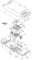
- the interface module shown in Fig. 1 consists essentially of two non-positively and / or positively joined housing parts 2, 4.
- the housing parts 2, 4 is preferably with a Provide mounting groove and / or other fasteners.
- the lower housing part 2 has a contacting device 6.
- the contacting device 6 serves, on the one hand, to contact or couple two bus lines 8 and / or to contact the / each bus line 8 with electronics which may be located in the upper housing part 4.
- the interface module has a guide device 10 which can be arranged in one of the two housing parts 2, 4.
- this guide device 10 can be moved in the level of the bus line (s) 8 to be connected such that the bus line (s) 8 can be arranged or connected within the interface module by moving the guide device 10 in at least two different directions in the bus line level.
- the guide device 10 is displaced on the one hand by a rotation about an imaginary axis of rotation X (shown in FIG. 1) and on the other hand a displacement by a spatial displacement along a longitudinal distance along an axis located in the Y-Y 'plane (only by longitudinal axes Y, Y 'indicated) conceivable.
- the contacting device 6 and the corresponding housing part 2 with its recesses 12b, 12c must be adapted to the respective embodiment.
- the guide device 10 and the corresponding housing part 2 and the contacting device 6 are designed such that in particular two directions of travel offset by 90 ° to one another can be realized for two connected bus lines 8.
- the contacting device 6 preferably consists of sheet-metal strip-like line means with knife-like contact tips 11.
- the contacting device 6 serves for contacting two-wire bus lines 8, in particular AS-i bus line (s), and consists essentially of two times two sheet metal strips, each of these strips at least has a contacting means (here, for example, terminal-like means for receiving contact pins) for the electrical connection with an electronics optionally arranged in the upper housing part 4, and at least two (here four) contact tips 11 for the electrical connection with a bus line 8.
- the contact tips 11 that are not required (depending on the direction of the bus line) are received by cavities in the guide device 10, so that damage to the bus line 8 or undesired contacting is excluded.
- the guide device 10 also has, in adaptation to the cross-sectional shape of the bus lines 8, at least one guide groove 12a (two shown here) for the or each bus line 8, with corresponding passage openings for the contact tips in the region of the guide groove (s) 12a in adaptation to the contact tips 11 are available.
- the guide grooves 12a have the profile of an AS-i bus line.
- the bus lines 8 in particular of form-coded bus lines such as AS-i bus lines, at least one of the two housing parts 2, 4 — here the lower housing part 2 — has at least four open-ended recesses 12b, 12c, which are in pairs opposite each other (shown with eight recesses 12b , 12c).
- the guide device 10 is shown as a molded part which can preferably be rotated about the axis of rotation X by 90 ° and can be inserted into a recess 14 within the housing part 2.
- Guide device 10 and recess 14 are form-coded such that the guide device 10 can only be inserted into the recess 14 in certain positions.
- the guide device 10 which is designed in particular as a square shaped part, has, for example, a coding lug 16 and the housing part 2 has a corresponding coding recess 18 in its recess 14.
- the guide device 10 can be fixed in the housing part 2, for example, by screwing, latching or simply by joining the two housing parts 2, 4 together.
- the bus lines 8 inserted in the guide device 10 can also be simply by means of an additional fastening element 20 which can be screwed and / or locked to the guide device 10 or the housing part 2 or without an additional fastening element 20 simply by joining the two housing parts 2, 4 or by direct locking of the Bus line 8 are fixed in the guide device 10.
- the guide device 10 shown preferably consists of the lower one Housing part 2 integrated, intersecting guide grooves 12a. How are shown, preferably two times two, in particular at an angle of 90 ° Degree crossing guide grooves 12a are provided.
- the management facility 10 has at least one of the two housing parts 2, 4 next to the recesses 12b in first wall areas for a first direction of the bus line 8, in two more opposite wall areas at least one additional to each Cross-sectional shape of the bus line 8 adapted, open-edge recess 12c.
- the Guide device 10 consists in particular of two times two, parallel to each other extending guide grooves 12a, which are in pairs at an angle of preferably Cross 90 degrees.
- each of the guide grooves 12a has Profile for receiving an AS-i bus line.
- the contacting device 6 is designed such that in all different course directions, the bus line (s) 8 can be contacted.
- a third embodiment of the interface module (FIG. 3), according to the invention mutually facing surfaces or partial surfaces of the two housing parts 2, 4 constructed in such a way that it runs parallel to the direction of the bus line (s) in several positions rotatably offset from each other can be joined.
- the lower housing part 2 is essentially cuboid, with a rectangular base trained, the contacting device here only with its knife-like Contact tips 11 can be seen.
- the contacting device is also parallel for two here Bus lines 8 running in relation to each other in one plane, these in turn two course directions, each rotated by an angle of 90 ° to one another can be arranged.
- the lower housing part 2 In addition to a groove for attachment to a top hat rail or the like the lower housing part 2 preferably additional means for connection to the any existing electronics on (in the form of terminal connections or the like).
- the electronics can be either in the upper or in the lower housing part 2, 4 be arranged. In the example shown, both the contacting device and also the electronics arranged in the lower housing part 2. For this reason, are omitted here also the contacting means for the electrical connection to the upper housing part 4.
- the upper housing part 4 is, for example, cuboid, with a square cross section formed and preferably on its side facing the lower housing part 2 two parallel guide grooves 12a.
- the guide grooves 12a are preferably adapted to the cross-section of an AS-i cable.
- the upper housing part 4 is non-positively and / or positively connected to the lower housing part 2, the two Parts 2, 4 are coded such that they are in particular in two, at an angle of 90 ° in the positions of the bus line are rotated against each other. Realized this mounting and coding is here through four mounting holes in the bottom Housing part 2, of which three of the holes have enlarged recesses for receiving have only two coding pins of the upper housing part 4. This is advantageous Execution that the upper housing part 4 then only due to the rotatability Must have recesses 12b or 12c in two opposite wall areas and no further recesses to be closed in addition with blind plates 13 for the second direction.
Landscapes
- Details Of Connecting Devices For Male And Female Coupling (AREA)
- Coupling Device And Connection With Printed Circuit (AREA)
- Multi-Conductor Connections (AREA)
- Connections By Means Of Piercing Elements, Nuts, Or Screws (AREA)
- Communication Control (AREA)
- Small-Scale Networks (AREA)
Abstract
In einer möglichen Ausführung der Erfindung ist eine, in einem der beiden Gehäuseteile (2, 4) anordenbare, in der Verlaufsebene der Busleitung (8) versetzbare, Führungseinrichtung (10) zur Aufnahme der Busleitung (8) vorhanden, wobei die Busleitung (8) durch Versetzen der Führungseinrichtung (10) in zumindest zwei unterschiedliche Richtungen innerhalb des Interface-Bausteins anordenbar ist.
Description

Derartige Koppelmodule haben sich in der Vergangenheit bereits bewährt und sollen lediglich weiterentwickelt werden.
Erfindungsgemäß ist die Führungseinrichtung versetz- oder verdrehbar in einem der beiden Gehäuseteile angeordnet derart, daß die angeschlossenen Busleitungen in mindestens zwei unterschiedliche Richtungen anschließbar sind.
In einer zweiten möglichen Ausführungsforrn weist der erfindungsgemäße Interface-Baustein eine Führungseinrichtung mit sich kreuzenden Führungsnuten für die Busleitungen auf. Dabei sind Gehäuseteil und Führungseinrichtung vorzugsweise einteilig ausgebildet.
Eine dritte Ausführung ist ebenfalls ohne separates Führungsteil ausgeführt. Hierbei sind die einander zugewandten Flächen beziehungsweise Teilflächen der beiden Gehäuseteile erfindungsgemäß derart aufgebaut, daß sie parallel zur Verlaufsrichtung der Busleitung(en) in mehreren, zueinander drehversetzten Positionen zusammenfügbar sind. Auch hier sind Führungseinrichtung und Gehäuseteil einteilig ausgebildet.
In einer bevorzugten Ausführungsform der Erfindung ist das Führungsteil und/oder jedes der Gehäuseteile derart ausgebildet, daß zwei Busleitungen in zumindest zwei um 90° Grad zueinander versetzten, in einer Ebene liegenden Verlaufsrichtungen anordenbar sind.
Die Busleitungen sind in einer Draufsicht auf den Interface-Baustein mit Vorteil mindestens in einer waagerechten und einer senkrechten Verlaufsrichtung an diesen anschließbar.
Aufwendige Busleitungsführungen können daher entfallen. Nicht zuletzt werden durch diese flexible Anschließbarkeit auch kürzere Anschlußwege und somit eine Einsparung von Busleitungsmaterial erreicht.
Weitere Vorteile der Erfindung sind in den Unteransprüchen und in der nachfolgenden Figurenbeschreibung enthalten. Es zeigen:
- Fig. 1-3
- den erfindungsgemäßen Interface-Baustein jeweils in einer möglichen Ausführungsform in schematischer Explosionsdarstellung.
Führungseinrichtung 10 und Aussparung 14 sind derart formcodiert, daß die Führungseinrichtung 10 nur in bestimmten Positionen in die Aussparung 14 einsetzbar ist. Hierfür weist die insbesondere als quadratisches Formteil ausgebildete Führungseinrichtung 10 beispielsweise eine Codiernase 16 und das Gehäuseteil 2 in seiner Aussparung 14 eine entsprechende Codierausnehmung 18 auf. Die Fixierung der Führungseinrichtung 10 im Gehäuseteil 2 kann beispielsweise durch Verschraubung, Verrastung oder einfach durch das Zusammenfügen der beiden Gehäuseteile 2, 4 erfolgen. Auch die in die Führungseinrichtung 10 eingelegten Busleitungen 8 können durch ein zusätzliches, mit der Führungseinrichtung 10 beziehungsweise dem Gehäuseteil 2 verschraub- und/oder verrastbares Befestigungselement 20 oder ohne zusätzliches Befestigungselement 20 einfach durch das Zusammenfügen der beiden Gehäuseteile 2, 4 oder durch direkte Verrastung der Busleitung 8 in der Führungseinrichtung 10 fixiert werden.
Claims (19)
- Interface-Baustein zum Anschluß an ein Bussystem, mit zwei kraft- und/oder formschlüssig zusammenfügbaren Gehäuseteilen (2, 4), wobei mindestens eines der beiden Gehäuseteile (2, 4) eine Kontaktierungseinrichtung (6) für die elektrische Kontaktierung zumindest einer zwischen den Gehäuseteilen (2, 4) anordenbaren Busleitung (8) des Bussystems mit einer gegebenenfalls vorhandenen Elektronik und/oder für die elektrische Kontaktierung von zwei oder mehr Busleitungen (8) untereinander aufweist und zumindest eines der beiden Gehäuseteile (2, 4) auf seiner dem anderen Gehäuseteil (4, 2) zugekehrten Seite, in zwei gegenüberliegenden Wandungsbereichen wenigstens eine, jeweils an die Querschnittsform der Busleitung (8) angepaßte, randoffene Ausnehmung (12b) aufweist, dadurch gekennzeichnet,daß eine, in einem der beiden Gehäuseteile (2, 4) anordenbare, in der Verlaufsebene der Busleitung (8) versetzbare, Führungseinrichtung (10) zur Aufnahme der Busleitung (8) vorhanden ist,daß in zwei weiteren gegenüberliegenden Wandungsbereichen zumindest eines der beiden Gehäuseteile (2, 4) mindestens jeweils eine zusätzliche, an die Querschnittsform der Busleitung (8) angepaßte, randoffene Ausnehmung (12c) vorhanden ist,und die Busleitung (8) durch Versetzen der Führungseinrichtung (10) in zumindest zwei unterschiedliche Richtungen innerhalb des Interface-Bausteins anordenbar ist, unddaß die Kontaktierungseinrichtung (6) derart ausgebildet ist, daß in allen unterschiedlichen Verlaufsrichtungen die Busleitung (8) kontaktierbar ist.
- Interface-Baustein nach Anspruch 1,
dadurch gekennzeichnet, daß eines der beiden Gehäuseteile (2, 4) eine Aussparung (14) zur Aufnahme der Führungseinrichtung (10) aufweist. - Interface-Baustein nach Anspruch 1 oder 2,
dadurch gekennzeichnet, daß die Führungseinrichtung (10) als rechteckiges Formteil ausgebildet ist. - Interface-Baustein nach einem der vorstehenden Ansprüche,
dadurch gekennzeichnet, daß die Führungseinrichtung (10) in mindestens zwei zueinander verdrehten Positionen in einem der beiden Gehäuseteile (2, 4) anordenbar ist. - Interface-Baustein nach einem der vorstehenden Ansprüche,
dadurch gekennzeichnet, daß die Führungseinrichtung (10) und eines der Gehäuseteile (2, 4) derart ausgebildet sind, daß sie um 90° Grad zueinander versetz- oder verdrehbar sind, die Führungseinrichtung (10) mindestens eine randoffene Führungsnut (12a) aufweist und zumindest eines der beiden Gehäuseteile (2, 4) in Anpassung an die Führungsnut (12a) vier, um 90° Grad zueinander versetzt angeordnete, randoffene Ausnehmungen (12b) aufweist. - Interface-Baustein nach einem der vorstehenden Ansprüche,
dadurch gekennzeichnet, daß die Führungseinrichtung (10) und eines der Gehäuseteile (2, 4) derart ausgebildet sind, daß sie um 90° Grad zueinander versetz- oder verdrehbar sind, die Führungseinrichtung (10) zwei randoffene Führungsnuten (12a) aufweist und zumindest eines der beiden Gehäuseteile (2, 4) in Anpassung an die Führungsnuten (12a) vier mal zwei, paarweise um 90° Grad zueinander versetzt angeordnete, randoffene Ausnehmungen (12b) aufweist. - Interface-Baustein nach einem der vorstehenden Ansprüche,
dadurch gekennzeichnet, daß die Führungseinrichtung (10) und die Aussparung (14) formcodiert sind, so daß die Führungseinrichtung (10) nur in bestimmten Positionen in die Aussparung (14) einfügbar ist. - Interface-Baustein zum Anschluß an ein Bussystem, mit zwei kraft- und/oder formschlüssig zusammenfügbaren Gehäuseteilen (2, 4), wobei mindestens eines der beiden Gehäuseteile (2, 4) eine Kontaktierungseinrichtung (6) für die elektrische Kontaktierung zumindest einer zwischen den Gehäuseteilen (2, 4) anordenbaren Busleitung (8) des Bussystems mit einer gegebenenfalls vorhandenen Elektronik und/oder für die elektrische Kontaktierung von zwei oder mehr Busleitungen (8) untereinander aufweist und zumindest eines der beiden Gehäuseteile (2, 4) auf seiner dem anderen Gehäuseteil (4, 2) zugekehrten Seite, in zwei gegenüberliegenden Wandungsbereichen Wenigstens eine, jeweils an die Querschnittsform der Busleitung (8) angepaßte, randoffene Ausnehmung (12b) aufweist, dadurch gekennzeichnet,daß eines der beiden Gehäuseteile (2, 4) eine Führungseinrichtung (10) mit sich kreuzenden Führungsnuten (12 a) zur Aufnahme der Busleitung (8) in zumindest zwei unterschiedlichen, in einer Ebene liegenden Verlaufsrichtungen für die mindestens eine Busleitung (8) aufweist,daß in zwei weiteren gegenüberliegenden Wandungsbereichen zumindest eines der beiden Gehäuseteile (2, 4) mindestens jeweils eine zusätzliche, an die Querschnittsform der Busleitung (8) angepaßte, randoffene Ausnehmung (12c) vorhanden ist,daß die Kontaktierungseinrichtung (6) derart ausgebildet ist, daß in allen unterschiedlichen Verlaufsrichtungen die Busleitung (8) kontaktierbar ist.
- Interface-Baustein nach Anspruch 8,
dadurch gekennzeichnet, daß die Führungseinrichtung (10) einteilig mit einem der Gehäuseteile (2, 4) ausgebildet ist. - Interface-Baustein nach Anspruch 8 oder 9,
dadurch gekennzeichnet, daß die Führungseinrichtung (10) zwei sich unter einem Winkel von 90° Grad kreuzende Führungsnuten (12a) aufweist und zumindest eines der beiden Gehäuseteile (2, 4) in Anpassung an die Führungsnuten (12a) vier, um 90° Grad zueinander versetzt angeordnete, randoffene Ausnehmungen (12b) aufweist. - Interface-Baustein nach Anspruch 8 oder 9,
dadurch gekennzeichnet, daß die Führungseinrichtung (10) zwei mal zwei parallel zueinander verlaufende, sich paarweise unter einem Winkel von 90° Grad kreuzende Führungsnuten (12a) aufweist und zumindest eines der beiden Gehäuseteile (2, 4) in Anpassung an die Führungsnut (12a) vier mal zwei, paarweise um 90° Grad zueinander versetzt angeordnete, randoffene Ausnehmungen (12b) aufweist. - Interface-Baustein nach einem der vorstehenden Ansprüche,
dadurch gekennzeichnet, daß die Führungsnut (12a) das Profil einer AS-i Busleitung aufweist. - Interface-Baustein nach einem der vorstehenden Ansprüche,
dadurch gekennzeichnet, daß die Gehäuseteile (2, 4) in Busleitungsebene gesehen einen quadratischen Querschnitt aufweisen. - Interface-Baustein zum Anschluß an ein Bussystem, mit zwei kraft- und/oder formschlüssig zusammenfügbaren Gehäuseteilen (2, 4), wobei mindestens eines der beiden Gehäuseteile (2, 4) eine Kontaktierungseinrichtung (6) für die elektrische Kontaktierung zumindest einer zwischen den Gehäuseteilen (2, 4) anordenbaren Busleitung (8) des Bussystems mit einer gegebenenfalls vorhandenen Elektronik und/oder für die elektrische Kontaktierung von zwei oder mehr Busleitungen (8) untereinander aufweist und zumindest eines der beiden Gehäuseteile (2, 4) auf seiner dem anderen Gehäuseteil (4, 2) zugekehrten Seite, in zwei gegenüberliegenden Wandungsbereichen wenigstens eine, jeweils an die Querschnittsform der Busleitung (8) angepaßte, randoffene Ausnehmung (12b) aufweist,
dadurch gekennzeichnet,daß die einander zugewandten Flächen beziehungsweise Teilflächen der beiden Gehäuseteile (2, 4) derart aufgebaut sind, daß sie parallel zur Verlaufsrichtung der Busleitung (8) in mehreren, zueinander drehversetzten Positionen zusammenfügbar sind, unddaß die Kontaktierungseinrichtung (6) derart ausgebildet ist, daß in allen unterschiedlichen Verlaufsrichtungen beziehungsweise Positionen die Busleitung (8) kontaktierbar ist. - Interface-Baustein nach einem der vorstehenden Ansprüche,
dadurch gekennzeichnet, daß das eines der beiden Gehäuseteile (2, 4) die Kontaktierungseinrichtung (6) und das andere der beiden Gehäuseteile (2, 4) eine elektrische Schaltungsanordnung aufweist, wobei die Kontaktierungseinrichtung (6) einerseits und die Schaltungsanordnung andererseits Kontaktmittel aufweisen, die in Anpassung an die Gehäuseteile (2, 4) die jeweilige elektrische Verbindung zwischen Busleitung (8) und Schaltungsanordnung bilden. - Interface-Baustein nach einem der vorstehenden Ansprüche,
dadurchgekennzeichnet, daß die Kontaktierungseinrichtung (6) und die Schaltungsanordnung gemeinsam in einem der Gehäuseteile (2, 4) angeordnet sind. - Interface-Baustein nach einem der vorstehenden Ansprüche,
dadurch gekennzeichnet, daß die Kontaktierungseinrichtung (6) aus blechstreifenartigen Leitungsmitteln besteht, die zur Kontaktierung mit der beziehungsweise jeder Busleitung (8) messerartige Kontaktspitzen (11) aufweisen. - Interface-Baustein nach einem der vorstehenden Ansprüche,
dadurch gekennzeichnet, daß der die Schaltungsanordnung aufweisende Gehäuseteil (2, 4) zusätzliche Mittel zum Anschluß an die Schaltungsanordnung aufweist. - Interface-Baustein nach einem der vorstehenden Ansprüche,
dadurch gekennzeichnet, daß zwischen den beiden Gehäuseteilen (2, 4), in deren Randbereich, umfänglich ein Dichtungselement angeordnet ist.
Applications Claiming Priority (2)
| Application Number | Priority Date | Filing Date | Title |
|---|---|---|---|
| DE19714637 | 1997-04-09 | ||
| DE19714637A DE19714637C1 (de) | 1997-04-09 | 1997-04-09 | Interface-Baustein für den Anschluß an ein Bussystem |
Publications (3)
| Publication Number | Publication Date |
|---|---|
| EP0871245A2 true EP0871245A2 (de) | 1998-10-14 |
| EP0871245A3 EP0871245A3 (de) | 2000-01-19 |
| EP0871245B1 EP0871245B1 (de) | 2004-09-22 |
Family
ID=7825900
Family Applications (1)
| Application Number | Title | Priority Date | Filing Date |
|---|---|---|---|
| EP98106435A Expired - Lifetime EP0871245B1 (de) | 1997-04-09 | 1998-04-08 | Interface-Baustein für den Anschluss an ein Bussystem |
Country Status (3)
| Country | Link |
|---|---|
| EP (1) | EP0871245B1 (de) |
| AT (1) | ATE277433T1 (de) |
| DE (2) | DE19714637C1 (de) |
Cited By (5)
| Publication number | Priority date | Publication date | Assignee | Title |
|---|---|---|---|---|
| FR2825522A1 (fr) * | 2001-06-05 | 2002-12-06 | Applic Electro Mecaniques | Boitier de raccordement electrique a percement d'isolant, contact utilise dans un tel boitier, et ligne d'alimentation electrique comportant de tels boitiers |
| DE10221477A1 (de) * | 2002-05-15 | 2004-03-04 | Phoenix Contact Gmbh & Co. Kg | Verbindungseinrichtung zur elektrischen und mechanischen Verbindung von mehradrigen isolierten Leitern |
| DE102006001371A1 (de) * | 2006-01-11 | 2007-07-12 | Adc Gmbh | Anschlussmodul zum Verbinden mindestens zweier Adern |
| USD587201S1 (en) | 2006-01-11 | 2009-02-24 | Adc Gmbh | Connection module |
| US7695308B2 (en) | 2008-03-19 | 2010-04-13 | Adc Gmbh | Connection module |
Family Cites Families (7)
| Publication number | Priority date | Publication date | Assignee | Title |
|---|---|---|---|---|
| DE885105C (de) * | 1951-06-27 | 1953-08-03 | Paul Jordan | Gehaeuse, insbesondere Abzweig- oder Verbindungsdose |
| CA2009282C (en) * | 1989-02-06 | 2001-01-23 | Paul Lindsay Rishworth | Multi conductor electrical cable connector |
| DE4005351A1 (de) * | 1990-02-20 | 1991-08-22 | Minnesota Mining & Mfg | Verbindung fuer mindestens ein paar isolierter leiter |
| DE4305544C2 (de) * | 1993-02-24 | 1997-08-21 | Staiger Steuerungstech | Einrichtung für einen Aktor |
| DE4320327C1 (de) * | 1993-04-13 | 1994-06-01 | Siemens Ag | Aktuatoren oder Sensoren zum Anschluß an eine Busleitung |
| US5722852A (en) * | 1993-04-14 | 1998-03-03 | Siemens Aktiengesellschaft | Module for the connection of actuator and/or sensors |
| DE19504013C1 (de) * | 1995-02-07 | 1996-07-18 | Lumberg Karl Gmbh & Co | Anschlußvorrichtung zur wahlfreien Herstellung eines wiederverwendbaren elektrischen Anschlusses bzw. Abgriffs an mehradrigen elektrischen Leitungen |
-
1997
- 1997-04-09 DE DE19714637A patent/DE19714637C1/de not_active Expired - Fee Related
-
1998
- 1998-04-08 AT AT98106435T patent/ATE277433T1/de not_active IP Right Cessation
- 1998-04-08 DE DE59811975T patent/DE59811975D1/de not_active Expired - Fee Related
- 1998-04-08 EP EP98106435A patent/EP0871245B1/de not_active Expired - Lifetime
Cited By (8)
| Publication number | Priority date | Publication date | Assignee | Title |
|---|---|---|---|---|
| FR2825522A1 (fr) * | 2001-06-05 | 2002-12-06 | Applic Electro Mecaniques | Boitier de raccordement electrique a percement d'isolant, contact utilise dans un tel boitier, et ligne d'alimentation electrique comportant de tels boitiers |
| DE10221477A1 (de) * | 2002-05-15 | 2004-03-04 | Phoenix Contact Gmbh & Co. Kg | Verbindungseinrichtung zur elektrischen und mechanischen Verbindung von mehradrigen isolierten Leitern |
| DE10221477B4 (de) * | 2002-05-15 | 2008-12-24 | Phoenix Contact Gmbh & Co. Kg | Verbindungseinrichtung zur elektrischen und mechanischen Verbindung von mehradrigen isolierten Leitern |
| DE102006001371A1 (de) * | 2006-01-11 | 2007-07-12 | Adc Gmbh | Anschlussmodul zum Verbinden mindestens zweier Adern |
| USD587201S1 (en) | 2006-01-11 | 2009-02-24 | Adc Gmbh | Connection module |
| USD587200S1 (en) | 2006-01-11 | 2009-02-24 | Adc Gmbh | Base for connection module |
| USD587651S1 (en) | 2006-01-11 | 2009-03-03 | Adc Gmbh | Insert for connection module |
| US7695308B2 (en) | 2008-03-19 | 2010-04-13 | Adc Gmbh | Connection module |
Also Published As
| Publication number | Publication date |
|---|---|
| EP0871245A3 (de) | 2000-01-19 |
| ATE277433T1 (de) | 2004-10-15 |
| DE19714637C1 (de) | 1998-10-01 |
| EP0871245B1 (de) | 2004-09-22 |
| DE59811975D1 (de) | 2004-10-28 |
Similar Documents
| Publication | Publication Date | Title |
|---|---|---|
| DE3226199C2 (de) | ||
| DE69508396T2 (de) | Schieneneinheit | |
| DE69600047T2 (de) | Zusammensetzbare elektrische Schnittstellenvorrichtung | |
| DE2701703C3 (de) | Haltevorrichtung für Druckschaltungskarten | |
| DE3331594C2 (de) | ||
| DE3608046A1 (de) | Baugruppentraeger fuer elektronische und/oder elektromechanische einschubbaugruppen | |
| EP1239544A2 (de) | Elektrisches Gerät mit Busleiterabschnitt | |
| DE9412465U1 (de) | Modulares Steckverbindungssystem | |
| EP0993171A2 (de) | Aufnahmegehäuse einer Türstation einer Türsprechanlage | |
| EP0871245B1 (de) | Interface-Baustein für den Anschluss an ein Bussystem | |
| EP0929135A2 (de) | Multifunktionsadapter für eine Anzahl von Stromsammelschienen eines Sammelschienensystems | |
| DE9304929U1 (de) | Schirmeinrichtung für rechteckige Kabelstecker | |
| DE19703751C1 (de) | Bauteilgruppe | |
| DE9104134U1 (de) | Verbessertes vertikales Sortiersystem | |
| EP0762582A1 (de) | Adapter für Sammelschienensysteme | |
| EP2831970B1 (de) | Systemmodul für die gebäude-elektroinstallationstechnik und türkommunikationstechnik | |
| DE29916302U1 (de) | Busleiterabschnitt für ein elektrisches Gerät | |
| EP0457254A2 (de) | Vorrichtung zur Halterung elektrotechnischer, insbesondere nachrichtentechnischer Bauteile | |
| DE2802643A1 (de) | Steckverbinder | |
| EP1129461B1 (de) | Relais mit koppelelement | |
| DE20019792U1 (de) | Steckverbinder-Gehäuse mit Kodiereinrichtung | |
| DE2746319A1 (de) | Befestigungs- und schaltvorrichtung | |
| DE69607307T2 (de) | Abstandshaltermodul, insbesondere für modulare elektrische Geräte | |
| DE10205614B4 (de) | Anschlussadapter | |
| EP1593976A2 (de) | Zählerschrank zur Aufnahme wenigstens eines Stromzählers |
Legal Events
| Date | Code | Title | Description |
|---|---|---|---|
| PUAI | Public reference made under article 153(3) epc to a published international application that has entered the european phase |
Free format text: ORIGINAL CODE: 0009012 |
|
| AK | Designated contracting states |
Kind code of ref document: A2 Designated state(s): AT BE CH DE DK ES FI FR GB IE IT LI NL PT SE |
|
| AX | Request for extension of the european patent |
Free format text: AL;LT;LV;MK;RO;SI |
|
| RAP1 | Party data changed (applicant data changed or rights of an application transferred) |
Owner name: MOELLER GMBH |
|
| PUAL | Search report despatched |
Free format text: ORIGINAL CODE: 0009013 |
|
| AK | Designated contracting states |
Kind code of ref document: A3 Designated state(s): AT BE CH CY DE DK ES FI FR GB GR IE IT LI LU MC NL PT SE |
|
| AX | Request for extension of the european patent |
Free format text: AL;LT;LV;MK;RO;SI |
|
| 17P | Request for examination filed |
Effective date: 19991220 |
|
| AKX | Designation fees paid |
Free format text: AT BE CH DE DK ES FI FR GB IE IT LI NL PT SE |
|
| RIC1 | Information provided on ipc code assigned before grant |
Free format text: 7H 01R 12/08 A, 7H 01R 4/24 B |
|
| 17Q | First examination report despatched |
Effective date: 20020918 |
|
| GRAP | Despatch of communication of intention to grant a patent |
Free format text: ORIGINAL CODE: EPIDOSNIGR1 |
|
| RIC1 | Information provided on ipc code assigned before grant |
Ipc: 7H 01R 4/24 B Ipc: 7H 01R 12/08 A |
|
| GRAS | Grant fee paid |
Free format text: ORIGINAL CODE: EPIDOSNIGR3 |
|
| GRAA | (expected) grant |
Free format text: ORIGINAL CODE: 0009210 |
|
| AK | Designated contracting states |
Kind code of ref document: B1 Designated state(s): AT BE CH DE DK ES FI FR GB IE IT LI NL PT SE |
|
| PG25 | Lapsed in a contracting state [announced via postgrant information from national office to epo] |
Ref country code: NL Free format text: LAPSE BECAUSE OF FAILURE TO SUBMIT A TRANSLATION OF THE DESCRIPTION OR TO PAY THE FEE WITHIN THE PRESCRIBED TIME-LIMIT Effective date: 20040922 Ref country code: IE Free format text: LAPSE BECAUSE OF FAILURE TO SUBMIT A TRANSLATION OF THE DESCRIPTION OR TO PAY THE FEE WITHIN THE PRESCRIBED TIME-LIMIT Effective date: 20040922 Ref country code: GB Free format text: LAPSE BECAUSE OF FAILURE TO SUBMIT A TRANSLATION OF THE DESCRIPTION OR TO PAY THE FEE WITHIN THE PRESCRIBED TIME-LIMIT Effective date: 20040922 Ref country code: FI Free format text: LAPSE BECAUSE OF FAILURE TO SUBMIT A TRANSLATION OF THE DESCRIPTION OR TO PAY THE FEE WITHIN THE PRESCRIBED TIME-LIMIT Effective date: 20040922 |
|
| REG | Reference to a national code |
Ref country code: GB Ref legal event code: FG4D Free format text: NOT ENGLISH |
|
| REG | Reference to a national code |
Ref country code: CH Ref legal event code: EP |
|
| REG | Reference to a national code |
Ref country code: IE Ref legal event code: FG4D Free format text: GERMAN |
|
| REF | Corresponds to: |
Ref document number: 59811975 Country of ref document: DE Date of ref document: 20041028 Kind code of ref document: P |
|
| REG | Reference to a national code |
Ref country code: CH Ref legal event code: NV Representative=s name: DTS ZUERICH |
|
| PG25 | Lapsed in a contracting state [announced via postgrant information from national office to epo] |
Ref country code: DK Free format text: LAPSE BECAUSE OF FAILURE TO SUBMIT A TRANSLATION OF THE DESCRIPTION OR TO PAY THE FEE WITHIN THE PRESCRIBED TIME-LIMIT Effective date: 20041222 |
|
| PG25 | Lapsed in a contracting state [announced via postgrant information from national office to epo] |
Ref country code: ES Free format text: LAPSE BECAUSE OF FAILURE TO SUBMIT A TRANSLATION OF THE DESCRIPTION OR TO PAY THE FEE WITHIN THE PRESCRIBED TIME-LIMIT Effective date: 20050102 |
|
| REG | Reference to a national code |
Ref country code: SE Ref legal event code: TRGR |
|
| NLV1 | Nl: lapsed or annulled due to failure to fulfill the requirements of art. 29p and 29m of the patents act | ||
| PG25 | Lapsed in a contracting state [announced via postgrant information from national office to epo] |
Ref country code: AT Free format text: LAPSE BECAUSE OF NON-PAYMENT OF DUE FEES Effective date: 20050408 |
|
| PGFP | Annual fee paid to national office [announced via postgrant information from national office to epo] |
Ref country code: SE Payment date: 20050412 Year of fee payment: 8 Ref country code: FR Payment date: 20050412 Year of fee payment: 8 Ref country code: CH Payment date: 20050412 Year of fee payment: 8 |
|
| PGFP | Annual fee paid to national office [announced via postgrant information from national office to epo] |
Ref country code: DE Payment date: 20050418 Year of fee payment: 8 |
|
| GBV | Gb: ep patent (uk) treated as always having been void in accordance with gb section 77(7)/1977 [no translation filed] |
Effective date: 20040922 |
|
| REG | Reference to a national code |
Ref country code: IE Ref legal event code: FD4D |
|
| PG25 | Lapsed in a contracting state [announced via postgrant information from national office to epo] |
Ref country code: BE Free format text: LAPSE BECAUSE OF NON-PAYMENT OF DUE FEES Effective date: 20050430 |
|
| PLBE | No opposition filed within time limit |
Free format text: ORIGINAL CODE: 0009261 |
|
| STAA | Information on the status of an ep patent application or granted ep patent |
Free format text: STATUS: NO OPPOSITION FILED WITHIN TIME LIMIT |
|
| ET | Fr: translation filed | ||
| 26N | No opposition filed |
Effective date: 20050623 |
|
| BERE | Be: lapsed |
Owner name: *MOELLER G.M.B.H. Effective date: 20050430 |
|
| PG25 | Lapsed in a contracting state [announced via postgrant information from national office to epo] |
Ref country code: SE Free format text: LAPSE BECAUSE OF NON-PAYMENT OF DUE FEES Effective date: 20060409 |
|
| PG25 | Lapsed in a contracting state [announced via postgrant information from national office to epo] |
Ref country code: LI Free format text: LAPSE BECAUSE OF NON-PAYMENT OF DUE FEES Effective date: 20060430 Ref country code: CH Free format text: LAPSE BECAUSE OF NON-PAYMENT OF DUE FEES Effective date: 20060430 |
|
| PGFP | Annual fee paid to national office [announced via postgrant information from national office to epo] |
Ref country code: IT Payment date: 20060430 Year of fee payment: 9 |
|
| PG25 | Lapsed in a contracting state [announced via postgrant information from national office to epo] |
Ref country code: DE Free format text: LAPSE BECAUSE OF NON-PAYMENT OF DUE FEES Effective date: 20061101 |
|
| REG | Reference to a national code |
Ref country code: CH Ref legal event code: PL |
|
| EUG | Se: european patent has lapsed | ||
| REG | Reference to a national code |
Ref country code: FR Ref legal event code: ST Effective date: 20061230 |
|
| BERE | Be: lapsed |
Owner name: *MOELLER G.M.B.H. Effective date: 20050430 |
|
| PG25 | Lapsed in a contracting state [announced via postgrant information from national office to epo] |
Ref country code: PT Free format text: LAPSE BECAUSE OF NON-PAYMENT OF DUE FEES Effective date: 20050222 |
|
| PG25 | Lapsed in a contracting state [announced via postgrant information from national office to epo] |
Ref country code: FR Free format text: LAPSE BECAUSE OF NON-PAYMENT OF DUE FEES Effective date: 20060502 |
|
| PG25 | Lapsed in a contracting state [announced via postgrant information from national office to epo] |
Ref country code: IT Free format text: LAPSE BECAUSE OF NON-PAYMENT OF DUE FEES Effective date: 20070408 |