EP0871403B1 - Vorrichtung zur durchführung von manipulationen im menschlichen körper und insbesondere im uterus - Google Patents
Vorrichtung zur durchführung von manipulationen im menschlichen körper und insbesondere im uterus Download PDFInfo
- Publication number
- EP0871403B1 EP0871403B1 EP96942261A EP96942261A EP0871403B1 EP 0871403 B1 EP0871403 B1 EP 0871403B1 EP 96942261 A EP96942261 A EP 96942261A EP 96942261 A EP96942261 A EP 96942261A EP 0871403 B1 EP0871403 B1 EP 0871403B1
- Authority
- EP
- European Patent Office
- Prior art keywords
- hook
- bell
- hooks
- rod
- shaft
- Prior art date
- Legal status (The legal status is an assumption and is not a legal conclusion. Google has not performed a legal analysis and makes no representation as to the accuracy of the status listed.)
- Expired - Lifetime
Links
- 210000004291 uterus Anatomy 0.000 title claims description 6
- 230000002093 peripheral effect Effects 0.000 claims description 4
- 238000006073 displacement reaction Methods 0.000 claims 1
- 238000004140 cleaning Methods 0.000 description 1
- 238000011161 development Methods 0.000 description 1
- 230000018109 developmental process Effects 0.000 description 1
- 238000001839 endoscopy Methods 0.000 description 1
- 238000002357 laparoscopic surgery Methods 0.000 description 1
- 230000001954 sterilising effect Effects 0.000 description 1
Images

Classifications
-
- A—HUMAN NECESSITIES
- A61—MEDICAL OR VETERINARY SCIENCE; HYGIENE
- A61B—DIAGNOSIS; SURGERY; IDENTIFICATION
- A61B17/00—Surgical instruments, devices or methods
- A61B17/42—Gynaecological or obstetrical instruments or methods
- A61B17/4241—Instruments for manoeuvring or retracting the uterus, e.g. during laparoscopic surgery
-
- A—HUMAN NECESSITIES
- A61—MEDICAL OR VETERINARY SCIENCE; HYGIENE
- A61B—DIAGNOSIS; SURGERY; IDENTIFICATION
- A61B17/00—Surgical instruments, devices or methods
- A61B17/34—Trocars; Puncturing needles
- A61B2017/348—Means for supporting the trocar against the body or retaining the trocar inside the body
- A61B2017/3482—Means for supporting the trocar against the body or retaining the trocar inside the body inside
- A61B2017/3484—Anchoring means, e.g. spreading-out umbrella-like structure
-
- A—HUMAN NECESSITIES
- A61—MEDICAL OR VETERINARY SCIENCE; HYGIENE
- A61B—DIAGNOSIS; SURGERY; IDENTIFICATION
- A61B90/00—Instruments, implements or accessories specially adapted for surgery or diagnosis and not covered by any of the groups A61B1/00 - A61B50/00, e.g. for luxation treatment or for protecting wound edges
- A61B90/30—Devices for illuminating a surgical field, the devices having an interrelation with other surgical devices or with a surgical procedure
Definitions
- the invention relates to a device for performing of manipulations in the human body and especially in the uterus according to the preamble of the claim 1.
- a device for carrying out manipulations in the human body and especially in the uterus according to the The preamble of claim 1 is from the US-PS 4,633,869 known.
- the sliding element of this device that is slidable on the shaft in its longitudinal direction has an extension at the distal end that extends out flexible material.
- the so trained Sliding element is usually used on an outer body surface to be put on to fix the pliers. This part of the instrument is not human Body can be used.
- the invention has for its object a generic Device for carrying out manipulations in the human body and especially in the uterus to further develop that it can be used in the body and even in cases where the to be manipulated Dodge tissue parts sideways, the desired manipulation can be executed.
- the instrument according to the invention can then be used as follows:
- the respective tissue parts can be manipulated by moving the sliding element provided on the shaft with the approximately bell-shaped extension, and by actuating the distally provided elements, for example the hook or hooks.
- the distally provided elements for example the hook or hooks.
- the sliding element has a lighting device on, the light emission at the peripheral edge of the bell-shaped extension is provided. This is it is possible to manipulate the tissue section to be manipulated if necessary in addition to endoscope lighting illuminate. Most of all, it is possible to do laparoscopy to determine the position of the bell rim. Due to the lighting, the position of the Sliding element visible to the surgeon.
- Extension has the shape of a hemisphere Advantage that the extension when removing or when withdrawing, not in the tissue or body opening can get caught.
- a drive unit for the sliding element is, which has a handwheel, the one in a longitudinal groove guided ball moved over a threaded groove. In order to the operator must move the Only slide the sliding element by hand.
- the hook element can have at least three, preferably four hooks, which are folded in when the handle sticks are open, and which are folded out in the direction of the distal end by the rod acting as a pull rod by closing the handle pieces. (Claim 5)
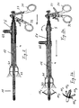
- Fig. 1 shows the essential components of an inventive Device for carrying out manipulations in the human body, which is particularly known as Uterine manipulator is suitable.
- the device has a Hook unit 1, which has a hook element at its distal end 11 carries, which is explained in more detail below will be.
- the hook element 11 is via an (actuating) rod 12 with the proximal end of the uterine manipulator connected.
- a ball 13 is provided, its function below will be explained.
- the hook unit 1 is in one Shaft 2 of the device used. This is through the Arrow a symbolizes.
- the connection between the hook unit 1 and shaft 2 are made using a bayonet connection. Spring-loaded at the proximal end to prevent rotation Proceed half shells, such as in the EP-A-0 688 187.
- a handle 3 With the proximal end of the shaft 2 is a handle 3 with two handles 31 and 32 and a catch 33 - for example through a screw connection - but also over any other suitable connection - connected (see arrow b). Due to the detent 33, the handles 31 and 32 are in one definable position.
- the ball 13 is through a lockable ball connection with the movable handle 32 of the handle 3 connected.
- a sliding element 4 which a bell-shaped extension 41 at its distal end having.
- a nozzle 42 for connecting a lighting device intended. That emitted by the lighting device Light is shone through (known in endoscopy) Light guide led to the distal end. The light emission is provided in the peripheral edge 43 of the extension 41.
- the sliding element 4 is before the hook unit is connected 1 with the shaft 2 placed on the shaft 2 (arrow c). Then the handle 3 with the outer shaft 2 and the proximal end of the rod 12.
- FIGS. 2 and 3 show the one designed according to the invention Uterine manipulator shown assembled:
- the hook element 11, which - as shown in FIG. 3b - has four hooks 11 1 to 11 4 is designed so that the hooks are folded in when the handles 31 and 32 are open. By closing or compressing the grips, the hooks are folded out in the direction of the distal end by the rod 12 acting as a pull rod.
- the sliding element 4 is displaced in the direction of the longitudinal axis of the shaft 2 by turning a handwheel 5.
- a ball 51 is provided which is guided in a longitudinal groove and which is displaced via a threaded groove in the direction of the longitudinal axis of the instrument or the manipulator.
- the manipulation carried out with the hooks 11 1 to 11 4 can be supported by pulling the sliding element 4 back and forth.
- illuminating light emerges from the peripheral edge of the bell-shaped extension 41 in order, for example, to be able to determine the position of the bell edge of the vaginally inserted instrument laparoscopically.
Landscapes
- Health & Medical Sciences (AREA)
- Surgery (AREA)
- Life Sciences & Earth Sciences (AREA)
- Biomedical Technology (AREA)
- Medical Informatics (AREA)
- Reproductive Health (AREA)
- Pregnancy & Childbirth (AREA)
- Engineering & Computer Science (AREA)
- Gynecology & Obstetrics (AREA)
- Heart & Thoracic Surgery (AREA)
- Nuclear Medicine, Radiotherapy & Molecular Imaging (AREA)
- Molecular Biology (AREA)
- Animal Behavior & Ethology (AREA)
- General Health & Medical Sciences (AREA)
- Public Health (AREA)
- Veterinary Medicine (AREA)
- Surgical Instruments (AREA)
- Endoscopes (AREA)
Description
Das erfindungsgemäße Instrument kann danach wie folgt eingesetzt werden:
Durch Verschieben des auf dem Schaft vorgesehenen Gleitelements mit der angenähert glockenförmig ausgebildeten Erweiterung, und durch Betätigen der distal vorgesehenen Elemente, also beispielsweise des oder der Haken, können die jeweiligen Gewebeteile manipuliert werden. Insbesondere ist es möglich, mit dem Gleitelement das Gewebe in Zusammenwirken mit dem oder den Haken "festzuhalten" .
(Anspruch 5)
- Fig. 1
- eine Einzelteildarstellung eines erfindungsgemäß ausgebildeten Uterusmanipulators,
- Fig. 2
- den zusammengebauten Uterusmanipulator mit geschlossenem Hakenelement,
- Fig. 3a
- den in Figur 2 dargestellten Uterusmanipulator mit geöffnetem Hakenelement, und
- Fig. 3b
- eine perspektivische Darstellung des Hakenelements mit vier Haken.
Claims (7)
- Vorrichtung zur Durchführung von Manipulationen im menschlichen Körper und insbesondere im Uterus, mit einem Hakenelement (11), das wenigstens einen Haken aufweist, der über eine Stange (12), die in einem Schaft (2) geführt ist, mit einem am proximalen Ende vorgesehenen Griffstück (3) verbunden ist, so dass er aus- und einschwenkbar ist, und einem Gleitelement (41), das auf dem Schaft (2) in dessen Längsrichtung verschiebbar geführt ist, und das an seinem distalen Ende eine angenähert glockenförmige Erweiterung (41) aufweist,
dadurch gekennzeichnet, dass die glockenförmige Erweiterung am distalen Ende des Gleitelements (41) derart ausgebildet ist, dass sie in den menschlichen Körper einfuhrbar ist und dort im Zusammenwirken mit dem oder den Haken (111, 112, 113, 114) eine Manipulation der zu manipulierenden Gewebeteile erlaubt. - Vorrichtung nach Anspruch 1,
dadurch gekennzeichnet, dass das Gleitelement (41) eine Beleuchtungseinrichtung aufweist, deren Lichtaustritt im Umfangsrand (43) der glockenförmigen Erweiterung (41) vorgesehen ist. - Vorrichtung nach einem der Ansprüche 1 bis 2,
dadurch gekennzeichnet, dass die glockenförmige Erweiterung (41) in etwa die Form einer Halbkugel hat. - Vorrichtung nach einem der Ansprüche 1 bis 3,
dadurch gekennzeichnet, dass eine Antriebseinheit für das Gleitelement (4) vorgesehen ist, die ein Handrad (5) aufweist, das eine in einer Längsnut geführte Kugel (51) über eine gewindeförmige Nut bewegt. - Vorrichtung nach einem der Ansprüche 1 bis 4,
dadurch gekennzeichnet, dass das Hakenelement (11) wenigstens drei, bevorzugt vier Haken (111, 112, 113, 114) aufweist, die bei geöffneten Griffstücken (31, 32) eingeklappt sind, und die durch das Schließen der Griffstücke (31, 32) durch die als Zugstange wirkende Stange (12) in Richtung auf das distale Ende ausgeklappt werden. - Vorrichtung nach einem der Ansprüche 1 bis 5,
dadurch gekennzeichnet, dass die Stange (12), mittels derer die Haken (111, 112, 113, 114) betätigt werden, mit den Griffstücken (31, 32) lösbar verbunden ist. - Vorrichtung nach einem der Ansprüche 4 bis 6,
dadurch gekennzeichnet, dass das Hakenelement (11), der Schaft (2), der Griff (3) und gegebenenfalls die Antriebseinheit voneinander trennbar sind.
Applications Claiming Priority (3)
| Application Number | Priority Date | Filing Date | Title |
|---|---|---|---|
| DE19543576 | 1995-11-22 | ||
| DE19543576A DE19543576A1 (de) | 1995-11-22 | 1995-11-22 | Vorrichtung zur Durchführung von Manipulationen im menschlichen Körper und insbesondere im Uterus |
| PCT/DE1996/002251 WO1997018757A1 (de) | 1995-11-22 | 1996-11-22 | Vorrichtung zur durchführung von manipulationen im menschlichen körper und insbesondere im uterus |
Publications (2)
| Publication Number | Publication Date |
|---|---|
| EP0871403A1 EP0871403A1 (de) | 1998-10-21 |
| EP0871403B1 true EP0871403B1 (de) | 2002-01-16 |
Family
ID=7778150
Family Applications (1)
| Application Number | Title | Priority Date | Filing Date |
|---|---|---|---|
| EP96942261A Expired - Lifetime EP0871403B1 (de) | 1995-11-22 | 1996-11-22 | Vorrichtung zur durchführung von manipulationen im menschlichen körper und insbesondere im uterus |
Country Status (4)
| Country | Link |
|---|---|
| US (1) | US5951465A (de) |
| EP (1) | EP0871403B1 (de) |
| DE (2) | DE19543576A1 (de) |
| WO (1) | WO1997018757A1 (de) |
Families Citing this family (17)
| Publication number | Priority date | Publication date | Assignee | Title |
|---|---|---|---|---|
| DE10125149B4 (de) * | 2001-05-22 | 2007-09-13 | Bowa-Electronic Gmbh | Medizinische Zange |
| US20070135686A1 (en) * | 2005-12-14 | 2007-06-14 | Pruitt John C Jr | Tools and methods for epicardial access |
| US8409085B2 (en) | 2009-02-25 | 2013-04-02 | Joint Product Solutions, Llc | Surgical retention port and method of use |
| USD632785S1 (en) * | 2009-03-23 | 2011-02-15 | Karl Storz Gmbh & Co. Kg | Handle for a medical instrument |
| USD632786S1 (en) * | 2009-03-23 | 2011-02-15 | Karl Storz Gmbh & Co. Kg | Handle for a medical instrument |
| USD633613S1 (en) * | 2009-03-23 | 2011-03-01 | Karl Storz Gmbh & Co. Kg | Handle for a medical instrument |
| NL2002922C2 (en) * | 2009-05-25 | 2010-11-30 | Tavigny B V I O | UTERINE MANIPULATOR AND CUTTING UNIT. |
| DE102009056705A1 (de) | 2009-12-02 | 2011-06-09 | Richard Wolf Gmbh | Uterusmanipulator |
| US8608738B2 (en) | 2010-12-06 | 2013-12-17 | Soulor Surgical, Inc. | Apparatus for treating a portion of a reproductive system and related methods of use |
| US8603105B2 (en) * | 2011-06-21 | 2013-12-10 | Lsi Solutions, Inc. | Ergonomic, lighted uterine manipulator with cautery |
| US8663239B2 (en) | 2011-09-29 | 2014-03-04 | Blake Hess | Tissue removal and manipulator device for LAVH and related surgeries |
| US9629660B2 (en) * | 2012-01-30 | 2017-04-25 | The Brigham And Women's Hospital | Functional uterine manipulator |
| US10092323B2 (en) * | 2013-11-01 | 2018-10-09 | Lsi Solutions, Inc. | Ergonomic, lighted uterine manipulator with cautery |
| USD804029S1 (en) * | 2015-01-16 | 2017-11-28 | Karl Storz Gmbh & Co. Kg | Scissor |
| US10806522B2 (en) | 2016-02-10 | 2020-10-20 | Covidien Lp | Colpotomy system for total laparoscopic hysterectomy |
| WO2019040542A1 (en) | 2017-08-21 | 2019-02-28 | Freyja Healthcare, Llc | UTERINE MANIPULATOR WITH CUTTING HEAD |
| WO2019040461A1 (en) | 2017-08-21 | 2019-02-28 | Brigham And Women's Hospital, Inc. | UTERINE MANIPULATOR |
Family Cites Families (9)
| Publication number | Priority date | Publication date | Assignee | Title |
|---|---|---|---|---|
| US4633869A (en) * | 1985-12-23 | 1987-01-06 | Arthrex Arthroscopy Instruments, Inc. | Tension retaining device for surgical procedures |
| US5271385A (en) * | 1990-03-29 | 1993-12-21 | United States Surgical Corporation | Abdominal cavity organ retractor |
| US5199419A (en) * | 1991-08-05 | 1993-04-06 | United States Surgical Corporation | Surgical retractor |
| US5235966A (en) * | 1991-10-17 | 1993-08-17 | Jay Jamner | Endoscopic retractor |
| DE4307539B4 (de) * | 1993-03-10 | 2005-08-25 | Karl Storz Gmbh & Co. Kg | Medizinische Zange |
| BE1006889A3 (fr) * | 1993-03-23 | 1995-01-17 | Hourlay Pierre | Ecarteur autostatique orientable a effet double pour chirurgie sous videoscopie et endoscopique. |
| US5353784A (en) * | 1993-04-02 | 1994-10-11 | The Research Foundation Of Suny | Endoscopic device and method of use |
| US5346410A (en) * | 1993-06-14 | 1994-09-13 | Tandem Computers Incorporated | Filtered connector/adaptor for unshielded twisted pair wiring |
| US5522839A (en) * | 1994-09-09 | 1996-06-04 | Pilling Weck Incorporated | Dissecting forceps |
-
1995
- 1995-11-22 DE DE19543576A patent/DE19543576A1/de not_active Withdrawn
-
1996
- 1996-11-22 WO PCT/DE1996/002251 patent/WO1997018757A1/de not_active Ceased
- 1996-11-22 DE DE59608609T patent/DE59608609D1/de not_active Expired - Lifetime
- 1996-11-22 US US09/068,904 patent/US5951465A/en not_active Expired - Lifetime
- 1996-11-22 EP EP96942261A patent/EP0871403B1/de not_active Expired - Lifetime
Also Published As
| Publication number | Publication date |
|---|---|
| DE59608609D1 (de) | 2002-02-21 |
| WO1997018757A1 (de) | 1997-05-29 |
| US5951465A (en) | 1999-09-14 |
| EP0871403A1 (de) | 1998-10-21 |
| DE19543576A1 (de) | 1997-06-05 |
Similar Documents
| Publication | Publication Date | Title |
|---|---|---|
| EP0871403B1 (de) | Vorrichtung zur durchführung von manipulationen im menschlichen körper und insbesondere im uterus | |
| DE69307249T2 (de) | Endoskopischer Gewebemanipulator mit dehnbarem Rahmen | |
| EP0892620B1 (de) | Chirurgischer fadenschneider | |
| EP0432560B1 (de) | Instrumentensatz zum Verschliessen von Hohlorganen und Wunden | |
| DE69430727T2 (de) | Greifereinrichtung für nahtmaterial | |
| DE19836481C1 (de) | Handgriff für ein medizinisches Instrument | |
| DE69120325T2 (de) | Retraktor für Organe der Bauchhöhle | |
| DE69229205T2 (de) | Chirurgischer Retraktor | |
| DE60211044T2 (de) | Einbrinbare chirurgische Klammer mit einer Zufuhr-/Entnahmevorrichtung und Bedienelement | |
| DE69211480T2 (de) | Endoskopischer Gewebemanipulator | |
| DE69530257T2 (de) | Chirurgische Zerkleinerungsvorrichtung | |
| DE69212259T2 (de) | Griff zum Manipulieren eines laparoskopischen Gerätes | |
| EP1174090A2 (de) | Instrument zum Einsatz bei endoskopischen Eingriffen | |
| DE8809501U1 (de) | Chirurgisches Instrument | |
| DE3709706A1 (de) | Medizinisches instrument | |
| EP2139403A1 (de) | Einrichtung zur verwendung bei der behandlung eines hämorrhoidenprolaps | |
| DE102010028167A1 (de) | Invasives Instrument zur Bearbeitung von Gefäßen und ein Verfahren | |
| EP1601293B1 (de) | Medizinisches instrumentarium zum schaffen eines operativen arbeitsraumes bei kieferoperationen | |
| DE102014101602A1 (de) | Retraktor und Bedienverfahren | |
| DE3923243C2 (de) | Trokar oder Endoskop mit einem Instrumentenkanal | |
| EP1203565A1 (de) | Endoskopischer Probenehmer für insbesondere Knorpelmaterial | |
| DE10341561B4 (de) | Medizinisches Gerät | |
| EP0969772A1 (de) | Medizinischer dissektionsspatel mit spreizbaren spatelmaulteilen | |
| DE10035722C2 (de) | Medizinisches Instrument, insbesondere Resektoskop | |
| DE3921935A1 (de) | Chirurgisches instrument |
Legal Events
| Date | Code | Title | Description |
|---|---|---|---|
| PUAI | Public reference made under article 153(3) epc to a published international application that has entered the european phase |
Free format text: ORIGINAL CODE: 0009012 |
|
| 17P | Request for examination filed |
Effective date: 19980616 |
|
| AK | Designated contracting states |
Kind code of ref document: A1 Designated state(s): DE FR GB IT |
|
| RAP1 | Party data changed (applicant data changed or rights of an application transferred) |
Owner name: KARL STORZ GMBH & CO. KG |
|
| 17Q | First examination report despatched |
Effective date: 20000602 |
|
| GRAG | Despatch of communication of intention to grant |
Free format text: ORIGINAL CODE: EPIDOS AGRA |
|
| RBV | Designated contracting states (corrected) |
Designated state(s): DE FR GB IT |
|
| GRAG | Despatch of communication of intention to grant |
Free format text: ORIGINAL CODE: EPIDOS AGRA |
|
| GRAH | Despatch of communication of intention to grant a patent |
Free format text: ORIGINAL CODE: EPIDOS IGRA |
|
| GRAH | Despatch of communication of intention to grant a patent |
Free format text: ORIGINAL CODE: EPIDOS IGRA |
|
| GRAA | (expected) grant |
Free format text: ORIGINAL CODE: 0009210 |
|
| REG | Reference to a national code |
Ref country code: GB Ref legal event code: IF02 |
|
| AK | Designated contracting states |
Kind code of ref document: B1 Designated state(s): DE FR GB IT |
|
| REF | Corresponds to: |
Ref document number: 59608609 Country of ref document: DE Date of ref document: 20020221 |
|
| GBT | Gb: translation of ep patent filed (gb section 77(6)(a)/1977) |
Effective date: 20020406 |
|
| ET | Fr: translation filed | ||
| PLBE | No opposition filed within time limit |
Free format text: ORIGINAL CODE: 0009261 |
|
| STAA | Information on the status of an ep patent application or granted ep patent |
Free format text: STATUS: NO OPPOSITION FILED WITHIN TIME LIMIT |
|
| 26N | No opposition filed | ||
| REG | Reference to a national code |
Ref country code: FR Ref legal event code: PLFP Year of fee payment: 20 |
|
| PGFP | Annual fee paid to national office [announced via postgrant information from national office to epo] |
Ref country code: DE Payment date: 20151022 Year of fee payment: 20 Ref country code: GB Payment date: 20151027 Year of fee payment: 20 Ref country code: IT Payment date: 20151023 Year of fee payment: 20 |
|
| PGFP | Annual fee paid to national office [announced via postgrant information from national office to epo] |
Ref country code: FR Payment date: 20151023 Year of fee payment: 20 |
|
| REG | Reference to a national code |
Ref country code: DE Ref legal event code: R071 Ref document number: 59608609 Country of ref document: DE |
|
| REG | Reference to a national code |
Ref country code: GB Ref legal event code: PE20 Expiry date: 20161121 |
|
| PG25 | Lapsed in a contracting state [announced via postgrant information from national office to epo] |
Ref country code: GB Free format text: LAPSE BECAUSE OF EXPIRATION OF PROTECTION Effective date: 20161121 |