EP0871820B1 - Dispositif a polarisation magnetique destine au traitement du carburant - Google Patents
Dispositif a polarisation magnetique destine au traitement du carburant Download PDFInfo
- Publication number
- EP0871820B1 EP0871820B1 EP96900005A EP96900005A EP0871820B1 EP 0871820 B1 EP0871820 B1 EP 0871820B1 EP 96900005 A EP96900005 A EP 96900005A EP 96900005 A EP96900005 A EP 96900005A EP 0871820 B1 EP0871820 B1 EP 0871820B1
- Authority
- EP
- European Patent Office
- Prior art keywords
- magnetic
- flux
- bar magnets
- pole bar
- fuel
- Prior art date
- Legal status (The legal status is an assumption and is not a legal conclusion. Google has not performed a legal analysis and makes no representation as to the accuracy of the status listed.)
- Expired - Lifetime
Links
Images


Classifications
-
- F—MECHANICAL ENGINEERING; LIGHTING; HEATING; WEAPONS; BLASTING
- F02—COMBUSTION ENGINES; HOT-GAS OR COMBUSTION-PRODUCT ENGINE PLANTS
- F02M—SUPPLYING COMBUSTION ENGINES IN GENERAL WITH COMBUSTIBLE MIXTURES OR CONSTITUENTS THEREOF
- F02M27/00—Apparatus for treating combustion-air, fuel, or fuel-air mixture, by catalysts, electric means, magnetism, rays, sound waves, or the like
- F02M27/04—Apparatus for treating combustion-air, fuel, or fuel-air mixture, by catalysts, electric means, magnetism, rays, sound waves, or the like by electric means, ionisation, polarisation or magnetism
- F02M27/045—Apparatus for treating combustion-air, fuel, or fuel-air mixture, by catalysts, electric means, magnetism, rays, sound waves, or the like by electric means, ionisation, polarisation or magnetism by permanent magnets
-
- F—MECHANICAL ENGINEERING; LIGHTING; HEATING; WEAPONS; BLASTING
- F02—COMBUSTION ENGINES; HOT-GAS OR COMBUSTION-PRODUCT ENGINE PLANTS
- F02B—INTERNAL-COMBUSTION PISTON ENGINES; COMBUSTION ENGINES IN GENERAL
- F02B3/00—Engines characterised by air compression and subsequent fuel addition
- F02B3/06—Engines characterised by air compression and subsequent fuel addition with compression ignition
Definitions
- the object of this invention is a magnetic-polarization device that can be used to improve the degree of atomization of a fuel that is to be injected and then combusted, as is done in, e.g., internal-combustion engines with fuels of any type (gasoline, diesel fuel, alcohols), in burners, and in heaters.
- Magnetic-polarization devices are already known that subject the fuel, circulating in a feed circuit, to predetermined concatenated magnetic fluxes with permanent bar magnets, behind which the fuel is made to flow before it is injected.
- this kind of device calls for external shielding, which is expensive and difficult to produce, and achieves polarization results that are less good than those of the device of this invention owing to the different arrangement of the lines of flux, as will be further explained below.
- flux carrying members that will be described below, are not present in any example of the prior art.
- the object of the invention consists of a magnetic polarization device for a fuel supply circuit for burners or for internal-combustion engines comprising parallel multi-pole bar magnets (2) lodged inside a casing (6) that forms inside of itself passage vanes (9) through which said fuel can flow, wherein each of said multi-pole bar magnets (2) is made up of an odd number of contiguous bipolar magnetic segments (2a, 2b, 2c) that are aligned axially, facing one another with like-directed magnetic polarities, and thus having polarities of opposite directions corresponding to the ends of each bar (2), characterized in that said magnetic segments have concatenated magnetic fields of increasing intensity, as well as in that, between each pair of multi-pole bar magnets (2), equidistant from the latter, is arranged one parallel flux carrying bar (3, 3e) that is made of a ferromagnetic material, so as to generate a plurality of flux lines that traverse, with flux rising along each bar (3, 3e) zones (9) through which passes the fuel to be treated.
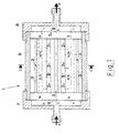
- Fig. 1 shows how the device is made up of one or more multi-pole bar magnets 2, four in the figure, which are composed of permanent magnets of a known type with a magnetic induction of between 2000 and 12,000 gauss.
- said bars 2 which are arranged parallel and equidistant, are composed of two contiguous bipolar magnetic segments 2a, 2b, 2c, which are lined up and face one another with alternating like-directed polarities N-N or S-S, as indicated in the figure; the permanent magnetic fields that are concatenated to said segments increase in intensity moving from one end of multi-pole bar magnet 2 to the other (toward the right in Figs. 1 and 3).
- Bars 2 which have a circular section in the example shown, can also have sections in the shape of polygons or other forms. It is beneficial for centers 0 of the straight segments of bar magnets 2 to rest on circumferences that are perpendicular to longitudinal axes h-h of bar magnets 2 themselves.
- each of said multi-pole bar magnets 2 parallel to each of said multi-pole bar magnets 2 are arranged one or more flux-carrying bars 3, 3e that are made of a ferromagnetic material and have a section as desired (circular in the figures).
- one bar 3 of said bars is arranged between each pair of multi-pole bar magnets 2, equidistant from the latter, and another flux-carrying bar 3e, which also has a circular section, is then arranged with its longitudinal axis K-K passing through said centers E of circumferences (a) on which rest centers 0 of the straight segments of multi-pole bar magnets 2.
- the fuel as it moves along its path (indicated by arrows A), is abruptly subjected to the action of very high and increasing magnetic induction, causing the molecules of the fuel, which have already been spread out, to become magnetically polarized.
- each of multi-pole bar magnets 2 ends in the faces of two bipolar segments that have opposite polarizations, thus effectively closing the magnetic circuit. This is equivalent to saying that bipolar segments 2a, 2b, 2c that each make up multi-pole bar magnet 2 have to be add in number (three in the case depicted).
- both flux-carrying bars 3, 3e and multi-pole bar magnets 2 are equal in length, and their ends are lined up with one another, such that it is possible to assemble from them all of said bars 2, 3, 3e using simple connectors 5 made of a non-magnetic material, e.g., copper, that are able to fit into said ends.
- a non-magnetic material e.g., copper
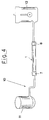
- a casing made of ferromagnetic material 6 thus contains in its interior said assembly of bars 2, 3, 3e and is equipped with non-magnetic connections 7, 8 to secure it to a tube of supply circuit 10 by known methods and as shown in Fig. 4, where the device is inserted between pump 11 and the intake manifold of an internal-combustion engine 12.
- the lubricating oil which should absorb very small amounts of uncombusted waste particles, has a very long service life, longer than its maximum lubricating capacity.
Landscapes
- Engineering & Computer Science (AREA)
- Chemical & Material Sciences (AREA)
- Chemical Kinetics & Catalysis (AREA)
- Combustion & Propulsion (AREA)
- Mechanical Engineering (AREA)
- General Engineering & Computer Science (AREA)
- Feeding And Controlling Fuel (AREA)
- Production Of Liquid Hydrocarbon Mixture For Refining Petroleum (AREA)
- Polarising Elements (AREA)
Claims (4)
- Dispositif à polarisation magnétique(1) pour un circuit d'alimentation en carburant (10) de brûleurs ou de moteurs à combustion interne, comprenant des aimants parallèles multi-pôles (2) en forme de barres logés à l'intérieur d'un carter (6) qui forme intérieurement des passages (9) à travers lesquels ledit carburant peut s'écouler, dans lequel chacun desdits aimants multi-pôles (2) en forme de barre est constitué d'un nombre impair de segments magnétiques bipolaires continus (2a, 2b, 2c) alignés axialement, se faisant face les uns les autres avec des polarités magnétiques dirigées de façon analogue, et ayant ainsi des polarités de directions opposées correspondant aux extrémités de chaque barre (2), caractérisé en ce que lesdits segments magnétiques ont des champs magnétiques liés d'intensité croissante, ainsi qu'en ce que, entre chaque paire d'aimants multi-pôles (2) en forme de barres et à même distance de ces derniers, est disposée une barre de transport de flux (3,3e) parallèle en un matériau ferromagnétique, de façon à produire plusieurs lignes de flux qui traversent, avec un flux croissant le long de chaque barre (3,3e), des zones (9) que traverse le carburant à traiter.
- Dispositif selon la revendication 1, dans lequel les aimants multi-pôles parallèles (2) en forme de barres sont équidistants et sont disposés avec les centres (O) de leurs segments rectilignes qui reposent sur des circonférences (a) perpendiculaires à leurs axes longitudinaux (h-h), les dites barres de transport de flux (3,3e) étant parallèles aux aimants multi-pôles (2) en forme de barres eux-mêmes et étant de longueurs égales pour l'essentiel à celles de ces dernières.
- Dispositif selon la revendication 2, dans lequel l'une au moins (3e) des barres de transport de flux (3,3e) est disposée de façon que son axe longitudinal (K-K) passe par les centres (E) des circonférences sur lesquelles reposent les centres (O) des segments rectilignes des aimants multi-pôles (2) en forme de barres, avec les barres de transport de flux (3) restantes qui sont disposées le long de leurs circonférences (a) et qui sont équidistantes et à une distance prédéterminée des aimants multi-pôles (2) en forme de barres eux-mêmes.
- Dispositif selon la revendication 3, dans lequel les extrémités des aimants multi-pôles (2) en forme de barres et de leurs barres de transport de flux (3,3e) sont reliées par un dispositif de liaison (5) en un matériau non magnétique.
Priority Applications (1)
| Application Number | Priority Date | Filing Date | Title |
|---|---|---|---|
| ES96900005T ES2151651T3 (es) | 1996-01-04 | 1996-01-04 | Dispositivo de polarizacion magnetica para el tratamiento de combustibles. |
Applications Claiming Priority (1)
| Application Number | Priority Date | Filing Date | Title |
|---|---|---|---|
| PCT/IB1996/000005 WO1997025528A1 (fr) | 1996-01-04 | 1996-01-04 | Dispositif a polarisation magnetique destine au traitement du carburant |
Publications (2)
| Publication Number | Publication Date |
|---|---|
| EP0871820A1 EP0871820A1 (fr) | 1998-10-21 |
| EP0871820B1 true EP0871820B1 (fr) | 2000-11-15 |
Family
ID=11004399
Family Applications (1)
| Application Number | Title | Priority Date | Filing Date |
|---|---|---|---|
| EP96900005A Expired - Lifetime EP0871820B1 (fr) | 1996-01-04 | 1996-01-04 | Dispositif a polarisation magnetique destine au traitement du carburant |
Country Status (7)
| Country | Link |
|---|---|
| US (1) | US6000382A (fr) |
| EP (1) | EP0871820B1 (fr) |
| AT (1) | ATE197631T1 (fr) |
| AU (1) | AU4272096A (fr) |
| DE (1) | DE69610994T2 (fr) |
| IL (1) | IL117227A (fr) |
| WO (1) | WO1997025528A1 (fr) |
Families Citing this family (15)
| Publication number | Priority date | Publication date | Assignee | Title |
|---|---|---|---|---|
| JP3019795B2 (ja) * | 1997-01-06 | 2000-03-13 | 株式会社ビッグバン | 磁気を用いたエンジン用燃焼改善装置 |
| AUPQ762900A0 (en) * | 2000-05-19 | 2000-06-15 | Muller, Jeffrey Alan | Device for saving fuel and reducing emissions |
| DE10106532A1 (de) * | 2001-02-13 | 2002-08-29 | Matthias Herberich | Vorrichtung zur Aufbereitung von Kraftstoffen |
| ITCR20010004A1 (it) * | 2001-06-08 | 2002-12-08 | Crete Trading Srl | Rocedimento di riscaldamento e doppia polarizzazione elettromagneticaper combuatibili liquidi e gassosi e relativo dispositivo |
| NO316089B1 (no) * | 2002-03-15 | 2003-12-08 | Magnetic Emission Control As | Magnetisk forbehandling av luft til en forbrenningsmotor |
| US7574997B1 (en) * | 2002-10-16 | 2009-08-18 | Chauza Roger N | Mobile engine performance demonstration unit |
| CN100453624C (zh) * | 2003-04-23 | 2009-01-21 | 王文浩 | 纳米颗粒燃料油及其制备方法 |
| US7004153B2 (en) * | 2003-06-13 | 2006-02-28 | Wout Lisseveld | Fuel treatment device using a magnetic field |
| HU227097B1 (hu) * | 2004-11-03 | 2010-07-28 | Tamas Szalai | Mágneses kezelõegység folyékony és légnemû anyagokhoz |
| CN101146990B (zh) * | 2005-03-21 | 2010-05-26 | 罗斯·詹姆士·特纳 | 连续添加锡到燃料中的装置以及提高内燃机性能的方法 |
| EP1775456A1 (fr) * | 2005-10-13 | 2007-04-18 | Eco-PowerStar GmbH | Procédé et dispositif pour l'activation de combustibles liquides ou gaseux en particulier de carburant essence et diesel, kérosène, gasoil, gaz naturel ou similaire |
| US8444853B2 (en) * | 2010-02-22 | 2013-05-21 | Lev Nikolaevich Popov | Leo-polarizer for treating a fluid flow by magnetic field |
| US8366927B2 (en) | 2010-07-19 | 2013-02-05 | Combustive Control Systems Ccs Corporation | Device for altering molecular bonds in fluids |
| GB201220561D0 (en) * | 2012-11-15 | 2013-01-02 | Spencer Robert J | Magnetic treatment of fluids |
| US20180106223A1 (en) * | 2016-10-13 | 2018-04-19 | Eduardas Ceremis | System and Method for Improving Fuel Mileage of Internal Combustion Engine |
Family Cites Families (9)
| Publication number | Priority date | Publication date | Assignee | Title |
|---|---|---|---|---|
| US3680705A (en) * | 1970-02-25 | 1972-08-01 | George M Happ | Magnetic structure for treating liquids containing calcareous matter |
| US4201140A (en) * | 1979-04-30 | 1980-05-06 | Robinson T Garrett | Device for increasing efficiency of fuel |
| US4357237A (en) * | 1979-11-28 | 1982-11-02 | Sanderson Charles H | Device for the magnetic treatment of water and liquid and gaseous fuels |
| US4414951A (en) * | 1981-02-02 | 1983-11-15 | Frank Saneto | Vehicle fuel conditioning apparatus |
| JP2525999B2 (ja) * | 1992-08-11 | 1996-08-21 | 株式会社アールエッチ企画 | 燃料磁界処理装置 |
| ES1026351U (es) * | 1993-11-22 | 1994-04-16 | Torre Barreiro De | Economizador de combustible. |
| JPH07217507A (ja) * | 1994-02-02 | 1995-08-15 | Miyazaki Hiroyuki | 給送燃料油改質装置 |
| US5716520A (en) * | 1995-08-30 | 1998-02-10 | Mason; Elmer B. | Magnetic fluid conditioner |
| US5816226A (en) * | 1997-07-09 | 1998-10-06 | Jernigan; Carl L. | In-line fuel treatment device |
-
1996
- 1996-01-04 US US09/101,161 patent/US6000382A/en not_active Expired - Fee Related
- 1996-01-04 AT AT96900005T patent/ATE197631T1/de not_active IP Right Cessation
- 1996-01-04 EP EP96900005A patent/EP0871820B1/fr not_active Expired - Lifetime
- 1996-01-04 DE DE69610994T patent/DE69610994T2/de not_active Expired - Fee Related
- 1996-01-04 WO PCT/IB1996/000005 patent/WO1997025528A1/fr not_active Ceased
- 1996-01-04 AU AU42720/96A patent/AU4272096A/en not_active Abandoned
- 1996-02-22 IL IL11722796A patent/IL117227A/en not_active IP Right Cessation
Also Published As
| Publication number | Publication date |
|---|---|
| DE69610994T2 (de) | 2001-03-15 |
| IL117227A0 (en) | 1996-06-18 |
| ATE197631T1 (de) | 2000-12-15 |
| IL117227A (en) | 2001-05-20 |
| AU4272096A (en) | 1997-08-01 |
| US6000382A (en) | 1999-12-14 |
| WO1997025528A1 (fr) | 1997-07-17 |
| EP0871820A1 (fr) | 1998-10-21 |
| DE69610994D1 (de) | 2000-12-21 |
Similar Documents
| Publication | Publication Date | Title |
|---|---|---|
| US6000382A (en) | Magnetic polarization device for treating fuel | |
| US5664546A (en) | Fuel saving device | |
| US5882514A (en) | Apparatus for magnetically treating fluids | |
| US5076246A (en) | Device for conditioning of liquid fuel and liquid coolant | |
| CA2229534C (fr) | Traitement par un fluide magnetique | |
| EP0544395A2 (fr) | Dispositif pour le traitement magnétique de liquides, gaz ou solides | |
| EP0473133B1 (fr) | Dispositif magnétique pour le traitement du combustible | |
| JP2002538369A (ja) | 優れた熱伝達特性を有する先端加熱型燃料噴射器 | |
| CN100416074C (zh) | 用于实现节油及减少排放的装置 | |
| CN201080871Y (zh) | 多极磁化燃油节油器 | |
| CA2094066A1 (fr) | Appareil destine au traitement magnetique du carburant | |
| Raut et al. | Experimental inspection by using the effect of magnetic field on the performance of diesel engine | |
| EP2218898A1 (fr) | Dispositif pour économiser du carburant | |
| SU1388573A1 (ru) | Устройство дл магнитной обработки жидкости | |
| WO1995004000A1 (fr) | Dispositif et procede servant a ameliorer la combustion d'un carburant | |
| RU2115010C1 (ru) | Устройство для магнитной обработки жидкости | |
| WO2001015801A1 (fr) | Dispositif de traitement de fluide | |
| EP0465705A1 (fr) | Dispositif de conditionnement de carburant liquide et de réfrigérant liquide | |
| KR20060098484A (ko) | 연료절감기 | |
| KR200228302Y1 (ko) | 액체연료활성화장치 | |
| KR101024570B1 (ko) | 매연저감장치 | |
| CN2158923Y (zh) | 强磁耐高温节油器 | |
| KR20000002237A (ko) | 연료절감기 | |
| KR19980028902U (ko) | 엔진의 연료 미립자 장치 | |
| KR960003129B1 (ko) | 매연 감소기 |
Legal Events
| Date | Code | Title | Description |
|---|---|---|---|
| PUAI | Public reference made under article 153(3) epc to a published international application that has entered the european phase |
Free format text: ORIGINAL CODE: 0009012 |
|
| 17P | Request for examination filed |
Effective date: 19980708 |
|
| AK | Designated contracting states |
Kind code of ref document: A1 Designated state(s): AT BE DE ES FR GB IT SE |
|
| GRAG | Despatch of communication of intention to grant |
Free format text: ORIGINAL CODE: EPIDOS AGRA |
|
| 17Q | First examination report despatched |
Effective date: 19991217 |
|
| GRAG | Despatch of communication of intention to grant |
Free format text: ORIGINAL CODE: EPIDOS AGRA |
|
| GRAH | Despatch of communication of intention to grant a patent |
Free format text: ORIGINAL CODE: EPIDOS IGRA |
|
| GRAH | Despatch of communication of intention to grant a patent |
Free format text: ORIGINAL CODE: EPIDOS IGRA |
|
| GRAA | (expected) grant |
Free format text: ORIGINAL CODE: 0009210 |
|
| AK | Designated contracting states |
Kind code of ref document: B1 Designated state(s): AT BE DE ES FR GB IT SE |
|
| PG25 | Lapsed in a contracting state [announced via postgrant information from national office to epo] |
Ref country code: IT Free format text: LAPSE BECAUSE OF FAILURE TO SUBMIT A TRANSLATION OF THE DESCRIPTION OR TO PAY THE FEE WITHIN THE PRE;WARNING: LAPSES OF ITALIAN PATENTS WITH EFFECTIVE DATE BEFORE 2007 MAY HAVE OCCURRED AT ANY TIME BEFORE 2007. THE CORRECT EFFECTIVE DATE MAY BE DIFFERENT FROM THE ONE RECORDED.SCRIBED TIME-LIMIT Effective date: 20001115 Ref country code: BE Free format text: LAPSE BECAUSE OF FAILURE TO SUBMIT A TRANSLATION OF THE DESCRIPTION OR TO PAY THE FEE WITHIN THE PRESCRIBED TIME-LIMIT Effective date: 20001115 Ref country code: AT Free format text: LAPSE BECAUSE OF FAILURE TO SUBMIT A TRANSLATION OF THE DESCRIPTION OR TO PAY THE FEE WITHIN THE PRESCRIBED TIME-LIMIT Effective date: 20001115 |
|
| REF | Corresponds to: |
Ref document number: 197631 Country of ref document: AT Date of ref document: 20001215 Kind code of ref document: T |
|
| ET | Fr: translation filed | ||
| REF | Corresponds to: |
Ref document number: 69610994 Country of ref document: DE Date of ref document: 20001221 |
|
| REG | Reference to a national code |
Ref country code: ES Ref legal event code: FG2A Ref document number: 2151651 Country of ref document: ES Kind code of ref document: T3 |
|
| PG25 | Lapsed in a contracting state [announced via postgrant information from national office to epo] |
Ref country code: SE Free format text: LAPSE BECAUSE OF FAILURE TO SUBMIT A TRANSLATION OF THE DESCRIPTION OR TO PAY THE FEE WITHIN THE PRESCRIBED TIME-LIMIT Effective date: 20010215 |
|
| PLBE | No opposition filed within time limit |
Free format text: ORIGINAL CODE: 0009261 |
|
| STAA | Information on the status of an ep patent application or granted ep patent |
Free format text: STATUS: NO OPPOSITION FILED WITHIN TIME LIMIT |
|
| 26N | No opposition filed | ||
| REG | Reference to a national code |
Ref country code: GB Ref legal event code: IF02 |
|
| PGFP | Annual fee paid to national office [announced via postgrant information from national office to epo] |
Ref country code: FR Payment date: 20060126 Year of fee payment: 11 |
|
| PGFP | Annual fee paid to national office [announced via postgrant information from national office to epo] |
Ref country code: ES Payment date: 20070126 Year of fee payment: 12 |
|
| PGFP | Annual fee paid to national office [announced via postgrant information from national office to epo] |
Ref country code: GB Payment date: 20070131 Year of fee payment: 12 |
|
| PGFP | Annual fee paid to national office [announced via postgrant information from national office to epo] |
Ref country code: DE Payment date: 20070201 Year of fee payment: 12 |
|
| GBPC | Gb: european patent ceased through non-payment of renewal fee |
Effective date: 20080104 |
|
| PG25 | Lapsed in a contracting state [announced via postgrant information from national office to epo] |
Ref country code: DE Free format text: LAPSE BECAUSE OF NON-PAYMENT OF DUE FEES Effective date: 20080801 |
|
| REG | Reference to a national code |
Ref country code: FR Ref legal event code: ST Effective date: 20081029 |
|
| PG25 | Lapsed in a contracting state [announced via postgrant information from national office to epo] |
Ref country code: GB Free format text: LAPSE BECAUSE OF NON-PAYMENT OF DUE FEES Effective date: 20080104 |
|
| REG | Reference to a national code |
Ref country code: ES Ref legal event code: FD2A Effective date: 20080105 |
|
| PG25 | Lapsed in a contracting state [announced via postgrant information from national office to epo] |
Ref country code: FR Free format text: LAPSE BECAUSE OF NON-PAYMENT OF DUE FEES Effective date: 20080131 |
|
| PG25 | Lapsed in a contracting state [announced via postgrant information from national office to epo] |
Ref country code: FR Free format text: LAPSE BECAUSE OF NON-PAYMENT OF DUE FEES Effective date: 20070131 |
|
| PG25 | Lapsed in a contracting state [announced via postgrant information from national office to epo] |
Ref country code: ES Free format text: LAPSE BECAUSE OF NON-PAYMENT OF DUE FEES Effective date: 20080105 |