EP0871847B1 - Kodierer/dekodierer zur überwachung einer infusionspumpe - Google Patents
Kodierer/dekodierer zur überwachung einer infusionspumpe Download PDFInfo
- Publication number
- EP0871847B1 EP0871847B1 EP97932268A EP97932268A EP0871847B1 EP 0871847 B1 EP0871847 B1 EP 0871847B1 EP 97932268 A EP97932268 A EP 97932268A EP 97932268 A EP97932268 A EP 97932268A EP 0871847 B1 EP0871847 B1 EP 0871847B1
- Authority
- EP
- European Patent Office
- Prior art keywords
- blocking area
- state
- detector
- encoder wheel
- motor shaft
- Prior art date
- Legal status (The legal status is an assumption and is not a legal conclusion. Google has not performed a legal analysis and makes no representation as to the accuracy of the status listed.)
- Revoked
Links
- 238000001802 infusion Methods 0.000 title claims abstract description 27
- 238000012544 monitoring process Methods 0.000 title claims abstract description 13
- 230000007704 transition Effects 0.000 claims abstract description 28
- 238000000034 method Methods 0.000 claims abstract description 13
- 230000003287 optical effect Effects 0.000 claims description 31
- 230000000903 blocking effect Effects 0.000 claims 23
- 238000001514 detection method Methods 0.000 claims 4
- 230000008859 change Effects 0.000 description 9
- 238000013461 design Methods 0.000 description 7
- 239000012530 fluid Substances 0.000 description 6
- 230000000694 effects Effects 0.000 description 5
- 238000005086 pumping Methods 0.000 description 4
- 238000011144 upstream manufacturing Methods 0.000 description 4
- 230000002159 abnormal effect Effects 0.000 description 3
- 230000003213 activating effect Effects 0.000 description 3
- 230000008901 benefit Effects 0.000 description 3
- 230000006870 function Effects 0.000 description 2
- 238000001990 intravenous administration Methods 0.000 description 2
- 102100021943 C-C motif chemokine 2 Human genes 0.000 description 1
- WQZGKKKJIJFFOK-GASJEMHNSA-N Glucose Natural products OC[C@H]1OC(O)[C@H](O)[C@@H](O)[C@@H]1O WQZGKKKJIJFFOK-GASJEMHNSA-N 0.000 description 1
- 101000897480 Homo sapiens C-C motif chemokine 2 Proteins 0.000 description 1
- FAPWRFPIFSIZLT-UHFFFAOYSA-M Sodium chloride Chemical compound [Na+].[Cl-] FAPWRFPIFSIZLT-UHFFFAOYSA-M 0.000 description 1
- WQZGKKKJIJFFOK-VFUOTHLCSA-N beta-D-glucose Chemical compound OC[C@H]1O[C@@H](O)[C@H](O)[C@@H](O)[C@@H]1O WQZGKKKJIJFFOK-VFUOTHLCSA-N 0.000 description 1
- 150000001875 compounds Chemical class 0.000 description 1
- 238000012937 correction Methods 0.000 description 1
- 238000013479 data entry Methods 0.000 description 1
- 239000003792 electrolyte Substances 0.000 description 1
- 239000011521 glass Substances 0.000 description 1
- 239000008103 glucose Substances 0.000 description 1
- 230000005484 gravity Effects 0.000 description 1
- 239000004973 liquid crystal related substance Substances 0.000 description 1
- 230000002572 peristaltic effect Effects 0.000 description 1
- 230000010363 phase shift Effects 0.000 description 1
- 239000004800 polyvinyl chloride Substances 0.000 description 1
- 230000008569 process Effects 0.000 description 1
- 238000012545 processing Methods 0.000 description 1
- 230000009467 reduction Effects 0.000 description 1
- 230000001105 regulatory effect Effects 0.000 description 1
- 239000004065 semiconductor Substances 0.000 description 1
- 239000011780 sodium chloride Substances 0.000 description 1
- 238000012546 transfer Methods 0.000 description 1
Images




Classifications
-
- G—PHYSICS
- G01—MEASURING; TESTING
- G01D—MEASURING NOT SPECIALLY ADAPTED FOR A SPECIFIC VARIABLE; ARRANGEMENTS FOR MEASURING TWO OR MORE VARIABLES NOT COVERED IN A SINGLE OTHER SUBCLASS; TARIFF METERING APPARATUS; MEASURING OR TESTING NOT OTHERWISE PROVIDED FOR
- G01D5/00—Mechanical means for transferring the output of a sensing member; Means for converting the output of a sensing member to another variable where the form or nature of the sensing member does not constrain the means for converting; Transducers not specially adapted for a specific variable
- G01D5/12—Mechanical means for transferring the output of a sensing member; Means for converting the output of a sensing member to another variable where the form or nature of the sensing member does not constrain the means for converting; Transducers not specially adapted for a specific variable using electric or magnetic means
- G01D5/244—Mechanical means for transferring the output of a sensing member; Means for converting the output of a sensing member to another variable where the form or nature of the sensing member does not constrain the means for converting; Transducers not specially adapted for a specific variable using electric or magnetic means influencing characteristics of pulses or pulse trains; generating pulses or pulse trains
- G01D5/245—Mechanical means for transferring the output of a sensing member; Means for converting the output of a sensing member to another variable where the form or nature of the sensing member does not constrain the means for converting; Transducers not specially adapted for a specific variable using electric or magnetic means influencing characteristics of pulses or pulse trains; generating pulses or pulse trains using a variable number of pulses in a train
- G01D5/2451—Incremental encoders
-
- G—PHYSICS
- G01—MEASURING; TESTING
- G01D—MEASURING NOT SPECIALLY ADAPTED FOR A SPECIFIC VARIABLE; ARRANGEMENTS FOR MEASURING TWO OR MORE VARIABLES NOT COVERED IN A SINGLE OTHER SUBCLASS; TARIFF METERING APPARATUS; MEASURING OR TESTING NOT OTHERWISE PROVIDED FOR
- G01D5/00—Mechanical means for transferring the output of a sensing member; Means for converting the output of a sensing member to another variable where the form or nature of the sensing member does not constrain the means for converting; Transducers not specially adapted for a specific variable
- G01D5/12—Mechanical means for transferring the output of a sensing member; Means for converting the output of a sensing member to another variable where the form or nature of the sensing member does not constrain the means for converting; Transducers not specially adapted for a specific variable using electric or magnetic means
- G01D5/244—Mechanical means for transferring the output of a sensing member; Means for converting the output of a sensing member to another variable where the form or nature of the sensing member does not constrain the means for converting; Transducers not specially adapted for a specific variable using electric or magnetic means influencing characteristics of pulses or pulse trains; generating pulses or pulse trains
- G01D5/245—Mechanical means for transferring the output of a sensing member; Means for converting the output of a sensing member to another variable where the form or nature of the sensing member does not constrain the means for converting; Transducers not specially adapted for a specific variable using electric or magnetic means influencing characteristics of pulses or pulse trains; generating pulses or pulse trains using a variable number of pulses in a train
Definitions
- the present invention relates to positional encoder/decoders for monitoring the position of motor shafts in medical infusion pumps.
- intravenous medical fluids to a patient
- a solution such as saline, glucose or electrolyte contained in a glass or flexible container
- a conduit such as a polyvinyl chloride (PVC) intravenous (TV) tube
- PVC polyvinyl chloride
- TV intravenous
- the fluid is infused under the forces of gravity, and the rate of flow is controlled by a roller clamp which is adjusted to restrict the flow lumen of the IV tube until the desired flow rate is obtained.
- Flow from the container to the patient also is known to be regulated by means other than a roller clamp. It is becoming more and more common to use an electronically controlled infusion pump.
- infusion pumps include, for example, peristaltic-type pumps and valve-type pumps.
- Valve-type pumps employ pumping chambers and upstream and downstream valves to sequentially impart the propulsion to the fluid.
- Peristaltic-type pumps typically include an array of cams angularly spaced from each other which drive cam followers connected to pressure fingers. These elements cooperate to impart linear wave motion on the pressure fingers. This linear wave motion is used to apply force to the IV tube, which imparts the motion to the fluid in the IV tube, thereby propelling the fluid.
- An alternative type of peristaltic pump employs a plurality of roller members which roll over the IV tube to impart the motion to the fluid in the IV tube.
- Such infusion pumps include various motors. Examples of such motors include driving motors which drive the pumping hardware and tube loading motors which drive tube loading hardware. Such driving motors can be variable speed motors.
- infusion pumps in the art have the potential for mechanical effects on the rotation of the motor during the pumping period.
- mechanical effects can be caused by, for example, temperature variations, variable battery power, motor friction, tubing variances and peak torque requirements.
- Such mechanical effects can be solved by adjusting power supplied to the motor to compensate for the torque variation.
- Another area in which accurate monitoring is important is in monitoring the direction and rotation of the motor. Pump motors can move in an abnormal direction as a result of, for example, improper application of the driving signal. When such abnormal operation occurs, it is desirable to signal such abnormal operation so correction can be made.
- Such electromechanical position encoder/decoders generally comprise a quadrature shaft encoder whose two outputs sense the presence or absence of an idicia or a flag to indicate motor shaft positional information relative to some starting point.
- Use of two channels generating quadrature signals allows the direction as well as the distance moved to be monitored and is further known in the art.
- the resolution of the monitoring information is determined by the number of flags on the encoder wheel.
- a decoder such as an up-down counter preceded by an appropriate state decoding circuit is used to process the signals from the encoder.
- the state decoding logic samples the input signals at a rate which ensures that, at the maximum signal frequency, consecutive states are guaranteed to be sampled.
- the up-down counter output provides positional information relative to the starting position.
- Such motor shaft encoder/decoders of the prior art suffer from several drawbacks.
- the input signals are asynchronous to the decoder clock, and if the state decoder logic samples the input signals at the signal edge, the decoder may enter a metastable state which is indeterminate and may result in incorrect updating of position. While the likelihood of metastability occurring can be reduced to acceptable levels by appropriate digital design techniques known in the art, implementation of these techniques increases the cost of such systems.
- a motor shaft encoder/decoder which avoids the issue of metastability during state transitions of the signals from a quadrature shaft encoder.
- the encoder/decoder also should effectively gather rotational directional information. Additionally, such a device should avoid use of a separate counter or clock. The device should provide these benefits in a cost efficient and effective design.
- the present invention provides an encoder/decoder which effectively gathers rotational directional information.
- the present invention obviates the necessity for separate circuit for counting state transitions of the encoder/decoder.
- the present invention provides these benefits with an efficient, cost effective design.
- the present invention achieves these advantages by utilizing a state transition of a first sensor to initiate a sample of a constant signal from a second sensor corresponding to the center of a flag or sector, which acts to block light.
- an infusion pump in which the present invention can be utilized is referred to generally as 10.
- the infusion pump 10 can be clamped onto a standard IV pole 12.
- the infusion pump 10 includes a main body portion 14 and at least one pump module portion 16. In the embodiment depicted and described herein, two pump module portions 16 are provided.
- the main body 14 further includes a liquid crystal display (LCD) area 23 which is used to convey various information about the infusion pump 10 to the user and provide for user interface with the infusion pump 10.
- the main body 14 includes data-entry keys 25.
- the pump module 16 includes a tube-loading channel 27 and an vacuum fluorescent display area 29.
- the tube loading channel 27 utilizes an automatic tube loader described below.
- the main body portion 14 includes a slave microprocessor which is a slave to a master microprocessor.
- the master microprocessor is a 80C186 EB available from Intel Corporation, Santa Clara, California
- the slave microprocessor is a 80C552 available from Phillips Semiconductors, Sunnyvale, California.
- the pump modules 16 further include a pump module microprocessor.
- the pump module microprocessor is a 68 HC11 available from Motorola, Schaumburg, Illinois.
- the pump module microprocessor includes software in read-only memory (ROM) which drives the monitoring functions described below
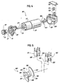
- the tubeloader sub-assembly is mounted on two shafts. These two shafts are the tubeloader camshaft 32 and the tubeloader layshaft 34.
- the tubeloader layshaft 34 provides an axis about which parts driven by camshaft 32 rotate. Moving upstream along layshaft 34, the most outboard of the elements associated therewith are the downstream tubeloader pawls 36.
- the downstream tubeloader pawls 36 each consist of an annular body 38 which is adapted to ride fixed on the tubeloader layshaft 34.
- the pawl arm 40 Extending forward of the pawl annulus 38 is the pawl arm 40.
- the pawl arm 40 has a substantially linear section 42 and an arctuate section 44 extending outwardly and downward from the pawl collet 38.
- the pawl tip 46 encompasses a plurality of areas.
- the interior side of the pawl tip 46 defines a horizontal tube engaging surface 48, an angled tube engaging surface 50, a vertical tube capture surface 52, and a horizontal tube misload activating surface 54.
- the exterior side of the pawl tip 46 defines an externally facing tube rejection surface 55. These surfaces operate in concert with a downstream platen (not shown).
- the shape of the arctuate section 44 of the pawl 36 is such that when the pawl 36 is fully lowered, the tube is firmly wedged against the downstream platen.
- the design and the function comprehended by tubeloader pawl tip 46 is repeated on the lower edge of an upper pump jaw 57.
- the tubeloader pawl tips 46 are lowered over the tube in the tube loading channel 27 which, in combination with the lowering of the upper jaw 57, serves to completely close off the tube loading channel 27 on the outboard side of the infusion pump 10. Should a tube be partially inserted into the infusion pump 10, yet remain wholly outside the tube loading channel 27, the tube reject surface 55 will operate to help expel the tube from the infusion pump 10. In the event a tube is loaded partially within the tube loading channel 27, the misload activating surface 54 will help to pinch the tube.
- the tube capture surface 52 will serve to draw the tube rearwardly and thereby execute a correct loading of the tube.
- the combination of the tube reject surface 44, the misload activating surface 54 and the tube capture surface 52 provides for a sharp discontinuity between the various loading scenarios.
- the vertical tube capture surface 52 additionally works in combination with the angled tube engaging surface 50 and the horizontal tube engaging surface 48 to hold the tube securely in the infusion pump 10. This combination also helps provide for a deformation of the tube by co-action of the angled surface 50 and the horizontal surface 48 to lock the tube securely into the infusion pump 10.
- two helical gears 59, 61 are provided in a perpendicular arrangement so as to transfer rotation from a tubeloader motor 63 to the transverse tubeloader camshaft 32.
- the tubeloader motor 63 is a motor.
- the tubeloader motor 63 further comprises a speed reduction gearset 65 operative to provide sufficient torque to rotate camshaft 32 against the drag placed thereon by the components in contact therewith and resident on layshaft 34.
- a tubeloader motor shaft 67 extends forwardly from the tubeloader motor 63 and passes through the tubeloader motor mount 69 by way of a central aperture 71.
- the tubeloader motor shaft 67 has a flat 73 defined therein which is operative to provide a seat for the tubeloader drive gear setscrew 75 which is inserted through a threaded setscrew aperture 77 in the tubeloader drive gear 59 and thereby fix the rotation of the tubeloader drive gear 59 to that of the tubeloader motor shaft 67.
- the tubeloader drive gear 59 is a helical cut gear wherein the teeth are about the circumferential periphery thereof. These teeth engage corresponding teeth on the face of the tubeloader camshaft gear 61, thereby allowing perpendicular actuation of the transversely mounted camshaft 32 by the longitudinally mounted tubeloader motor 63.
- a handwheel 79 is provided which includes a housing for a pivoting clutch tab 80. In operation, actuation of the clutch tab 80 will cause the camshaft 32 to be freely rotated manually by means of handwheel 79 without rotating the camshaft gear 61.
- the camshaft 32 supports two compound cams denoted as the downstream cam 82 and the upstream cam 84.
- the downstream and upstream cams 82, 84 comprise, moving outwardly from chassis, a camshaft deadstop 86, 88, which help to provide a positive stop for camshaft rotation, tubeloader pawl cams 90, 92, which serve to actuate the tubeloader pawls 36, valve loading cams 94, 96, which serve to lift valves out of the way during the loading operation, and sensor arm cams 98, 100 which is operative to raise or lower the downstream sensor.
- the encoder assembly 101 comprises an encoder wheel 103 which is attached to the armature shaft 105 of motor 63.
- the encoder assembly 101 resides in a pump motor encoder support collar 107 which provides a sliding fit over motor housing 63 and is affixed thereto by a pinch clamp 109.
- Two optical couplers 111, 113 are provided which are electrically connected to the associated signal processing electronics by a printed circuit strip denoted as the pump sensor strip 115.
- the encoder wheel 103 has, in the described embodiment of the instant invention, two flags 117 extending radially outwardly from the hub 121 thereof. Located between each flags are a plurality of equispace sectors 119. While in the embodiment described herein each sector 119 is 90° wide, the present invention contemplates use of encoder wheels having any number of sectors and thus any width. Likewise while in the embodiment described herein each flag 119 between each sector 119 is 90° wide, the present invention contemplates use of encoder wheels having any number of flags and thus any width.
- the sectors 119 act to pass light while the flags 117 act to block light.
- Blocked light can be assigned a digital logic high or 1 reference while passed light can be assigned a digital logic low or 0 reference.
- These flags present a plurality of optical images. The first of these images is defined by the edge 118 of the individual flag 117. The second image is defined by the central area of the flag 117.
- the flags 117 act in concert with the two optical couplers 111, 113 to fix the location of the armature shaft 105 of the pump motor 63.
- the spacing of the two optical couplers 111, 113 is provided to obtain the desired quadrature signals with the signals nominally 90° out of phase.
- the optical couplers 111, 113 are positioned such that when one is aligned with the edge of a flag 118, the other optical coupler is aligned with the center of a flag 120.
- the optical couplers are either 45° or 135° apart. If four flags and four sectors were employed, the optical couplers would be 22 1/2°, 67 1/2°, 112 1/2° or 157 1/2° apart to achieve the nominal 90° phase shift.
- the optical couplers 111, 113 comprise a photo-electric switch.
- the photo electric switches comprise a first photo diode 123 and a first photocell 125.
- the optical couplers 111, 113 are oriented to correspond with the plurality of flags 117 on the encoder wheel 103 thus acting to optically read the flags 117 and sectors 119.
- the timing of the readings taken by optical couplers 111, 113 may be controlled by the pump module microprocessor or may be initiated by changes in the readings themselves.
- the optical readings of optical couplers are converted to digital signals by means of squaring circuits and input into a digital processor contained in the microprocessor.
- the resolution of encoder 103 is 1/960 of a rotation of tubeloader camshaft 32.
- the exact configuration of the present embodiment can be readily altered while maintaining the desired effect of the present device.
- the optical couplers can be moved to an equivalent position which still provides the desired effect.
- encoder wheels having any number of flags and sectors are contemplated as within the scope of the present invention.
- the present device can be coordinated with the use of different types of driving motors such as the driving motor of the pumping motion. Of course, these various configurations are contemplated within the scope of the present invention.
- the waveform of a conventional encoder/decoder comprises two channels (A, B) wherein each channel has a first digital logic high state and a second digital logic low state.
- the state definition correspond to four distinct states.
- the first state defined as State 0
- both channels (A, B) are at a digital logic low (e.g. A , B ).
- state 1 the first channel (A) is at a digital logic high while the second channel (B) is at a digital logic low (e.g. A, B ).
- the state transition from state 0 to state I occurs when the first optical coupler 111 detects the transition from a sector 119 to a flag 117.
- the first channel (A) is at a digital logic high and the second channel (B) is at a digital logic high (e.g. A, B).
- the transition from state 1 to state 2 occurs when the second optical coupler 113 detects the transition from a sector 119 to a flag 117.
- the first channel (A) is at a digital logic low while the second channel (B) is at a digital logic high (e.g. A , B).
- the state transition from state 2 to state 3 occurs when the first optical coupler 111 detects the transition from a flag 117 to a sector 119.
- state 3 the state definition returns to state 0, with both channels (A, B) at a digital logic low (e.g. A , B ).
- the state transition from state 3 to state 0 occurs when the second optical coupler 113 detects the transition from a flag 117 to a sector 119. Subsequent state transitions repeat this pattern.
- This conventional design necessitates use of a clock state machine such as a decoder counter to keep successive counts in an internal register.
- a typical decoder counter which was utilized in conventional designs was a Hewlett Packard HTCL 2000.
- the decoder counter includes means to address the metastability states which may occur within the decoder counter internal logic during state transitions.
- two state waveforms (A', B') provide two encoder outputs.
- the state determination is self-clocking.
- a state change in one of the waveforms (A', B') is registered as an interrupt or internal control signal in the microprocessor. Rather than using an external clock or register, the associated software recognizes each interrupt and causes a state change in the microprocessor itself.
- state 0 is defined when the second optional coupler 113 detects the transition from a flag 117 to a sector 119 or vice versa and the first optical coupler 111 detects the midpoint of a sector 119.
- State 1 is defined when the first optical coupler 111 detects a transition from a sector 119 to a flag 117 or vice versa and the second optical coupler 113 detects the mid point of a sector 119.
- State 2 is defined when the second optical coupler 113 detects a transition from a sector 119 to a flag 117 or vice versa and the first optical coupler 111 detects the midpoint of a flag 117.
- State 3 is defined when the first optical coupler 111 detects a transition from a flag 117 to a sector 119 or vice versa and the second optical coupler 113 detects the midpoint of a flag 117. After state 3, the state definition returns to state 0. This arises when the second optical coupler 113 detects a transition from a flag 117 to a sector 119 and the first optical coupler 111 detects the midpoint of a sector 119.
- the present invention avoids the metastability issue without the use of expensive hardware.
- the present invention retains the ability of the encoder/decoder to derive rotational directional information.
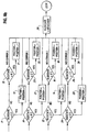
- the optical sensors sense changes in the A' or B' waveforms. This occurs if the optical sensor detects a transition from a flag 117 to a sector 119 or a sector 119 to a flag 117. If a change is sensed in the A' waveform, at step 1, the B waveform is sampled in step 3. If a change is not sensed on the A' waveform, at step 1, the B' waveform is sensed, at step 2. If a change is sensed in the B' waveform, at step 2, the A' waveform is sampled at step 4.
- the method includes three variables: the newstate variable, the oldstate variable and the position variable. If at step 5 the B' waveform is at a digital high, at step 7 newstate is defined as three (3). If at step 5 the B' waveform is at a digital low, at step 9 newstate is defined as one (1). If at step 6 the A' waveform is at a digital high, at step 8 newstate is defined as two (2). If at step 6 the A' waveform is at a digital low, at step 10 newstate is defined as zero (0).
- oldstate is read at step 11. If oldstate is two (2), at step 13 the position variable is incremented by one, and the oldstate variable is set to the newstate variable value of three (3), at step 28. After setting the oldstate variable, the loop continues. If oldstate at step 11 is not two (2), then oldstate is again tested at step 15. If at step 15 oldstate is zero (0), then at step 17 the position variable is decremented by one, and the oldstate variable is reset to the newstate variable value of three (3), at step 28. After setting the oldstate variable, the loop continues. If at step 15 oldstate is not zero (0), a state change in the waveform has been missed or the waveform has been misread and an error condition occurs.
- oldstate is tested at step 19. If oldstate is zero (0), at step 21 the position variable is incremented by one, and the oldstate variable is set to the newstate variable value of zero (0), at step 28. After setting the oldstate variable, the loop continues. If oldstate at step 19 is not zero (0), then oldstate is again tested at step 23. If at step 23 oldstate is two (2), then at step 25 the position variable is decremented by one, and the oldstate variable is reset to the newstate variable value of zero (0), at step 28. After setting the oldstate variable, the loop continues. If at step 23 oldstate is not two (2), a state change in the waveform has been missed or the waveform has been misread and an error condition occurs.
- oldstate is tested at step 12. If oldstate is one (1), at step 14 the position variable is incremented by one, and the oldstate variable is set to the newstate variable value of two (2), at step 28. After setting the oldstate variable, the loop continues. If oldstate at step 12 is not one (1), then oldstate is again tested at step 16. If at step 16 oldstate is three (3), then at step 18 the position variable is decremented by one, and the oldstate variable is set to the newstate variable value of two (2), at step 28. After setting the oldstate variable, the loop continues. If at step 16 oldstate is not three (3), a state change in the waveform has been missed or the waveform has been misread and an error condition is designated.
- oldstate is tested at step 20. If oldstate is three (3), at step 22 the position variable is incremented by one, and the oldstate variable is set to the newstate variable value of zero (0), at step 28. After setting the oldstate variable, the loop continues. If oldstate at step 20 is not three (3), then oldstate is again tested at step 24. If at step 24 oldstate is one (1), then at step 26 the position variable is decremented by one, and the oldstate variable is set to the newstate variable value of zero (0), at step 28. After setting the oldstate variable, the loop continues. If at step 24 oldstate is not one (1), a state change in the waveform has been missed or the waveform has been misread and an error condition is designated.
Landscapes
- Physics & Mathematics (AREA)
- General Physics & Mathematics (AREA)
- Infusion, Injection, And Reservoir Apparatuses (AREA)
- External Artificial Organs (AREA)
- Medicines Containing Antibodies Or Antigens For Use As Internal Diagnostic Agents (AREA)
Claims (13)
- Monitor zum Überwachen der Position einer Motorwelle, der folgendes aufweist:ein Codierrad, das mit der Motorwelle verbindbar ist, wobei das Codierrad mindestens einen Blockierbereich und mindestens einen Nichtblockierbereich definiert;einen ersten Detektor zum Detektieren der Anwesenheit oder Abwesenheit des Blockierbereichs des Codierrades;einen zweiten Detektor, der in bezug auf den ersten Detektor versetzt ist, zum Detektieren der Anwesenheit oder Abwesenheit des Blockierbereichs des Codierrades;eine Einrichtung zum Korrelieren der Position der Motorwelle mit einem von einer Vielzahl von Zuständen, die durch die Ablesewerte des ersten und des zweiten Detektors definiert sind; undeine Einrichtung innerhalb der Korreliereinrichtung für den Übergang von einem Zustand in einen anderen Zustand, wenn von dem einen Detektor ein Übergang zwischen einem Blockierbereich und einem Nichtblockierbereich detektiert wird, und zum Bestimmen des Zustands durch die von dem zweiten Detektor detektierte Anwesenheit oder Abwesenheit des Blockierbereichs, wenn der Übergang von dem ersten Detektor detektiert wird.
- Verfahren zum Überwachen der Position einer Motorwelle, das die folgenden Schritte aufweist:Definieren von mindestens einem Blockierbereich und mindestens einem Nichtblockierbereich eines Codierrades, das mit der Motorwelle verbunden ist;Detektieren der Anwesenheit oder Abwesenheit des Blockierbereichs des Codierrades;Detektieren, an einer zweiten Stelle, der Anwesenheit oder Abwesenheit des Blockierbereichs des Codierrades;Korrelieren der Position der Motorwelle mit einem von einer Vielzahl von Zuständen, die durch die Ablesewerte des ersten und desr zweiten Detektiervorgangs definiert werden; undDurchführen eines Überganges von einem Zustand in einen anderen Zustand, wenn durch einen Detektiervorgang ein Übergang zwischen einem Blockierbereich und einem Nichtblockierbereich detektiert wird, und Bestimmen des Zustands durch die durch den zweiten Detektiervorgang detektierte Anwesenheit oder Abwesenheit des Blockierbereichs, wenn der Übergang durch den ersten Detektiervorgang detektiert wird.
- Verfahren nach Anspruch 2,
das ferner die Schritte des Definierens von mindestens zwei Zuständen aufweist. - Verfahren nach Anspruch 3,
das ferner die Schritte des Definierens von mindestens vier Zuständen aufweist. - Monitor zum Überwachen der Position einer Motorwelle, der folgendes aufweist:ein Codierrad, das an die Motorwelle anschließbar ist, wobei das Codierrad mindestens einen Blockierbereich und mindestens einen Nichtblockierbereich aufweist;einen ersten Detektor, der die Anwesenheit oder Abwesenheit des Blockierbereichs des Codierrades detektiert;einen zweiten Detektor, der in bezug auf den ersten Detektor versetzt ist und die Anwesenheit oder Abwesenheit des Blockierbereichs des Codierrades detektiert;eine Korreliereinrichtung, die die Position der Motorwelle mit einem von einer Vielzahl von Zuständen korreliert, die durch die Ablesewerte des ersten und des zweiten Detektors definiert sind; undwobei die Korreliereinrichtung folgendes aufweist: eine Übergangseinrichtung, die einen Übergang von einem Zustand in einen anderen Zustand vornimmt, wenn von dem einen Detektor ein Übergang zwischen einem Blockierbereich und einem Nichtblockierbereich detektiert wird, und eine Bestimmungseinrichtung, die den Zustand durch die von dem zweiten Detektor detektierte Anwesenheit oder Abwesenheit des Blockierbereichs bestimmt, wenn der Übergang von dem ersten Detektor detektiert wird.
- Monitor nach Anspruch 1 oder 5,
wobei das Codierrad eine Vielzahl von Blockierbereichen und Nichtblockierbereichen aufweist. - Monitor nach Anspruch 1 oder 5,
wobei die Detektoren Optokoppler sind. - Monitor nach Anspruch 7,
wobei der Optokoppler eine Fotodiode und eine Fotozelle aufweist. - Monitor nach Anspruch 1 oder 5,
wobei mindestens zwei Zustände definiert sind. - Monitor nach Anspruch 1 oder 5,
wobei vier Zustände definiert sind. - Monitor nach Anspruch 1 oder 5,
wobei die Korreliereinrichtung ein Mikroprozessor ist. - Monitor nach Anspruch 1 oder 5,
wobei das Codierrad an eine Motorwelle In einer Infusionspumpe anschließbar ist. - Monitor nach Anspruch 12,
wobei ferner die Motorwelle mit einem Schlauchlademotor verbunden ist.
Applications Claiming Priority (3)
| Application Number | Priority Date | Filing Date | Title |
|---|---|---|---|
| GB9622434 | 1996-10-29 | ||
| GB9622434A GB2319079B (en) | 1996-10-29 | 1996-10-29 | Infusion pump monitoring encoder/decoder |
| PCT/US1997/010978 WO1998019135A1 (en) | 1996-10-29 | 1997-06-24 | Infusion pump monitoring encoder/decoder |
Publications (2)
| Publication Number | Publication Date |
|---|---|
| EP0871847A1 EP0871847A1 (de) | 1998-10-21 |
| EP0871847B1 true EP0871847B1 (de) | 2003-08-27 |
Family
ID=10802073
Family Applications (1)
| Application Number | Title | Priority Date | Filing Date |
|---|---|---|---|
| EP97932268A Revoked EP0871847B1 (de) | 1996-10-29 | 1997-06-24 | Kodierer/dekodierer zur überwachung einer infusionspumpe |
Country Status (11)
| Country | Link |
|---|---|
| US (1) | US6078273A (de) |
| EP (1) | EP0871847B1 (de) |
| JP (1) | JP2000506614A (de) |
| KR (1) | KR19990076874A (de) |
| AT (1) | ATE248351T1 (de) |
| DE (1) | DE69724407T2 (de) |
| DK (1) | DK0871847T3 (de) |
| ES (1) | ES2206735T3 (de) |
| GB (1) | GB2319079B (de) |
| TW (1) | TW355139B (de) |
| WO (1) | WO1998019135A1 (de) |
Cited By (1)
| Publication number | Priority date | Publication date | Assignee | Title |
|---|---|---|---|---|
| CN106014945A (zh) * | 2016-05-30 | 2016-10-12 | 创世科研有限公司 | 一种微型水泵出水量的精确控制方法及微型水泵 |
Families Citing this family (17)
| Publication number | Priority date | Publication date | Assignee | Title |
|---|---|---|---|---|
| US7287398B2 (en) * | 2001-09-25 | 2007-10-30 | Alsius Corporation | Heating/cooling system for indwelling heat exchange catheter |
| US7645258B2 (en) * | 1999-12-01 | 2010-01-12 | B. Braun Medical, Inc. | Patient medication IV delivery pump with wireless communication to a hospital information management system |
| US6519569B1 (en) * | 1999-12-01 | 2003-02-11 | B. Braun Medical, Inc. | Security infusion pump with bar code reader |
| US6790198B1 (en) | 1999-12-01 | 2004-09-14 | B-Braun Medical, Inc. | Patient medication IV delivery pump with wireless communication to a hospital information management system |
| US7553295B2 (en) | 2002-06-17 | 2009-06-30 | Iradimed Corporation | Liquid infusion apparatus |
| US20030236489A1 (en) | 2002-06-21 | 2003-12-25 | Baxter International, Inc. | Method and apparatus for closed-loop flow control system |
| US6717302B2 (en) * | 2002-07-31 | 2004-04-06 | Danaher Controls Corporation | Motor for use with a sensor |
| US20090266840A1 (en) * | 2005-11-15 | 2009-10-29 | Foam In Place Co., Ltd. | Substance Injecting Apparatuses and Methods for Using Same |
| US20100137802A1 (en) * | 2007-05-11 | 2010-06-03 | Ofer Yodfat | Methods and appratus for monitoring rotation of an infusion pump driving mechanism |
| US8105282B2 (en) | 2007-07-13 | 2012-01-31 | Iradimed Corporation | System and method for communication with an infusion device |
| US8105269B2 (en) | 2008-10-24 | 2012-01-31 | Baxter International Inc. | In situ tubing measurements for infusion pumps |
| US8137083B2 (en) | 2009-03-11 | 2012-03-20 | Baxter International Inc. | Infusion pump actuators, system and method for controlling medical fluid flowrate |
| US8382447B2 (en) | 2009-12-31 | 2013-02-26 | Baxter International, Inc. | Shuttle pump with controlled geometry |
| US8567235B2 (en) | 2010-06-29 | 2013-10-29 | Baxter International Inc. | Tube measurement technique using linear actuator and pressure sensor |
| CN104582752B (zh) * | 2012-09-27 | 2018-05-04 | 泰尔茂株式会社 | 输液泵 |
| US11268506B2 (en) | 2017-12-22 | 2022-03-08 | Iradimed Corporation | Fluid pumps for use in MRI environment |
| US12505907B2 (en) * | 2022-11-23 | 2025-12-23 | Cerner Innovation, Inc. | Systems and methods for infusion pump formulary validation |
Family Cites Families (14)
| Publication number | Priority date | Publication date | Assignee | Title |
|---|---|---|---|---|
| US4869646A (en) * | 1984-10-15 | 1989-09-26 | American Hospital Supply Corp. | Continuous peristaltic pump |
| JPS6392281A (ja) * | 1986-10-06 | 1988-04-22 | Sharp Corp | 補助磁場位置決め装置 |
| GB2228842B (en) * | 1989-01-09 | 1993-01-06 | Schlumberger Ind Ltd | Relative position transducer |
| US5279556A (en) * | 1989-04-28 | 1994-01-18 | Sharp Kabushiki Kaisha | Peristaltic pump with rotary encoder |
| DE3921756C1 (de) * | 1989-07-01 | 1991-01-03 | Teldix Gmbh, 6900 Heidelberg, De | |
| EP0441963A4 (en) * | 1989-07-07 | 1991-11-21 | Kabushiki Kaisha Yaskawa Denki Seisakusho | Absolute value encoder |
| US5130710A (en) * | 1989-10-18 | 1992-07-14 | Pitney Bowes Inc. | Microcomputer-controlled electronic postage meter having print wheels set by separate D.C. motors |
| US5003239A (en) * | 1990-01-11 | 1991-03-26 | Baxter International Inc. | Peristaltic pump monitoring device |
| US5444613A (en) * | 1990-07-30 | 1995-08-22 | Teac Corporation | Device for generating a signal representative of the position of an angularly or linearly moveable member |
| JPH04333904A (ja) * | 1991-05-09 | 1992-11-20 | Brother Ind Ltd | サーボモータの制御装置 |
| US5438330A (en) * | 1991-10-28 | 1995-08-01 | Nikon Corporation | Absolute encoder |
| JP2500386B2 (ja) * | 1991-11-15 | 1996-05-29 | 株式会社精工舎 | デジタル表示値調整装置 |
| US5482438A (en) * | 1994-03-09 | 1996-01-09 | Anderson; Robert L. | Magnetic detent and position detector for fluid pump motor |
| US5534691A (en) * | 1994-09-12 | 1996-07-09 | Ivac Corporation | System for determining pumping mechanism position while limiting volume of fluid pumped |
-
1996
- 1996-10-29 GB GB9622434A patent/GB2319079B/en not_active Expired - Fee Related
-
1997
- 1997-01-22 US US08/786,276 patent/US6078273A/en not_active Expired - Fee Related
- 1997-06-24 EP EP97932268A patent/EP0871847B1/de not_active Revoked
- 1997-06-24 AT AT97932268T patent/ATE248351T1/de not_active IP Right Cessation
- 1997-06-24 ES ES97932268T patent/ES2206735T3/es not_active Expired - Lifetime
- 1997-06-24 KR KR1019980705001A patent/KR19990076874A/ko not_active Ceased
- 1997-06-24 JP JP10520431A patent/JP2000506614A/ja not_active Ceased
- 1997-06-24 DK DK97932268T patent/DK0871847T3/da active
- 1997-06-24 DE DE69724407T patent/DE69724407T2/de not_active Expired - Fee Related
- 1997-06-24 WO PCT/US1997/010978 patent/WO1998019135A1/en not_active Ceased
- 1997-07-05 TW TW086109492A patent/TW355139B/zh active
Cited By (1)
| Publication number | Priority date | Publication date | Assignee | Title |
|---|---|---|---|---|
| CN106014945A (zh) * | 2016-05-30 | 2016-10-12 | 创世科研有限公司 | 一种微型水泵出水量的精确控制方法及微型水泵 |
Also Published As
| Publication number | Publication date |
|---|---|
| GB9622434D0 (en) | 1997-01-08 |
| KR19990076874A (ko) | 1999-10-25 |
| ES2206735T3 (es) | 2004-05-16 |
| EP0871847A1 (de) | 1998-10-21 |
| ATE248351T1 (de) | 2003-09-15 |
| GB2319079B (en) | 2000-07-12 |
| DE69724407T2 (de) | 2004-06-24 |
| DK0871847T3 (da) | 2003-12-22 |
| WO1998019135A1 (en) | 1998-05-07 |
| WO1998019135A8 (en) | 1999-12-02 |
| JP2000506614A (ja) | 2000-05-30 |
| US6078273A (en) | 2000-06-20 |
| TW355139B (en) | 1999-04-01 |
| DE69724407D1 (de) | 2003-10-02 |
| GB2319079A (en) | 1998-05-13 |
Similar Documents
| Publication | Publication Date | Title |
|---|---|---|
| EP0871847B1 (de) | Kodierer/dekodierer zur überwachung einer infusionspumpe | |
| JP3399961B2 (ja) | 生物医学装置における電動機の位置を決定するシステム | |
| JP4511388B2 (ja) | 容量注入ポンプ | |
| GB2338759A (en) | Infusion pump valve with rounded vertex | |
| EP0462238B1 (de) | Vorrichtung zur Überwachung der Rotation einer Antriebswelle insbesondere in einer peristaltischen Pumpe | |
| CA2404845A1 (en) | Volumetric infusion pump |
Legal Events
| Date | Code | Title | Description |
|---|---|---|---|
| PUAI | Public reference made under article 153(3) epc to a published international application that has entered the european phase |
Free format text: ORIGINAL CODE: 0009012 |
|
| 17P | Request for examination filed |
Effective date: 19980612 |
|
| AK | Designated contracting states |
Kind code of ref document: A1 Designated state(s): AT BE CH DE DK ES FR IE IT LI NL SE |
|
| GRAH | Despatch of communication of intention to grant a patent |
Free format text: ORIGINAL CODE: EPIDOS IGRA |
|
| GRAH | Despatch of communication of intention to grant a patent |
Free format text: ORIGINAL CODE: EPIDOS IGRA |
|
| GRAA | (expected) grant |
Free format text: ORIGINAL CODE: 0009210 |
|
| AK | Designated contracting states |
Designated state(s): AT BE CH DE DK ES FR IE IT LI NL SE |
|
| REG | Reference to a national code |
Ref country code: CH Ref legal event code: EP |
|
| REG | Reference to a national code |
Ref country code: CH Ref legal event code: NV Representative=s name: KEMENY AG PATENTANWALTBUERO |
|
| REG | Reference to a national code |
Ref country code: IE Ref legal event code: FG4D |
|
| REF | Corresponds to: |
Ref document number: 69724407 Country of ref document: DE Date of ref document: 20031002 Kind code of ref document: P |
|
| REG | Reference to a national code |
Ref country code: SE Ref legal event code: TRGR |
|
| REG | Reference to a national code |
Ref country code: DK Ref legal event code: T3 |
|
| REG | Reference to a national code |
Ref country code: ES Ref legal event code: FG2A Ref document number: 2206735 Country of ref document: ES Kind code of ref document: T3 |
|
| ET | Fr: translation filed | ||
| PLBI | Opposition filed |
Free format text: ORIGINAL CODE: 0009260 |
|
| PG25 | Lapsed in a contracting state [announced via postgrant information from national office to epo] |
Ref country code: IE Free format text: LAPSE BECAUSE OF NON-PAYMENT OF DUE FEES Effective date: 20040624 Ref country code: AT Free format text: LAPSE BECAUSE OF NON-PAYMENT OF DUE FEES Effective date: 20040624 |
|
| PG25 | Lapsed in a contracting state [announced via postgrant information from national office to epo] |
Ref country code: SE Free format text: LAPSE BECAUSE OF NON-PAYMENT OF DUE FEES Effective date: 20040625 Ref country code: ES Free format text: LAPSE BECAUSE OF NON-PAYMENT OF DUE FEES Effective date: 20040625 |
|
| PLAX | Notice of opposition and request to file observation + time limit sent |
Free format text: ORIGINAL CODE: EPIDOSNOBS2 |
|
| PG25 | Lapsed in a contracting state [announced via postgrant information from national office to epo] |
Ref country code: LI Free format text: LAPSE BECAUSE OF NON-PAYMENT OF DUE FEES Effective date: 20040630 Ref country code: DK Free format text: LAPSE BECAUSE OF NON-PAYMENT OF DUE FEES Effective date: 20040630 Ref country code: CH Free format text: LAPSE BECAUSE OF NON-PAYMENT OF DUE FEES Effective date: 20040630 Ref country code: BE Free format text: LAPSE BECAUSE OF NON-PAYMENT OF DUE FEES Effective date: 20040630 |
|
| 26 | Opposition filed |
Opponent name: DR. JOHANNES HEIDENHAIN GMBH Effective date: 20040521 |
|
| NLR1 | Nl: opposition has been filed with the epo |
Opponent name: DR. JOHANNES HEIDENHAIN GMBH |
|
| PLAX | Notice of opposition and request to file observation + time limit sent |
Free format text: ORIGINAL CODE: EPIDOSNOBS2 |
|
| PLBB | Reply of patent proprietor to notice(s) of opposition received |
Free format text: ORIGINAL CODE: EPIDOSNOBS3 |
|
| BERE | Be: lapsed |
Owner name: *BAXTER INTERNATIONAL INC. Effective date: 20040630 |
|
| PG25 | Lapsed in a contracting state [announced via postgrant information from national office to epo] |
Ref country code: NL Free format text: LAPSE BECAUSE OF NON-PAYMENT OF DUE FEES Effective date: 20050101 Ref country code: DE Free format text: LAPSE BECAUSE OF NON-PAYMENT OF DUE FEES Effective date: 20050101 |
|
| REG | Reference to a national code |
Ref country code: DK Ref legal event code: EBP |
|
| EUG | Se: european patent has lapsed | ||
| EUG | Se: european patent has lapsed | ||
| REG | Reference to a national code |
Ref country code: CH Ref legal event code: PL |
|
| PG25 | Lapsed in a contracting state [announced via postgrant information from national office to epo] |
Ref country code: FR Free format text: LAPSE BECAUSE OF NON-PAYMENT OF DUE FEES Effective date: 20050228 |
|
| NLV4 | Nl: lapsed or anulled due to non-payment of the annual fee |
Effective date: 20050101 |
|
| REG | Reference to a national code |
Ref country code: IE Ref legal event code: MM4A |
|
| REG | Reference to a national code |
Ref country code: FR Ref legal event code: ST |
|
| RDAF | Communication despatched that patent is revoked |
Free format text: ORIGINAL CODE: EPIDOSNREV1 |
|
| PG25 | Lapsed in a contracting state [announced via postgrant information from national office to epo] |
Ref country code: IT Free format text: LAPSE BECAUSE OF NON-PAYMENT OF DUE FEES Effective date: 20050624 |
|
| REG | Reference to a national code |
Ref country code: ES Ref legal event code: FD2A Effective date: 20040625 |
|
| RDAG | Patent revoked |
Free format text: ORIGINAL CODE: 0009271 |
|
| STAA | Information on the status of an ep patent application or granted ep patent |
Free format text: STATUS: PATENT REVOKED |
|
| 27W | Patent revoked |
Effective date: 20050703 |