EP0871945B1 - Afficheur destine a l'utilisation dans un systeme de securite magnetique contre le vol - Google Patents
Afficheur destine a l'utilisation dans un systeme de securite magnetique contre le vol Download PDFInfo
- Publication number
- EP0871945B1 EP0871945B1 EP96946049A EP96946049A EP0871945B1 EP 0871945 B1 EP0871945 B1 EP 0871945B1 EP 96946049 A EP96946049 A EP 96946049A EP 96946049 A EP96946049 A EP 96946049A EP 0871945 B1 EP0871945 B1 EP 0871945B1
- Authority
- EP
- European Patent Office
- Prior art keywords
- strip
- field
- bias
- change
- strip according
- Prior art date
- Legal status (The legal status is an assumption and is not a legal conclusion. Google has not performed a legal analysis and makes no representation as to the accuracy of the status listed.)
- Expired - Lifetime
Links
Images
Classifications
-
- G—PHYSICS
- G08—SIGNALLING
- G08B—SIGNALLING SYSTEMS, e.g. PERSONAL CALLING SYSTEMS; ORDER TELEGRAPHS; ALARM SYSTEMS
- G08B13/00—Burglar, theft or intruder alarms
- G08B13/22—Electrical actuation
- G08B13/24—Electrical actuation by interference with electromagnetic field distribution
- G08B13/2402—Electronic Article Surveillance [EAS], i.e. systems using tags for detecting removal of a tagged item from a secure area, e.g. tags for detecting shoplifting
- G08B13/2405—Electronic Article Surveillance [EAS], i.e. systems using tags for detecting removal of a tagged item from a secure area, e.g. tags for detecting shoplifting characterised by the tag technology used
- G08B13/2408—Electronic Article Surveillance [EAS], i.e. systems using tags for detecting removal of a tagged item from a secure area, e.g. tags for detecting shoplifting characterised by the tag technology used using ferromagnetic tags
-
- C—CHEMISTRY; METALLURGY
- C22—METALLURGY; FERROUS OR NON-FERROUS ALLOYS; TREATMENT OF ALLOYS OR NON-FERROUS METALS
- C22C—ALLOYS
- C22C45/00—Amorphous alloys
- C22C45/02—Amorphous alloys with iron as the major constituent
-
- G—PHYSICS
- G08—SIGNALLING
- G08B—SIGNALLING SYSTEMS, e.g. PERSONAL CALLING SYSTEMS; ORDER TELEGRAPHS; ALARM SYSTEMS
- G08B13/00—Burglar, theft or intruder alarms
- G08B13/22—Electrical actuation
- G08B13/24—Electrical actuation by interference with electromagnetic field distribution
- G08B13/2402—Electronic Article Surveillance [EAS], i.e. systems using tags for detecting removal of a tagged item from a secure area, e.g. tags for detecting shoplifting
- G08B13/2428—Tag details
- G08B13/2437—Tag layered structure, processes for making layered tags
- G08B13/2442—Tag materials and material properties thereof, e.g. magnetic material details
-
- H—ELECTRICITY
- H10—SEMICONDUCTOR DEVICES; ELECTRIC SOLID-STATE DEVICES NOT OTHERWISE PROVIDED FOR
- H10N—ELECTRIC SOLID-STATE DEVICES NOT OTHERWISE PROVIDED FOR
- H10N35/00—Magnetostrictive devices
- H10N35/80—Constructional details
- H10N35/85—Magnetostrictive active materials
Definitions
- the invention relates to a display element for use in a magnetic anti-theft system consisting of an elongated, ductile, magnetostrictive strip consisting of amorphous ferromagnetic material, which can be activated / deactivated by applying / removing a bias magnetic field H K and which is activated by an alternating magnetic field longitudinal, mechanical resonance vibrations can be excited at a resonance frequency f r , the mechanical stresses resulting from the resonance vibrations causing a change in the magnetization of the strip and thus a detectable change in the magnetization of the strip.
- This property causes such a streak preferably then stimulates mechanical vibrations, when exposed to a bias field, the Size a large change in length with the same change of Magnetic field. Furthermore, the effect of Magnetic field change in length that occurs in this area the length of the strip changes without any pulling force acts on the strip.
- the mechanical vibration of a strip is for the Resonance frequency of the vibration of the modulus of elasticity Material decisive.
- the material works as if it were less than the mechanical one would have modulus of elasticity.
- this is achieved, for example, by that one with the soft magnetic stripe connected semi-hard magnetic stripes demagnetized.
- the vibration can be prevented in the you switch off this bias field.
- the alloys proposed there are not very high Signal amplitude and no long stopping of the signal after Switch off the exciting field on its resonance frequency is strongly dependent on the bias field strength and their deactivation possibility is restricted, so that not a sufficiently large change in the resonance frequency when The bias field is removed.
- the object of the present invention is therefore to display elements to further develop the type mentioned at the beginning, that a high signal amplitude and a long one Stop the signal after switching off the exciting field there is a slight dependence of the resonance frequency on the pre-magnetic field strength is present at the same time the strip can be deactivated safely, i.e. a sufficiently large change in the resonance frequency when removing the premagnetizing field, as well as a sufficient ductility so that mechanical stress without affecting the magnetic properties is possible.
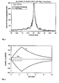
- the core of a display element is a ferromagnetic, magnetostrictive strip, which is marked by a magnetic Alternating field to longitudinal, mechanical resonance vibrations is excited. Due to the magnetostrictive coupling cause the mechanical associated with the vibration Voltages a change in magnetization which occurs in the receiver coil induces a corresponding voltage, so that Display element can be demonstrated.
- Figure 1 illustrates the resonant increase of the induced voltage as Function of the frequency of the exciting alternating field.
- the signal typically lasts for a few milliseconds.
- figure 2 gives a schematic illustration. This is one more or less unique feature and reduces possible false alarms by e.g. Shopping carts and other magnetic items to an absolute minimum. Because the stimulating magnetic field a voltage is also induced in the receiver coils also clear that the sensitivity of the system is increased if this background noise disappears.
- the excitation takes place with alternating field pulses, the receiver side during the dead time between the pulses is active and tries to detect the display element.
- the main characteristic of a display element is the resonance frequency of the strip.
- Such resonance frequencies lie typically around the value of 60 kHz. That means that Excitation of the mechanical natural vibration and the associated resonant increase of the induced voltage only occurs if the stripe exactly the resonance frequency has.
- the modulus of elasticity depends on ferromagnetic materials and thus the resonance frequency also from the state of magnetization, i.e. of the strength of an externally magnetic direct field. This is of central importance Importance for the functioning of the system as well for the requirements of the magnetic material used.
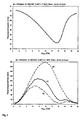
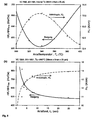
- Figure 3 gives an example of the typical course of the resonance frequency and the signal amplitude as a function of an external one biasing direct field.
- the label is deactivated by the semi-hard Strip is demagnetized, i.e. the premagnetizing Field is switched off. This results in an upset the resonance frequency and at the same time a clear one Decrease in the resonance amplitude.
- the magnetoelastic effects naturally require a magnetostrictive material.
- the magnetostrictive distortion ⁇ with respect to the ideal magnetized state is through given, where ⁇ s denotes the saturation magnetostriction and ⁇ the angle between the magnetization and the considered expansion axis.
- ⁇ s denotes the saturation magnetostriction
- ⁇ the angle between the magnetization and the considered expansion axis.
- a magnetostrictive change in length and thus a magnetic excitation of mechanical vibrations is only possible if the magnetization process takes place via turning processes.
- This calls for magnetic anisotropies that are difficult or oblique to the direction of magnetization.
- the latter naturally corresponds to an elongated strip strip due to the demagnetization effects of the longitudinal strip direction.
- the amorphous ferromagnetic alloy Fe 40 Ni 38 Mo 4 B 18 which is known from WO 90/03652, is used in the prior art.
- the disadvantage of this alloy is that it is not compatible with other anti-theft systems, these other anti-theft systems being based on the detection of harmonics.
- a magneto-elastic display element based on this alloy generates harmonics in the deactivated state with alternating field excitation and thus triggers a false alarm in the aforementioned security systems. The reason for this is the non-linearity of the BH loop, which ultimately results from the distribution of the manufacturing-related internal tensions.
- the tempering of a uniaxial induced anisotropy across to the longitudinal direction eliminates the above problems. To the One becomes by chance by heat treatment of the manufacturing process resulting from internal tensions largely relaxed and the strength of the anisotropy can by choosing the alloy composition and tempering parameters be controlled very closely.
- H K H A + NJ a / ⁇ 0 together from the anisotropy field H A induced by the heat treatment and the anisotropy contribution NJ a / ⁇ 0 of the demagnetizing factor N of the sample.
- the latter can be described in a very good approximation by that of a flat ellipsoid, the values for bandwidth b , tape thickness d and strip length l being used for the semiaxes. It then applies to 1 ⁇ b >> d where K and E denote the complete elliptical integrals of the first and second kind.
- the demagnetization factor thus results in an additional influence of the band geometry on the magnetoelastic properties, which up to now has apparently hardly been known or was practically not taken into account.
- the decay time ie the damping of the signal, is determined by the purely mechanical damping (phenomenologically described by the parameter 1 / ⁇ 0 ) of the vibration, and by eddy currents (described by the second term in G1. (4)). In the case of finite bias, the contribution of eddy current damping usually dominates, which means that the resonance amplitude is expressed by the second expression in G1. (5) approximates.
- the primary requirement for anti-theft systems is the avoidance of false alarms, ie the safe deactivation of the display element.
- the absolute minimum value of ⁇ f r and thus the condition that no false alarm is triggered by the deactivated display element is ⁇ f r > 1.2 kHz.
- the value 1.75 kHz has proven to be particularly good on average.
- the natural frequency of the pre-magnetized strip depends as little as possible on the strength of the pre-magnetizing direct field. Different orientations of the strip in the earth's magnetic field alone result in changes in the working field strength of ⁇ 0.5 Oe ( ⁇ A / m). In addition there are changes of the same order of magnitude due to material scattering of the pre-magnetizing semi-hard strip that is usually used. Due to the dependence of the resonance frequency on the size of the pre-magnetic direct field, this leads to changes in the natural frequency of the oscillating strip. If these changes are too large, the strip of the interrogation zone of the anti-theft system is no longer recognized correctly, since the resonance frequency is a typical characteristic of the strip.
- the change in the resonance frequency df r compared to the change in the bias field strength dHx must be below a certain limit value at the operating point. Accordingly, there is an upper limit of
- for the amount of frequency slope with the field (at H 6 Oe) ⁇ 800 Hz / Oe particularly suitable. This condition stands for a good alarm trigger rate of the activated display elements.
- ⁇ f r ultimately corresponds to a lower limit value for the slope
- (H 6 Oe ⁇ 800 Hz / Oe) reduced to the specification of the frequency slope alone.
- the aim of alloy optimization is now to: Find alloy composition, which at a given Band geometry after heat treatment in a magnetic field Resonance frequency increases by 600 Hz / Oe (at 6 Oe) having.
- the relevant influencing variables remain the saturation magnetostriction ⁇ s , the saturation magnetization J s and the anisotropy field H K.
- Both ⁇ s and J s are primarily determined by the alloy composition and are hardly influenced by the heat treatment.
- the anisotropy field H K is determined both by the alloy composition and the heat treatment, as well as by the strip dimensions. It is also the strongest influencing factor, since it affects the frequency slope with the third power.
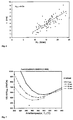
- FIG 8 gives an overview of the ultimate influence from composition and heat treatment to the Frequency slope, which is discussed in more detail below.
- the main influence in the heat treatment is the tempering time and the tempering temperature.
- the starting behavior of the Frequency slope can generally be as follows characterize:
- Tempering temperatures have proven best in this regard in the range of about 340 to 420 ° C and starting times of a few Seconds. For the reproducible implementation of this Short-term treatments are best suited to one fürlühung.
- the length of the annealing zone varies between approx. 20 cm and 2 m.
- the strength of the applied during the heat treatment Magnetic field is relatively irrelevant, as long as guaranteed is that it is high enough to make the material ferromagnetic to saturate.
- fields are sufficient depending on Band width and thickness of at least 100 Oe for a 6 mm wide and 25 ⁇ m thick band or 300 Oe for a 2 mm wide and 30 ⁇ m thick tape.
- Field strengths of 1 to 2 kOe are used.
- the tensile stress When tempering a tension-induced occurs under tension Anisotropy, the anisotropy of which depends on the composition or along the tension axis and thus the anisotropy field can easily strengthen or weaken. In practice the tensile stresses usually occur below 100 MPa your The cause lies in the mechanical friction between the belt and Tape guide. This is especially the case when the tape a transverse curvature annealed by appropriate guidance must become.
- the starting point was a variation in the Co contents and the metalloid contents.
- a balance of those caused by the reduction in cobalt Increase in the frequency slope by further reducing the Metalloid content is hardly possible.
- the reason is that it is a minimum content of silicon and boron of around 14 Atomic% is required for the tape to solidify amorphously.
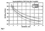
- the magnetoelastic properties are not only of the Composition, but also from the geometry of the Depending on the strip. Because the frequency-determining length more or less is given, this primarily affects the influence of bandwidth and in particular tape thickness.
- the value of the demagnetizing field is clearly smaller than the pure field-induced anisotropy, but it is large enough to cause a significant change in the entire anisotropy field H K.
- the dependence of the frequency slope on the bandwidth and the band thickness shown in FIG. 9 results accordingly.
- the strip thickness can range from 20 to 30 ⁇ m can be varied.
- the bandwidth must be smaller than that Resonator length and can be lowered to about 0.5 mm become.
- Table 1 below contains values for two different known alloys.
- the alloy under No. 1 and 2 is known from the already mentioned Wo 90/03652, while the alloy is mentioned under No. 3 in DE-GM 9412456.
- the tests relating to Nos. 1 and 2 were carried out on the same alloy. As example No. 1, the alloy was examined in the production state and under No.
- Example No. 1 has a change in the resonance frequency df r compared to the change in the bias field strength dH bias below 1 kHz, while the change in the resonance frequency with removal or with the addition of a bias field ⁇ fr has a change in the resonance frequency greater than 1.94.
- the signal height of 150 mV and the oscillation period are also sufficient for use in monitoring systems with mechanically oscillating labels.
- the alloy in No. 3 of Table 1 again shows how the one under number 1 a sufficiently low fluctuation the resonance frequency with respect to a change in the bias field strength, and also lies in the other values, Change in resonance frequency when the bias field is removed, Signal voltage and decay time, all in one usable area.
- the replacement of nickel with cobalt has but resulted in a cobalt content of 47.9 in the alloy is included, so that this alloy because of relatively high cobalt price for mass use offers economic disadvantages.
- the sample alloys were subjected to heat treatment in a transverse magnetic field to set the flat, linear loop.
- Typical tempering temperatures ranged from 280 to 440 ° C.
- the starting times ranged from a few seconds to several hours.
- the exact heat treatment requires a typical range of variation for the quantities ⁇ fr and
- the tests were carried out on strips with a length of 40 mm.
- the typical resonance frequencies were in the range of 50-60 kHz.
- Table 3 shows some compositions which do not achieve the object of the invention: No Composition (at%) Co (wt%)
- Nos. 28-33 have a significantly reduced Co content compared to the prior art (No. 3), but generally have a frequency spread
- No. 34 has a low frequency spread, but compared to the prior art (No. 3) this was only possible by increasing the Co content. Accordingly, the increased alloy costs are disadvantageous.
- Examples 35, 36 show compared to the prior art (No. 3) a lower Co content and a lower one Frequency spread on. However, the frequency change is after Demagnetization too small ( ⁇ 1 kHz). Another disadvantage is the small signal amplitude.
- the heat treatment for setting a flat loop is preferably done at a temperature of 250 to 450 ° C for a time of 2 to 60 seconds.
- the short treatment time allows the tape to pass through using a Continuous furnace heat-treated before winding into coils becomes. After the heat treatment in the continuous furnace the emerging belt can be immediately adjusted to the desired one Length for the surveillance strips can be cut to length.
- Typical dimensions of the strip for the intended If necessary, a length of 30 to 50 mm, a width from 0.5 to 25 mm and a thickness of the amorphous band in Range from 15 to 40 ⁇ m.
- the cooldown should be higher than 3 msec and the bias field is typically in the range of 400 to 800 A / m.
- advantageous Resonance frequencies are in the range from 50 to 60 kHz.
- the specified area initially only borders that in Alloys coming regardless of the specific Band geometry. It can be narrowed further if you Bandwidth and band thickness specified more precisely.
Landscapes
- Physics & Mathematics (AREA)
- Engineering & Computer Science (AREA)
- Electromagnetism (AREA)
- Automation & Control Theory (AREA)
- Computer Security & Cryptography (AREA)
- Chemical & Material Sciences (AREA)
- General Physics & Mathematics (AREA)
- Mechanical Engineering (AREA)
- Metallurgy (AREA)
- Organic Chemistry (AREA)
- Materials Engineering (AREA)
- Burglar Alarm Systems (AREA)
- Soft Magnetic Materials (AREA)
Claims (12)
- Bande ferromagnétique ductile, amorphe, pour un élément d'affichage dans un système anti-vol magnétique,tandis que le matériau ferromagnétique amorphe présente une boucle d'aimantation plate qui se développe le plus possible linéairement jusque dans le domaine de la saturation, et a une composition consistant en la formulequi est apte à être activée/désactivée par application/éloignement d'un champ de prémagnétisation Hbias et peut être excitée par un champ magnétique alternatif à l'état activé pour donner des oscillations de résonance mécaniques, longitudinales, à une fréquence de résonance Fr, tandis que les tensions mécaniques résultant des oscillations de résonance ont pour effet une modification de la magnétisation de la bande et induisent ainsi une variation détectable de la magnétisation de la bande, etqui présente une anisotropie magnétique transversalement à la direction longitudinale de la bande, tandis que l'intensité du champ d'anisotropie Hk est supérieure à l'intensité du champ de prémagnétisation Hbias, etqui subit, à l'état activé, pour une légère variation d'une intensité de champ de prémagnétisation d'essai Hbias = 6 Oe, une modification de la fréquence de résonance dfr par rapport à la modification de l'intensité du champ de prémagnétisation dHbias de 400 Hz/Oe < |dfr/dHbias| < 800 Hz/Oe et lors du passage de l'état activé à l'état désactivé subit une modification de la fréquence de résonance Δfr > 1,2 kHz,
7 ≤ b ≤ 23 10 ≤ e ≤ 20 5 ≤ c ≤ 50 0 ≤ f ≤ 2 0 ≤ d ≤ 10 0 ≤ g ≤ 3
et a + b + c + d + e + f + g = 100,
caractérisée par le fait que la bande dans l'état allongé ou dans l'état non allongé en forme de bande a été soumise à une température de 250°C ≤ T ≤ 450°C dans un champ magnétique approprié, transversalement à la direction de la bande, à un traitement thermique pour une durée de traitement thermique de 2 secondes ≤ t ≤ 60 secondes. - Bande selon la revendication 1,
caractérisée par le fait que le traitement thermique a été accompli en une passe et que la vitesse de passage a été choisie de telle manière que la bande a été chauffée pendant une durée de traitement thermique de 3 secondes ≤ t ≤ 10 secondes à une température de 350°C ≤ T ≤ 400°C dans un champ transversal ayant une intensité de champ B ≥ 800 Oe. - Bande selon la revendication 1 ou 2,
caractérisée par le fait que la bande présente une fréquence de résonance fr de 50 kHz ≤ fr ≤ 60 kHz. - Bande selon l'une des revendications 1 à 3,
caractérisée par le fait que la bande présente après réalisation d'une excitation par résonance une durée d'évanouissement τR ≥ 3 ms. - Bande selon l'une des revendications 1 à 4,
caractérisée par le fait que le matériau ferromagnétique amorphe présente une magnétostriction de saturation λS ≥ 15 ppm. - Bande selon l'une des revendications 1 à 5,
caractérisée par les conditions suivantes:0 ≤ d ≤ 5 7 ≤ b ≤ 20 13 ≤ e ≤ 18 28 ≤ c ≤ 38 0 ≤ f ≤ 1. - Bande selon l'une des revendications 1 à 6, caractérisée par la condition 8 ≤ [-0,463 b + 1,86 (d + g + (e + f)] ≤ 14.
- Bande selon l'une des revendications 1 à 7,
caractérisée par les conditions:30 ≤ c ≤ 36 14 ≤ e ≤ 17 0 ≤ d ≤ 2 0 ≤ f + g ≤ 1. - Bande selon l'une des revendications 1 à 8,
caractérisée par le fait que la bande a une longueur entre 25 mm et 50 mm, une largeur entre 1 mm et 15 mm et une épaisseur entre 15 µm et 30 µm. - Bande selon la revendication 9,
caractérisée par le fait que la bande présente une largeur d'environ 4 mm et consiste en Fe37,3 Co13 Ni34 Si1 B14,4 C0,4 ou Fe35,3 Co14,4 Ni34 Si1 B14,9 C0,4. - Bande selon la revendication 9,
caractérisée par le fait que la bande présente une largeur d'environ 6 mm et consiste en Fe37,5 Co15,3 Ni30 Si1,3 B15,5 C0,4 ou Fe36,7 Co13 Ni34 Si1 B14,9 C0,4. - Bande selon la revendication 9,
caractérisée par le fait que la bande présente une largeur d'environ 12 - 13 mm et consiste en Fe39,9 Co12,8 Ni30 Si1,5 B15,5 C0,3; Fe35,6 Co13 Ni34 Si1 B16 C0,4; ou Fe39,8-43,8 Co10 Ni30-34 Si1 B14,6 C0,4.
Applications Claiming Priority (3)
| Application Number | Priority Date | Filing Date | Title |
|---|---|---|---|
| DE19545755A DE19545755A1 (de) | 1995-12-07 | 1995-12-07 | Verwendung einer amorphen Legierung für magnetoelastisch anregbare Etiketten in auf mechanischer Resonanz basierenden Überwachungssystemen |
| DE19545755 | 1995-12-07 | ||
| PCT/DE1996/002342 WO1997021242A2 (fr) | 1995-12-07 | 1996-12-06 | Afficheur destine a l'utilisation dans un systeme de securite magnetique contre le vol |
Publications (2)
| Publication Number | Publication Date |
|---|---|
| EP0871945A2 EP0871945A2 (fr) | 1998-10-21 |
| EP0871945B1 true EP0871945B1 (fr) | 2004-04-21 |
Family
ID=7779509
Family Applications (1)
| Application Number | Title | Priority Date | Filing Date |
|---|---|---|---|
| EP96946049A Expired - Lifetime EP0871945B1 (fr) | 1995-12-07 | 1996-12-06 | Afficheur destine a l'utilisation dans un systeme de securite magnetique contre le vol |
Country Status (6)
| Country | Link |
|---|---|
| US (2) | US5728237A (fr) |
| EP (1) | EP0871945B1 (fr) |
| JP (1) | JPH09214015A (fr) |
| DE (2) | DE19545755A1 (fr) |
| ES (1) | ES2215202T3 (fr) |
| WO (1) | WO1997021242A2 (fr) |
Families Citing this family (14)
| Publication number | Priority date | Publication date | Assignee | Title |
|---|---|---|---|---|
| FR2746956B1 (fr) * | 1996-03-29 | 1998-05-07 | Soplaril Sa | Procede de mise en place d'au moins un fil ou une bande, generalement metallique, sur une feuille mince, machine pour la mise en oeuvre du procede, feuille comportant au moins un fil ou une bande, et bobine de cette feuille |
| DE19651525A1 (de) | 1996-12-11 | 1998-06-18 | Vacuumschmelze Gmbh | Etiketten in akustomagnetischen Diebstahlsicherungssystemen |
| US6057766A (en) * | 1997-02-14 | 2000-05-02 | Sensormatic Electronics Corporation | Iron-rich magnetostrictive element having optimized bias-field-dependent resonant frequency characteristic |
| US6018296A (en) * | 1997-07-09 | 2000-01-25 | Vacuumschmelze Gmbh | Amorphous magnetostrictive alloy with low cobalt content and method for annealing same |
| ZA983959B (en) * | 1997-08-25 | 1999-11-04 | Sensormatic Electronics Corp | Continuous process for transverse magnetic field annealing of amorphous material used in an eas marker and composition of amorphous material. |
| US6011475A (en) * | 1997-11-12 | 2000-01-04 | Vacuumschmelze Gmbh | Method of annealing amorphous ribbons and marker for electronic article surveillance |
| US6254695B1 (en) | 1998-08-13 | 2001-07-03 | Vacuumschmelze Gmbh | Method employing tension control and lower-cost alloy composition annealing amorphous alloys with shorter annealing time |
| US6359563B1 (en) * | 1999-02-10 | 2002-03-19 | Vacuumschmelze Gmbh | ‘Magneto-acoustic marker for electronic article surveillance having reduced size and high signal amplitude’ |
| JP4683803B2 (ja) * | 1999-07-09 | 2011-05-18 | 株式会社トスカ | セキュリティ糸及びその製法 |
| US6645314B1 (en) * | 2000-10-02 | 2003-11-11 | Vacuumschmelze Gmbh | Amorphous alloys for magneto-acoustic markers in electronic article surveillance having reduced, low or zero co-content and method of annealing the same |
| US7585459B2 (en) * | 2002-10-22 | 2009-09-08 | Höganäs Ab | Method of preparing iron-based components |
| DE102006047022B4 (de) | 2006-10-02 | 2009-04-02 | Vacuumschmelze Gmbh & Co. Kg | Anzeigeelement für ein magnetisches Diebstahlsicherungssystem sowie Verfahren zu dessen Herstellung |
| WO2010082195A1 (fr) | 2009-01-13 | 2010-07-22 | Vladimir Manov | Marqueurs magnétomécaniques et élément amorphe magnétostrictif destiné à être utilisé dans ce dernier |
| CN103577302A (zh) * | 2012-08-06 | 2014-02-12 | 鸿富锦精密工业(深圳)有限公司 | 电子设备及其监控方法 |
Family Cites Families (6)
| Publication number | Priority date | Publication date | Assignee | Title |
|---|---|---|---|---|
| US4510490A (en) * | 1982-04-29 | 1985-04-09 | Allied Corporation | Coded surveillance system having magnetomechanical marker |
| JPS60246604A (ja) * | 1984-05-22 | 1985-12-06 | Hitachi Metals Ltd | 巻磁心 |
| US4980670A (en) * | 1987-11-04 | 1990-12-25 | Sensormatic Electronics Corporation | Deactivatable E.A.S. marker having a step change in magnetic flux |
| DE68908184T2 (de) * | 1988-09-26 | 1993-11-25 | Allied Signal Inc | Glasartige metallegierung für mechanisch resonierende sicherungsmarkierungssysteme. |
| US5469140A (en) * | 1994-06-30 | 1995-11-21 | Sensormatic Electronics Corporation | Transverse magnetic field annealed amorphous magnetomechanical elements for use in electronic article surveillance system and method of making same |
| US5628840A (en) * | 1995-04-13 | 1997-05-13 | Alliedsignal Inc. | Metallic glass alloys for mechanically resonant marker surveillance systems |
-
1995
- 1995-12-07 DE DE19545755A patent/DE19545755A1/de not_active Withdrawn
-
1996
- 1996-12-04 JP JP8339005A patent/JPH09214015A/ja active Pending
- 1996-12-06 EP EP96946049A patent/EP0871945B1/fr not_active Expired - Lifetime
- 1996-12-06 ES ES96946049T patent/ES2215202T3/es not_active Expired - Lifetime
- 1996-12-06 WO PCT/DE1996/002342 patent/WO1997021242A2/fr not_active Ceased
- 1996-12-06 DE DE59610993T patent/DE59610993D1/de not_active Expired - Lifetime
- 1996-12-09 US US08/762,044 patent/US5728237A/en not_active Ceased
-
1998
- 1998-12-15 US US09/212,334 patent/USRE38098E1/en not_active Expired - Lifetime
Also Published As
| Publication number | Publication date |
|---|---|
| JPH09214015A (ja) | 1997-08-15 |
| USRE38098E1 (en) | 2003-04-29 |
| ES2215202T3 (es) | 2004-10-01 |
| WO1997021242A3 (fr) | 1997-08-07 |
| WO1997021242A2 (fr) | 1997-06-12 |
| DE19545755A1 (de) | 1997-06-12 |
| EP0871945A2 (fr) | 1998-10-21 |
| US5728237A (en) | 1998-03-17 |
| DE59610993D1 (de) | 2004-05-27 |
Similar Documents
| Publication | Publication Date | Title |
|---|---|---|
| DE69534931T2 (de) | Magnetomechanisches Markierungselement mit einem in Gegenwart eines transversalen magnetischen Feldes geglühten amorphen Teil zur Verwendung in einem elektronischen Artikelüberwachungssystem und Herstellungsverfahren dafür | |
| DE60015933T2 (de) | Magneto-akustischer marker mit kleinen abmessungen und hoher signalamplitude für elektronische überwachung von artikeln | |
| EP0871945B1 (fr) | Afficheur destine a l'utilisation dans un systeme de securite magnetique contre le vol | |
| DE69835961T4 (de) | Verfahren zum glühen von amorphen bändern und etikett für elektronisches überwachungssystem | |
| DE3541536C2 (fr) | ||
| DE69903652T2 (de) | Verfahren zum glühen amorpher legierungen und verfahren zum herstellen eines markierungselements | |
| DE69731896T2 (de) | Sicherungsetikett mit hoher barkhausen-diskontinuität | |
| DE3855778T2 (de) | Diebstahlsicherungssensormarkierung | |
| DE3837129C2 (fr) | ||
| DE69519493T2 (de) | Magnetomechanisches Warenüberwachungsetikett mit abstimmbarer Resonanzfrequenz | |
| DE69732299T2 (de) | Magnetostriktives element zur verwendung in magnetomechanischer überwachungsanlage | |
| EP2697399B1 (fr) | Alliage, noyau magnétique et procédé pour fabriquer une bande d'un alliage | |
| DE69834282T2 (de) | Amorphe magnetoresistriktive Legierung und elektronisches Warenüberwachungssystem unter Benützung dieser Legierung | |
| DE69827258T2 (de) | Amorphe, magnetostriktive legierung mit niedrigem kobaltgehalt und glühverfahren | |
| DE69710150T2 (de) | Auf Fe basierte amorphe Legierungsband und magnetische Markierung | |
| DE29620769U1 (de) | Metallglaslegierungen für mechanisch Resonanz erzeugende Markierungsüberwachungssysteme | |
| EP0946888B1 (fr) | Element d'affichage s'utilisant dans un systeme magnetique de surveillance de marchandises | |
| DE68908184T2 (de) | Glasartige metallegierung für mechanisch resonierende sicherungsmarkierungssysteme. | |
| EP0762354B1 (fr) | Corps allongés comme étiquette de sécurité pour des systèmes électromagnétiques antivol | |
| DE69332011T2 (de) | Magnetisch- Elektronisches Warenüberwachungssystem (EAS) | |
| DE69208882T2 (de) | Verfahren zur Veränderung der Resonanzcharakteristik eines Legierungsmetallstreifens und Verwendung eines solchen Streifens als Marker | |
| DE29620849U1 (de) | Metallglaslegierungen für mechanisch Resonanz erzeugende Markierungsüberwachungssysteme | |
| EP0702096A1 (fr) | Utilisation d'un alliage amorphe à base de Fe-Co pour un système de surveillance basé sur la résonance mécanique | |
| DE69830477T2 (de) | Magnetostriktives element mit optimierter polarisationsfeldabhängiger resonanzfrequenzcharakteristik | |
| DE69629497T2 (de) | Krümmungsreduktionsglühen von amorphen metallegierungenband |
Legal Events
| Date | Code | Title | Description |
|---|---|---|---|
| PUAI | Public reference made under article 153(3) epc to a published international application that has entered the european phase |
Free format text: ORIGINAL CODE: 0009012 |
|
| 17P | Request for examination filed |
Effective date: 19980608 |
|
| AK | Designated contracting states |
Kind code of ref document: A2 Designated state(s): BE DE DK ES FR GB IE IT SE |
|
| 17Q | First examination report despatched |
Effective date: 19990215 |
|
| GRAG | Despatch of communication of intention to grant |
Free format text: ORIGINAL CODE: EPIDOS AGRA |
|
| GRAG | Despatch of communication of intention to grant |
Free format text: ORIGINAL CODE: EPIDOS AGRA |
|
| 17Q | First examination report despatched |
Effective date: 19990215 |
|
| GRAG | Despatch of communication of intention to grant |
Free format text: ORIGINAL CODE: EPIDOS AGRA |
|
| GRAG | Despatch of communication of intention to grant |
Free format text: ORIGINAL CODE: EPIDOS AGRA |
|
| GRAH | Despatch of communication of intention to grant a patent |
Free format text: ORIGINAL CODE: EPIDOS IGRA |
|
| GRAH | Despatch of communication of intention to grant a patent |
Free format text: ORIGINAL CODE: EPIDOS IGRA |
|
| GRAH | Despatch of communication of intention to grant a patent |
Free format text: ORIGINAL CODE: EPIDOS IGRA |
|
| GRAI | Information related to approval/disapproval following communication of intention to grant deleted |
Free format text: ORIGINAL CODE: EPIDOSDAGR3 |
|
| GRAK | Information related to despatch of communication of intention to grant deleted |
Free format text: ORIGINAL CODE: EPIDOSDAGR1 |
|
| GRAP | Despatch of communication of intention to grant a patent |
Free format text: ORIGINAL CODE: EPIDOSNIGR1 |
|
| GRAS | Grant fee paid |
Free format text: ORIGINAL CODE: EPIDOSNIGR3 |
|
| GRAA | (expected) grant |
Free format text: ORIGINAL CODE: 0009210 |
|
| AK | Designated contracting states |
Kind code of ref document: B1 Designated state(s): BE DE DK ES FR GB IE IT SE |
|
| PG25 | Lapsed in a contracting state [announced via postgrant information from national office to epo] |
Ref country code: IT Free format text: LAPSE BECAUSE OF FAILURE TO SUBMIT A TRANSLATION OF THE DESCRIPTION OR TO PAY THE FEE WITHIN THE PRESCRIBED TIME-LIMIT;WARNING: LAPSES OF ITALIAN PATENTS WITH EFFECTIVE DATE BEFORE 2007 MAY HAVE OCCURRED AT ANY TIME BEFORE 2007. THE CORRECT EFFECTIVE DATE MAY BE DIFFERENT FROM THE ONE RECORDED. Effective date: 20040421 |
|
| REG | Reference to a national code |
Ref country code: GB Ref legal event code: FG4D Free format text: NOT ENGLISH |
|
| GBT | Gb: translation of ep patent filed (gb section 77(6)(a)/1977) |
Effective date: 20040421 |
|
| REG | Reference to a national code |
Ref country code: IE Ref legal event code: FG4D Free format text: GERMAN |
|
| REF | Corresponds to: |
Ref document number: 59610993 Country of ref document: DE Date of ref document: 20040527 Kind code of ref document: P |
|
| PG25 | Lapsed in a contracting state [announced via postgrant information from national office to epo] |
Ref country code: SE Free format text: LAPSE BECAUSE OF FAILURE TO SUBMIT A TRANSLATION OF THE DESCRIPTION OR TO PAY THE FEE WITHIN THE PRESCRIBED TIME-LIMIT Effective date: 20040721 Ref country code: DK Free format text: LAPSE BECAUSE OF FAILURE TO SUBMIT A TRANSLATION OF THE DESCRIPTION OR TO PAY THE FEE WITHIN THE PRESCRIBED TIME-LIMIT Effective date: 20040721 |
|
| REG | Reference to a national code |
Ref country code: ES Ref legal event code: FG2A Ref document number: 2215202 Country of ref document: ES Kind code of ref document: T3 |
|
| PG25 | Lapsed in a contracting state [announced via postgrant information from national office to epo] |
Ref country code: BE Free format text: LAPSE BECAUSE OF NON-PAYMENT OF DUE FEES Effective date: 20041231 |
|
| ET | Fr: translation filed | ||
| PLBE | No opposition filed within time limit |
Free format text: ORIGINAL CODE: 0009261 |
|
| STAA | Information on the status of an ep patent application or granted ep patent |
Free format text: STATUS: NO OPPOSITION FILED WITHIN TIME LIMIT |
|
| 26N | No opposition filed |
Effective date: 20050124 |
|
| ET1 | Fr: translation filed ** revision of the translation of the patent or the claims | ||
| BERE | Be: lapsed |
Owner name: *VACUUMSCHMELZE G.M.B.H. Effective date: 20041231 |
|
| BERE | Be: lapsed |
Owner name: *VACUUMSCHMELZE G.M.B.H. Effective date: 20041231 |
|
| PGFP | Annual fee paid to national office [announced via postgrant information from national office to epo] |
Ref country code: IE Payment date: 20091217 Year of fee payment: 14 |
|
| REG | Reference to a national code |
Ref country code: IE Ref legal event code: MM4A |
|
| PG25 | Lapsed in a contracting state [announced via postgrant information from national office to epo] |
Ref country code: IE Free format text: LAPSE BECAUSE OF NON-PAYMENT OF DUE FEES Effective date: 20101206 |
|
| PGFP | Annual fee paid to national office [announced via postgrant information from national office to epo] |
Ref country code: GB Payment date: 20141216 Year of fee payment: 19 Ref country code: ES Payment date: 20141215 Year of fee payment: 19 |
|
| PGFP | Annual fee paid to national office [announced via postgrant information from national office to epo] |
Ref country code: FR Payment date: 20141212 Year of fee payment: 19 |
|
| PGFP | Annual fee paid to national office [announced via postgrant information from national office to epo] |
Ref country code: DE Payment date: 20160421 Year of fee payment: 20 |
|
| GBPC | Gb: european patent ceased through non-payment of renewal fee |
Effective date: 20151206 |
|
| REG | Reference to a national code |
Ref country code: FR Ref legal event code: ST Effective date: 20160831 |
|
| PG25 | Lapsed in a contracting state [announced via postgrant information from national office to epo] |
Ref country code: GB Free format text: LAPSE BECAUSE OF NON-PAYMENT OF DUE FEES Effective date: 20151206 |
|
| PG25 | Lapsed in a contracting state [announced via postgrant information from national office to epo] |
Ref country code: FR Free format text: LAPSE BECAUSE OF NON-PAYMENT OF DUE FEES Effective date: 20151231 |
|
| REG | Reference to a national code |
Ref country code: DE Ref legal event code: R071 Ref document number: 59610993 Country of ref document: DE |
|
| REG | Reference to a national code |
Ref country code: ES Ref legal event code: FD2A Effective date: 20170126 |
|
| PG25 | Lapsed in a contracting state [announced via postgrant information from national office to epo] |
Ref country code: ES Free format text: LAPSE BECAUSE OF NON-PAYMENT OF DUE FEES Effective date: 20151207 |