EP0872093B1 - Verfahren zur angabe der grösse von minizellen - Google Patents
Verfahren zur angabe der grösse von minizellen Download PDFInfo
- Publication number
- EP0872093B1 EP0872093B1 EP97901895A EP97901895A EP0872093B1 EP 0872093 B1 EP0872093 B1 EP 0872093B1 EP 97901895 A EP97901895 A EP 97901895A EP 97901895 A EP97901895 A EP 97901895A EP 0872093 B1 EP0872093 B1 EP 0872093B1
- Authority
- EP
- European Patent Office
- Prior art keywords
- size
- mini
- cell
- connection
- mini cell
- Prior art date
- Legal status (The legal status is an assumption and is not a legal conclusion. Google has not performed a legal analysis and makes no representation as to the accuracy of the status listed.)
- Expired - Lifetime
Links
- 238000000034 method Methods 0.000 title claims description 142
- 230000005540 biological transmission Effects 0.000 claims description 88
- 230000008859 change Effects 0.000 claims description 53
- 230000011664 signaling Effects 0.000 claims description 17
- 238000012986 modification Methods 0.000 claims description 14
- 230000004048 modification Effects 0.000 claims description 14
- 238000012423 maintenance Methods 0.000 claims description 13
- 241000052341 Datamini Species 0.000 claims description 8
- 230000004044 response Effects 0.000 claims description 5
- 238000001514 detection method Methods 0.000 claims description 3
- 238000013507 mapping Methods 0.000 description 19
- 238000010586 diagram Methods 0.000 description 18
- 230000007246 mechanism Effects 0.000 description 10
- 238000013461 design Methods 0.000 description 2
- 230000001360 synchronised effect Effects 0.000 description 2
- 108010023321 Factor VII Proteins 0.000 description 1
- 108010054218 Factor VIII Proteins 0.000 description 1
- 102000001690 Factor VIII Human genes 0.000 description 1
- 230000009471 action Effects 0.000 description 1
- 230000006399 behavior Effects 0.000 description 1
- 238000004891 communication Methods 0.000 description 1
- 238000000605 extraction Methods 0.000 description 1
- 230000006870 function Effects 0.000 description 1
- 238000007429 general method Methods 0.000 description 1
- 230000009474 immediate action Effects 0.000 description 1
- 230000006872 improvement Effects 0.000 description 1
- 150000002500 ions Chemical class 0.000 description 1
- 230000001788 irregular Effects 0.000 description 1
- 230000007257 malfunction Effects 0.000 description 1
- 230000008569 process Effects 0.000 description 1
- 238000004886 process control Methods 0.000 description 1
- 238000012545 processing Methods 0.000 description 1
- 230000003068 static effect Effects 0.000 description 1
- 238000012360 testing method Methods 0.000 description 1
- 239000002699 waste material Substances 0.000 description 1
Images






Classifications
-
- H—ELECTRICITY
- H04—ELECTRIC COMMUNICATION TECHNIQUE
- H04L—TRANSMISSION OF DIGITAL INFORMATION, e.g. TELEGRAPHIC COMMUNICATION
- H04L69/00—Network arrangements, protocols or services independent of the application payload and not provided for in the other groups of this subclass
- H04L69/22—Parsing or analysis of headers
-
- H—ELECTRICITY
- H04—ELECTRIC COMMUNICATION TECHNIQUE
- H04L—TRANSMISSION OF DIGITAL INFORMATION, e.g. TELEGRAPHIC COMMUNICATION
- H04L49/00—Packet switching elements
- H04L49/30—Peripheral units, e.g. input or output ports
- H04L49/3009—Header conversion, routing tables or routing tags
-
- H—ELECTRICITY
- H04—ELECTRIC COMMUNICATION TECHNIQUE
- H04L—TRANSMISSION OF DIGITAL INFORMATION, e.g. TELEGRAPHIC COMMUNICATION
- H04L12/00—Data switching networks
- H04L12/28—Data switching networks characterised by path configuration, e.g. LAN [Local Area Networks] or WAN [Wide Area Networks]
- H04L12/42—Loop networks
- H04L12/427—Loop networks with decentralised control
- H04L12/433—Loop networks with decentralised control with asynchronous transmission, e.g. token ring, register insertion
-
- H—ELECTRICITY
- H04—ELECTRIC COMMUNICATION TECHNIQUE
- H04L—TRANSMISSION OF DIGITAL INFORMATION, e.g. TELEGRAPHIC COMMUNICATION
- H04L47/00—Traffic control in data switching networks
- H04L47/10—Flow control; Congestion control
- H04L47/36—Flow control; Congestion control by determining packet size, e.g. maximum transfer unit [MTU]
-
- H—ELECTRICITY
- H04—ELECTRIC COMMUNICATION TECHNIQUE
- H04Q—SELECTING
- H04Q11/00—Selecting arrangements for multiplex systems
- H04Q11/04—Selecting arrangements for multiplex systems for time-division multiplexing
- H04Q11/0428—Integrated services digital network, i.e. systems for transmission of different types of digitised signals, e.g. speech, data, telecentral, television signals
- H04Q11/0478—Provisions for broadband connections
-
- H—ELECTRICITY
- H04—ELECTRIC COMMUNICATION TECHNIQUE
- H04W—WIRELESS COMMUNICATION NETWORKS
- H04W28/00—Network traffic management; Network resource management
- H04W28/02—Traffic management, e.g. flow control or congestion control
- H04W28/06—Optimizing the usage of the radio link, e.g. header compression, information sizing, discarding information
-
- H—ELECTRICITY
- H04—ELECTRIC COMMUNICATION TECHNIQUE
- H04W—WIRELESS COMMUNICATION NETWORKS
- H04W92/00—Interfaces specially adapted for wireless communication networks
- H04W92/02—Inter-networking arrangements
-
- H—ELECTRICITY
- H04—ELECTRIC COMMUNICATION TECHNIQUE
- H04L—TRANSMISSION OF DIGITAL INFORMATION, e.g. TELEGRAPHIC COMMUNICATION
- H04L12/00—Data switching networks
- H04L12/54—Store-and-forward switching systems
- H04L12/56—Packet switching systems
- H04L12/5601—Transfer mode dependent, e.g. ATM
- H04L2012/5603—Access techniques
- H04L2012/5604—Medium of transmission, e.g. fibre, cable, radio
- H04L2012/5607—Radio
-
- H—ELECTRICITY
- H04—ELECTRIC COMMUNICATION TECHNIQUE
- H04L—TRANSMISSION OF DIGITAL INFORMATION, e.g. TELEGRAPHIC COMMUNICATION
- H04L12/00—Data switching networks
- H04L12/54—Store-and-forward switching systems
- H04L12/56—Packet switching systems
- H04L12/5601—Transfer mode dependent, e.g. ATM
- H04L2012/5625—Operations, administration and maintenance [OAM]
-
- H—ELECTRICITY
- H04—ELECTRIC COMMUNICATION TECHNIQUE
- H04L—TRANSMISSION OF DIGITAL INFORMATION, e.g. TELEGRAPHIC COMMUNICATION
- H04L12/00—Data switching networks
- H04L12/54—Store-and-forward switching systems
- H04L12/56—Packet switching systems
- H04L12/5601—Transfer mode dependent, e.g. ATM
- H04L2012/5629—Admission control
- H04L2012/563—Signalling, e.g. protocols, reference model
-
- H—ELECTRICITY
- H04—ELECTRIC COMMUNICATION TECHNIQUE
- H04L—TRANSMISSION OF DIGITAL INFORMATION, e.g. TELEGRAPHIC COMMUNICATION
- H04L12/00—Data switching networks
- H04L12/54—Store-and-forward switching systems
- H04L12/56—Packet switching systems
- H04L12/5601—Transfer mode dependent, e.g. ATM
- H04L2012/5638—Services, e.g. multimedia, GOS, QOS
- H04L2012/5646—Cell characteristics, e.g. loss, delay, jitter, sequence integrity
- H04L2012/5652—Cell construction, e.g. including header, packetisation, depacketisation, assembly, reassembly
- H04L2012/5653—Cell construction, e.g. including header, packetisation, depacketisation, assembly, reassembly using the ATM adaptation layer [AAL]
- H04L2012/5656—Cell construction, e.g. including header, packetisation, depacketisation, assembly, reassembly using the ATM adaptation layer [AAL] using the AAL2
Definitions
- This invention relates to telecommunication networks in general and to the transport network of a mobile telephone network.
- ATM cells are used for transmission of data.
- the payload of an ATM cell comprises mini cells.
- the size of mini cells to be used for an individual connection is explicit indicated in each one of the mini cells of said individual connection.
- Typically 6 to 10 bits are used for size indication.
- the size information is of static nature, i.e. it does not change, as long as the mini cells don't change size.
- the speech rate should be changed from full to half, or should the service be changed from speech to data or should a variable rate speech codec be used or should congestion of the traffic between two nodes be reduced by making the mini cells of all connections between said nodes smaller.
- the explicit method of indicating mini cell size means that the bits used for size indication are overhead costs as regards the efficiency with which available band width is used as well as regards the efficiency with which mini cell size is indicated.
- a main object of the invention is to provide a method for inicating the size of mini cells pertaining to an individual connection only when needed.
- indication of the mini cell size is needed only at instants when the mini cell size is changed. At such instants the new mini cell size to be used for the following mini cells of the connection are indicated.
- Another object of the invention is to provide a method of dynamically changing the size of a mini cell during an ongoing connection.
- Another object of the invention is to provide a method for changing the size of a mini cell belonging to an individual connection with the aid of a mini cell.
- a mini cell used for this purpose is called a control mini cell.
- Another object of the invention is to provide a method by which the control mini cell is sent in a control channel different from the channel in which mini cells containing user data are transported.
- Still another object of the invention is to provide a method by which the control mini cell is transported in the same channel as that in which mini cells containing user data are transported.
- a further object of the invention is to provide a synchronization mechanism for effecting change of mini cell size of an individual, ongoing connection.
- the synchronization mechanism is intended to be used when the control mini cells are transported in a channel which is different from the channel in which mini cells containing user data mini cells are
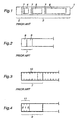
- an ATM cell 1 which comprises a header 2 and a payload 3.
- the payload comprises user data relating to an individual connection.
- an ATM cell is disclosed which in its payload carries one or more mini cells.
- three mini cells 4, 5 and 6 of different sizes are shown.
- Each mini cell 4, 5, 6 comprises a header 7 and user data.
- FIG. 2 an example of a mini cell header 7 is shown to comprise 2 octets 8, 9.
- Other mini cell header sizes are also conceivable depending on the ATM system design.
- a mini cell header size of 3 octets or more are also conceivable.
- the mini cell header 7 comprises a circuit identifier CID, which identifies the established connection/circuit, a payload type selector PTS which identifies different payload types such as user data, control data, maintenance data, a length indicator LEN, and a header integrity check field/bit HIC, which supervises the header integrity.
- the length indicator LEN defines the size of the payload of the individual mini cell.
- Synchronization information The use of the PTS field for this purpose is optional.
- the cell header 7 is shown to comprise a fixed size length field 10, referred to as LEN field, which is used to indicate the size of the user data of the mini cell to which the header belongs.
- the size of the mini cell is indicated in this field 10 using linear coding.
- Linear coding means that the code corresponds to the actual size of the mini cell. For example, if the cell length is 5 octets a binary 5 (000101) is written into the LEN field.
- the fixed length field 10 will occupy much band width but all of the occupied band width is not used for . transmission of useful information as exemplified by the leading zeros in the two examples given. It should be noted that the LEN field 10 is carried by each mini cell of an individual connection.
- a further drawback with this fixed size LEN field 10 is that the range of cell sizes which can be expressed with linear coding is restricted. With a fixed size LEN field 10 comprising 6 bits cell sizes from 1 to 64 octets can be indicated. Should larger cell sizes be used for an individual connection, then the length of the fixed size length field 10 must be enlarged which in turn leads to even more waste of band width.
- Nonlinear coding is used to indicate a wide range of different cell sizes.
- 3 bits are used in an octet, for example octet 9, of a mini cell's header.
- the rest of the bits of the same octet are free and can be used for any of the above listed purposes. This contributes to reduce the overall size of the header which in its turn increases the efficiency with which the band width is used.
- mini cells are generated by voice coders.
- Today the current IS 95 voice coders uses 2, 5, 10 or 22 octets.
- Using the fixed size length field 10 in accordance with said ANSI document 7 bits would be required in the header of the mini cell in order to indicate a cell size of 22 octets.
- With the non-linear coding in accordance with Figure 4 the fixed size length field 11 is 3 bits. This gives a band width saving of 10% for an IS 95 voice coder that operates at 2 kbps (5 octets per 20 ms).
- a mapping table 12 is shown which is to be used together with a fixed size length field 11.
- the code values do not correspond to the mini cells sizes but instead predefined cell sizes are allocated to a respective code value only three code bits are used. Examples of mini cells sizes are given in the size column of the mapping list. The sizes vary from 4 to 60 octets. Of course the range can be increased, but the maximum number of sizes is given by the number of code bits used.
- an extension bit in the fixed size LEN field 11 is used as a qualifier for extension of the LEN field 11 and the method is referred to as the extension bit method, or is one of the length field codes used as qualifier for extension of the LEN field 11 in which case the method is referred to as the extension code method.
- a bit 13, also labeled E, following the LEN field 11 is reserved as an extension bit 13.
- the extension bit 13 When the extension bit 13 is set to 1 this will indicate that the header of the mini cell comprises an extended LEN field 14 of the same size as the fixed size LEN field.
- the extension bit When the extension bit is zero, the cell header comprises the fixed LEN field 11 only.
- the extended length field 14 comprises 3 bits in the illustrated example.
- extension bit 13 When the extension bit 13 is set the number of bits available for the mapping table 12 will increase from 3 to 6 bits leaving a mapping table 15 shown in Figure 7. Since the extension bit 13 is reserved for this purpose it cannot be used for code size mapping purposes.
- a variation of the extension bit method is to append an extension bit 11B to the extended LEN field 14.
- the appended extension field is used to indicate if there is a further extended LEN field in the header in the mini cell or not. If the appended extension bit 11B is set to 1 this indicates that a second extended length field 14A should be added to the header, thus increasing the number of code bits in table 15 from 6 to 9. If the appended extension field comprises a bit which is set to 0 no such second field is used.
- FIG 8 the extension code method is illustrated.
- a code in the fixed length field 11 of Figure 4 is reserved and is used as extension code.
- binary code 111 in mapping table 12 is used as an extension code.
- this code 111 is present in the fixed length field 11 it means that an extended length field 14 should be included in the header of the mini cell. Thus another 3 bits are available for size mapping.
- This method will reduce the number of sizes in mapping table 12 with 1 and will add another seven cell sizes that can be mapped on the additional 8 code values of the extended length field 14.
- extension code method is better than the extension bit method since it requires 3 bits, while the extension bit method requires 4 bits. Looking on the value range the extension bit method is better than the extension code method since it provides 16 different cell sizes compared to 14 as provided by the extension code method.
- the basic format of the mini cell using this combined coding method is shown in Figure 9.
- the mini cell comprises a header 21 of 2 octets and a payload part 22 which may comprise from 1 to 48 octets.
- the four least significant bits of the length of the mini cell is indicated in a small fixed size length field 23, LEN field, in the header.
- the LEN field 23 comprises 4 bits.
- the header also comprises a CID field 24 which occupies 8 bits and which identifies the circuit to which the mini cell belongs. Also in the header there is a length extension qualifier field 25, LEQ field, and a header integrity field 26, HIC field, both 2 bits long.
- the length extension qualifier LEQ 25 is defined as a length extension for the payload and as a header extension.
- LEQ takes the binary codes of 00, 01 and 10 the mini cell has the basic format shown in Figure 9 and the code bits of LEQ constitute bits to be appended to the LEN field 23. In this case the LEQ field will thus serve as an extension of the LEN field 23.
- LEN field 23 is associated to the binary 00 code existing in the LEQ field 25
- 2 4 different values in LEN field 23 is associated with the binary 01 code existing in LEQ field 25
- 2 4 different values in LEN 23 is associated with the binary code 10 existing in LEQ field 25.
- This is illustrated in Figure 10. This gives a total of 48 different length values in accordance with the following general expression: [2 length of LEQ in bits -m] x [2 length of LEN in bite ], where m is the number of codes used to indicate the extended format of the mini cell.
- the payload size can be chosen from forty-eight length values.
- the length values are coded as 1 to 48.
- the LEQ field 25 takes the binary code 11 this signifies that the basic cell format should be extended.
- the extended format is shown in Figure 11.
- the LEQ field 25 has a double meaning.
- the double meaning of LEQ is (i) it is used as the two most significant bits of length indication, i.e. LEQ x 2 4 +LEN as shown in Figure 9 and (ii) it is used as indication of extended header format as shown in Figures 11 and 12, i.e. the LEN field 23 is interpreted as an extension qualifier field 27, EXQ field 27.
- the EXQ field 27 comprises 4 bits.
- the binary values of 0000 and 0001 are reserved for use together with a further length field 29, LENE field, in the manner shown in Figures 12 and 13.
- the least significant bit in EXQ field 27 should be appended to the seven bits in the further LENE field 29 in a manner shown in the dashed rectangle 31 in Figure 13. This is similar to what shown in Figure 10.
- an EXQ value of 0 is used to indicate mini cell lengths varying from 1 to 128 octets and an EXQ value of 1 is used to indicate mini cell lengths varying from 129 to 256 octets.
- An EXQ value of 2 (binary 0010) is used to signify that the mini cell is an operation and maintenance cell, OAM cell, that comprises a header 32, and an OAM information field 33 as shown in Figure 14.
- the header 32 is similar to the header 21 in Figure 12.
- the binary code 11 is present and in the EXQ field 27 the binary code 0010 is present.
- the EXQ code 3 (binary 0011) is used to indicate a fixed length mini cell, for example for the DAMPS system standard. Other EXQ values can be used for other systems standards or services.
- EXQ code values 1xxx are used as synchronization cells; wherein xxx is timing information.
- a main requirement is that the header of the mini cell at the maximum has a length of 2 octets. Given this restriction the available bits are used in an efficient way to cover all ranges of values.
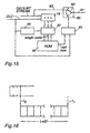
- FIG 15 a block schema of a cell header reading device is shown. It comprises a shift register 19, a first counter 20, a latch register 30, a ROM memory 40, a second counter 50 and a multiplexor 60.
- a bit stream comprising the user data of the mini cells is shifted into shift register 19 at one input thereof.
- a clock signal controls the frequency at which the data bits are shifted into the shift register 19.
- the clock signals are counted by the first counter 20 which is used to extract the fixed size length field 11 of a mini cell and write its data into the register 30.
- the fixed length field or rather the information therein is used as address to the ROM memory 40 which has been configured with the mapping table shown in Figure 5.
- an individual code in the following referred to as length code, will correspond to a specific length of the user data.
- the size of the user data (mini cell size minus the size of the header) is read and is sent to the second counter 50 which controls the multiplexor 60 such that at the output 61 thereof the user data will appear.
- the first counter 20 reads the binary code 011 from the user data channel. This code is used as address to the ROM memory and at this address the cell size 20 is stored. Accordingly the length of the user data should be 20 octets.
- the second counter 50 counts the following 20 octets bit by bit by counting a corresponding number of clock pulses.
- the multiplexor 60 is shown to have an arm 62 which is movable between the indicated two positions. Initially counter 50 sets the arm 62 to the lower position shown with dashed lines and no output data will appear at output 61. when the second counter 50 receives the cell size from the ROM memory 40 it moves arm 62 into the upper position. In the upper position arm 62 connects to a line 63 which in its turn is connected to the input user data channel. When the second counter 50 has counted 20 octets it moves arm 62 back to its initial position and the correct number of octets has now been produced at output 61.
- a predefined number of length codes and cell sizes are stored in ROM 40.
- a RAM memory 70 is used to which length codes and cell sizes are written from a control system 80. In this manner it is possible to configure different specific mini cell sizes for individual mobile telephone systems.
- the mini cell sizes stored in ROM 40 are global in the sense that an individual length code, for example 101, relate to all connections which use mini cells with this length code.
- Figure 18 is a block diagram of a cell header reading device used for implementing the extension code method.
- blocks with the same functions as corresponding blocks in Figures 15 and 17 have the same reference designations.
- the circuit differs from that shown in Figures 15 and 17 in that there is a comparator 90 which is used to detect the extension code. If there is a match, the comparator triggers a subtractor 100 which counts down the first counter 20 by 3 counts. When this has been done the extended length field, or specifically the data therein, is again written into the register 30.
- the various sizes associated with the extended field 14 must be added to the RAM memory 70. This implies that the number of cell sizes in the RAM memory will be doubled. In practice this means that a new memory bank will be used in the RAM memory 70.
- Unit 110 is a D-latch which latches the output value of the comparator 90 and uses it to address the new memory bank, in the RAM memory 70.
- the comparator 90 and the subtractor 100 are the units that will handle the extended length field 14 so that the position in the header will be moved when the extension code is detected. Three extra bits will be added to the length field 11 and it is these extra bits that will be used to indicate the cell length. Accordingly the fixed size length field 11 is replaced with the extended length field 14 which is inserted into the data stream.
- the cell header reading device shown in Figure 18 can also be used in order to implement the extension bit method. This is indicated in Figure 19. From the register 30 that contains the fixed size length field 11 the extension bit 13 is extracted and is used to increase the address range. The extension bit will count down the first counter 20 with three bits, indicated by the subtractor 100. This implies that three new bits will be written into register 30 and these new three bits plus the old three bits, i.e. altogether six bits, are used to address the RAM memory 70 as symbolized by the six arrows. In this manner the number of cell sizes has been increased.
- the ROM memory 40 may have several different mapping tables of the kind shown in Figure 5. It is possible to change from one mapping table to another in response to a predefined length code provided in the header of a mini cell. In this mammer it will be possible to switch from a first set of mini cell lengths, for example 4, 8, 16, 20 to a second set of lengths, for example 3, 6, 9, 12.
- a RAM memory can be used for the same purpose. This will enable the control system 80 to write in new a new set of mini cell lengths in the RAM memory. The whole table can also be transferred in the control message.
- mini cell sizes are mapped on the identities of established connections. Accordingly sizes are not global but connection oriented.
- connection The identity of a connection is given by the CID field of a connection.
- the mini cell header 7 is shown to comprise a CID field 71.
- the actual size of the CID field 71 depends on the system but generally two octets should be sufficient.
- the CID value is used as address to the RAM memory 70 in Figure 17 and is provided by the control system 80. So, instead of latching the length field 11 in the register 30, the CID value is latched in register 30 and is used as address to the RAM memory 70. In this manner there will be a relation between the identity of the established connection and the length of the mini cells used in the connection. Accordingly no additional memory places are needed for storing the relation between a CID and a size of the mini cell associated with said CID.
- the control system 80 will receive a message which requests (a) that a connection should be set up between to identified end points and (b) that this connection shall use mini cells having a size of X octets.
- X is supposed to be an integer selected among the available cell sizes.
- the control system 80 will now use 7 as an address to the RAM memory 70 and will write at this address the mini cell size X.
- the cell header reading device shown in Figure 17 will then operate in the same manner as described. It should be noted that the mapping takes place at connection set-up.
- one and the same CID may relate to several different mini cell sizes depending on the fact that cells having the same CID can be transported on different virtual connections VC:s.
- VC:s virtual connections
- FIG 22 a t:ypical address structure used in an ATM network is shown.
- a physical link referred to as physical route
- VPI/VCI virtual path/virtual identifier
- VC connection identified with an VCI-/VPI value, there is as an example 256 mini cell connections each having its individual CID.
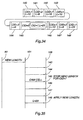
- a specific mini cell is used to indicate the new size in accordance with the methods described in connection with Figures 24-27.
- the new mini cell size is given in the payload 94.
- Four different types are used:
- the new mini cell size to be used for the following mini cells in a connection is indicated in the length field 94. All mini cells following the mini cells 91, 95, 97 in the data stream and having the same CID will have the new cell size and will have their size indicator set to zero thus indicating that the mini cell is used for user data.
- mini cell that comprises information indicative of mini cell size change is, or is not, in sequence with, i.e. linked with, the first mini cell that has the new length in the user data stream. This may or may not give rise to a synchronization problem.
- a mini cell comprising mini cell size change information will in the following be referred to a control mini cell. It should be noted that a control mini cell may comprise, further to mini cell size change information, other information such as user data, control data, OAM data etc.
- the mini cell size should be changed not to frequently, i.e. less frequent than each second, it is proposed in accordance with the present invention to change the size with a control message which is sent over the access protocol between a base station and a controlling node such as for example a mobile switching center MSC.
- the controlling node will be handling and controlling all equipment involved in the establishment of the mini cell connection, in particular the control system 80 in Figures 17, 18 and 19.
- the control message is sent over a channel which is different from that in which mini cells are transported. There will thus be necessary to provide synchronization between the sending end of the mini cells and the receiving end of the same mini cells.
- such synchronization is provided by setting a flag in a bit of the header of a mini cell as indicated in Figure 23 wherein the flag bit is labeled 82.
- Figure 29 shows an embodiment of the cell size change method, in the following referred to as control plane signaling.
- a cell header reading device 83 identical to that shown in Figure 15 receives the user data bit stream 84 transmitted from a symbolically shown sending device 85.
- the control message 86 is sent in a bit stream 87 in a control channel.
- the bit stream 87 is not synchronized with the bit stream 84.
- a protocol handler for signaling messages 88 receives the control message and delivers it to the control system 80.
- the sending device 85 After a sufficient time has lapsed for the control system 80 of the ATM network to process the control message the sending device 85 changes the cell size from L1 to L2 by setting a flag 82 in the first mini cell 89 using the new size L2. This will signal to the receiving side that this cell and the following cells have the new size L2.
- the new length L2 will be read from the mapping table associated with this CID.
- the second counter 50 will thus control multiplexor 60 in such manner that the new cell size will be applied to the mini cell 89 in the shift register 10 and all further cells belonging to this connection. In this manner no information will be lost when the cell size is changed.
- Control plane signaling can trigger cell size changes on a second basis. This is so because the control system 80 has to process control signals which typically takes about 1 ⁇ 2-second. Accordingly control plane signaling is slow and require synchronization.
- Figure 29 is somewhat simplified in order to clearly teach the synchronizing method.
- bit stream 87 is interleaved in bit stream 84 on an irregular time basis.
- a controlling node 100 is a MSC (Mobile Services Switching Center) in a GSM network.
- the controlling node 100 comprises a control system 80 which controls a transmission equipment 101.
- the transmission equipment in its turn comprises a mini cell packetizing device 102 that comprises a cell header reading device 103 of the kind shown in Figures 15, 17, 18 and 19.
- a base station 104 in the GSM network has a similar transmission equipment 105 with a cell depacketizing device 106 that comprises a cell head reading device 107.
- the transmission equipment 101 has a non shown mini cell depacketizing device and the transmission equipment 105 has a non-shown mini cell packetizing device.
- the transmission equipments 101 and 105 are exchanging packets over a link 108.
- Several connections may exist simultaneously but for the sake of the example only one specific connection 109 is considered.
- the mini cells, symbolically shown at 110 and 111, used in the packets for connection 109 are supposed to have a length of 15 octets each. Traffic is supposed to take place continuously on an on-demand basis.
- the control system 80 initiates a change of the size of the mini cells by sending a respective control message 112, 113 to each one of the transmission equipments 101 and 105.
- Each control message indicates that for connection 109 shall the mini cell size shall be changed to a new size of 23 octets.
- no immediate action is taken other than that each equipment now knows that the size is about to be changed to 23 octets. Not until the transmission equipment 105 has information to send it will act. The sequence of operations which then will take place will be described with reference to Figure 31.
- Figure 31 is a signaling diagram showing packets being signaled between transmission equipments 101 and transmission equipment 105.
- the packets are represented by arrows and above the arrows the size of the mini cells used in the packets are shown. Following the arrows in order of time from the top to the bottom the following happens: Initially packets, represented by the two uppermost signal arrows, are exchanged between the transmission equipments 101, 105. The cell length is initially 15 octets. Next the control message 112 is sent to transmission equipment 105. It may also happen that one or more further packets 114 are sent from transmission equipment 101 to transmission equipment 105 before the control message 113 is sent to the transmission equipment 101.
- the receiving transmission equipment 105 will not react on the reception of the control message 112 until it has something to send.
- the next time the transmission equipment 105 has information to send it will send it in a packet 115 in which cells having the new cell length of 23 octets are used.
- a first flag is set in the first cell of the new length.
- This first flag is flag 82 in Figure 29.
- the first flag indicates that this mini cell 115 and the following ones are of the new length.
- the flag is detected by the cell header reading device of the non shown depacketizing device and is used to trig a mechanism that alters the length of the mini cells to be sent in the future from this transmission equipment 101 to the new length.
- This mechanism is resident in the mini cell packetizing device 102.
- transmission equipment 101 When transmission equipment 101 has information to send, it will send it in packets with mini cells of the new length. In the first one, represented by signal arrow 116, of these a second flag is set. Packets which thereafter are exchanged between transmission equipments 101 and 105 will all have the new length as indicated by packets 117 and 118 and will all have no second flag set.
- the first flag in the first mini cell 115 acts as a synchronizing flag.
- the second flag in mini cell 116 acts as an acknowledgment flag that confirms to the transmission equipment 101 that the transmission equipment 105 has received the synchronizing flag.
- connection 109 is in a synchronized state in which both transmission equipments 101 and 105 are sending and receiving packets with the new length. In this manner the length of the mini cells used for a particular connection is changed while the connection remains established.
- control message 112, 113 A control message is typically a separate cell, such as an OAM cell.
- OAM mini cells are sent over a separate connection or in connection 109.
- the use of control messages has no influence of the bandwidth available to the connection 109.
- the mini cell length is to be changed, this will cost only one binary digit, namely the flag bit, of a mini cell. In other words, only one bit needs to be used in the protocol for exchanging information between any two users in the mobile radio system. From bandwidth utilization point of view the control plane signaling method is effective.
- the available mini cell lengths are configured into the mobile radio system.
- the first flag is sent in a mini cell that has the old length of 15 octets. This will give the transmission equipment 101 ample time to instruct its mini cell header reading device to change its settings for reception of cells with the new length.
- control messages 112, 113 are signaled to the sending and receiving side of the particular connection is not specified by method 1.
- a separate control mini cell is required in order to change the size of the mini cells of the connection and a synchronizat:ion mechanism is required in order to make the new mini cell size effective at the right instant.
- This method is an example of method 1 and illustrates how the control message is signaled to the transmission equipments 101, 105.
- a control mini cell is of type 2) above is used.
- the control mini cell is of the type shown in Figure 24 and contains a field 94 containing the new mini cell size.
- the CID value of the control mini cell is different from that of connection 109 the cell size of which is to be changed. Accordingly the control message is sent on a connection which is different from that over which user data is sent.
- connection 109 is active sending packets, which all are filled with mini cells 128 of a length of 15 octets, to transmission equipment 105. At some instant the control system wants to change the mini cell size of the packets in the connection 109 from 15 to 23 octets.
- the control system orders the sending of a control mini cell 127.
- the control mini cell is sent in connection 125.
- the length field 94 the new length 23 is indicated.
- the sending transmission equipment 101 and the receiving transmission equipment 105 will both receive the control mini cell 127, compare the signaling diagram shown in Figure 33, and they will both learn the new length of 23 octets. Any of the two units can now start to use the new length at the next synchronization instant.
- the receiving transmission equipment 105 sets a flag 129 in the first mini cell 130 with the new length it sends in connection 109.
- the transmission equipment 101 When the transmission equipment 101 receives mini cell 130 the cell flag will indicate that the mini cell is formatted with the new length. The transmission equipment 101 will therefore depacketize cell 130 and all following mini cells using the new length of 23 octets. When transmission equipment 101 has anything to sent to the transmission equipment 105 it will use the new length as exemplified by arrow 131.
- next synchronization instant referred to above may occur when a new service is invoked by the control system or when the control system for other reasons want to change the cell size of the particular connection.
- the flag bit acts as a means of synchronization for switching from the old mini cell size to the new mini cell size.
- the synchronization is performed by the sending and receiving units themselves with no help from the control system.
- the transmission equipment first to send sets the synchronization flag when it changes the length of the mini cells it transmits.
- the receiving unit upon reception of the flag, starts to use the new length format.
- the transmission equipment first to send after reception of the control cell 127 is equipment 105. It could as well be transmission equipment 101.
- Method 2 operates quicker than method 1 since the control mini cell contains the new size and therefore the transmission equipment 101, 105 need not await to be contacted by the control system in order to have the new cell size.
- Method 2 has an attractive bandwidth utilization since the overhead in the payload is only one bit each time the size is changed.
- OAM mini cells are handled by the operation and maintenance system of the communication system.
- the OAM mini cells indicating a size change of connection 109 are handled by the terminating transmission equipment 105.
- the control system 80 therefore inserts a control mini cell 145 into the outgoing data stream.
- the transmission equipment 105 reads it and its cell depacketizing device formats it into segments that all are 23 octets long. All of the above method steps are shown in Figure 35.
- the transmission equipment 105 is simple provided the control system 80 allows for cell modification of one connection at a time. If several connections shall change cells size simultaneously the implementation of the transmission equipment 105 will be more complex.
- mini cell size change in accordance with method 3 is handled by the operation and maintenance system and the control message for size change is transported in the traffic flow, that is the flow in which user data mini cells are transported.
- control mini cell is of type 3) above.
- the control mini cell is an OAM mini cell having an EXQ-value of 2 (binary 10).
- the OAM cell shown in Figure 25, has a CID-value equal to that of the connection the cell size of which is to be changed. In other words the OAM cell is transported in the same connection the cell size of which is to be changed. This will ensure that the control mini cell is in the right place in the mini cell flow of the connection the size of which shall be changed. With right place is meant that the control mini cell lies between two mini cells of different sizes which both belong to the connection the mini cell size of which shall be changed. In principle no synchronization mechanism will therefore be required.
- the transmission equipment handle user data mini cells at the traffic plane and they do not handle OAM mini cells.
- OAM mini cells are handled by the operation and maintenance system at the control plane.
- connection 109 shall change size of its mini cells.
- the mini cell size of this connection 109 shall be altered from 15 octets to 23 octets.
- an OAM control mini cell 134 is inserted.
- the OAM control mini cell comprises the new length of 23 octets in its length field 94A ( Figure 25).
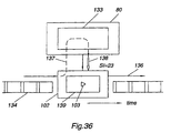
- the control system 80 shown in Figure 36 comprises an OAM mini cell handler 133 and operates on the cell packetizing device 102 with the cell header reading device 103.
- Incoming packets to the cell packetizing device 102 arrive from the left in Figure 36 and outgoing packets leave to the right. As long as incoming mini cells have an EXQ value different from 2 (binary 10) the non shown cell packetizing unit of transmission equipment 105 will packetize them in packets which are sent to their destination along arrow 136.
- the transmission equipment 105 will lift the OAM control mini cell out of the data stream and send it, as indicated by arrow 137, to the control system 80 in which it is treated by the OAM cell handler 133.
- OAM cells may be of many kinds.
- An OAM cell contains a message that indicates to the OAM handler 133 what kind of action to be taken by the control system in response to a received OAM cell. For example it can be a message ordering the control system 80 to measure the error bit rate.
- Another OAM cell may contain a message reporting a hardware malfunction to the control system 80.
- Still another OAM mini cell message is to order the control to test a multitude of mini cells in some respect, for example with regard to a check sum.
- the OAM mini cell 134 is linked to the instant of cell size change and although it belongs to the connection 109 the mini cell size of which is to be changed it appears as if no synchronization is required. This is however not always true.
- the system design may also affect the behavior of method 3. Therefore it might be necessary to provide some synchronization mechanism. Why this is so will be described next.
- the transmission equipment 105 that terminates the connection 109 itself reads the OAM mini cell in order to learn its type. If the OAM mini cell is a cell size modification mini cell the receiving transmission equipment itself will handle the OAM cell and will start to receive and to send mini cells with the new length. This will eliminate the time delay referred to above in connection with interpretation and SI return transmission interval. Still method 3 will ensure that the instant at which the mini cell size is changed will be in correct sequence. In this manner the transmission equipment will ensure that the mini cell size modification cell will be linked to the first mini cell that has the new cell size. Accordinging to this modification of method 3 the OAM cell is handled at the traffic plane.
- control mini cell is transported in the traffic flow and is handled autonomously by the packetizing and depacketizing devices 102, 106.
- the control mini cell is terminated in the traffic plane.
- the loop 137 shown in Figure 36 is eliminated.
- control mini cell is of type 1) above the cell is of the type shown in Figure 26 wherein the CID value of the control cell is the same as that of the connection.
- the method will be described with reference to Figures 37 and 38.
- Figure 37 all units are the same as those described in connection with Figures 30 and 32.
- transmission equipment 101 is sending packets to transmission equipment 105 and that the packets are filled with mini cells 110 having the length of 15 octets.
- the control system 80 orders a change of the length of the cells.
- the new length shall be 23 octets.
- a cell size change order is sent to the transmission equipment 101, for example in an OAM cell.
- the transmission equipment 101 responds to this order by sending a control mini cell 119 of the type shown in Figure 26 to transmission equipment 105. All of, the control mini cell 119 is used for carrying cell size change information.
- the receiving transmission equipment 105 must therefore change the packet size to 23 octets. The question is when.
- the transmission equipment 101 sends the control cell 119 after the last one of the cells 110 of length 15 octets, then all further cells which are sent from the transmission equipment 101 may all have the new length of 23 octets. No additional synchronization will be needed.
- control system 80 may at any time order the sending transmission equipment 101 to change to the new mini cell size.
- FIG. 38 A signaling diagram shown in Figure 38 illustrates the method.
- Figure 38 is similar to Figure 31 and will therefore not be described in detail.
- the order to change mini cell size is indicated by arrow 121.
- the control mini cell is indicated by arrow 122 and has a length of 15 octets. It cannot have the new length.
- the next mini cell 123 sent by the transmission equipment 101 and all mini cells following this are sent with the new size.
- a mechanism, resident in the packetizing device 107 and the non-shown depacketizing device will set the length of the mini cells that follow mini cell 122 to the new length of 23 octets. So when mini cell 123 as sent from the transmission equipment 101 arrives to the transmission equipment 105 it will be decoded with the new length.
- transmission equipment 105 sends its next mini cell 124, it will send it with the new length.
- the bandwidth loss adhering method 4 is proportional to the how often, i.e. the rate or frequency by which, the cell size is modified. It is only in connection with mini cell size change that overhead appears in the form of a control mini cell. Mini cells 110 and 120 contain no fields for cell size indication. Therefore they have no overhead relating to cell size indication. This is in contrast to the mini cells described in connection with Figures 4, 6, 9, 11, 12 which all contain a mini cell size indication.
- Method 4 will result in a complex implementation of the transmission equipment 101, 105 since they must be able to handle a great number of connections simultaneously and in a very short time.
- ATM is a connection oriented technique that defines point-to-point connections. This is in contrast to a packet switched network which is of a connection-less nature. In a packet switched network packets that have the same destination can take different routes through the network and may therefore arrive in reversed time order.
- Method 5 is an improvement of method 4. Instead of using a complete mini cell for changing the size of the mini cells of an ongoing connection an optional field is inserted into a mini cell carrying user data. When the optional field is present it indicates the new size to be used for the mini cells of the connection. In method 5 the information to change size of the mini cells are transported in the traffic flow. According to method 5 a somewhat different message format is used. In principle an explicit, that is separate, length field is used. The method will be described with reference to Figures 39-41.
- a cell size modification mini cell 170 of the type shown in Figure 27 is used.
- An optional field 171 is used to indicate the new length to be used for the mini cells following this cell 170 and belonging to the same connection.
- the connection is indicated by the CID in the header of the mini cell.
- an extension bit 13 ( Figure 27) which when set indicates that the cell contains the optional length field 171. If the extension bit is set to 0 no field 171 is present in the cell 170.
- Method 5 will be described in connection with Figures 39-41.
- Figure 39 is similar to Figures 30 and the same devices are shown.
- the control system 80 will send a cell size modification order 149 to the sending transmission equipment 101 only.
- the sending transmission equipment 101 Upon receipt of the order to change mini cell size the sending transmission equipment 101 sets flag 150, adds the optional length field 171 to the mini cell 170, states the new cell size in the added length field, 23 in the example, sends the mini cell in the new length format of 23 octets and continues to send all further mini cells with the new length.
- transmission equipment 105 Upon reception of the control mini cell 170 transmission equipment 105 detects the flag. In response to the detection of the flag the transmission equipment 105 changes the mini cell size from the current size to the new size indicated in the added optional length field 171. The receiving transmission equipment 105 starts to use the new size of 23 octets, beginning with the control cell and continuing with all of the following cells on this connection.
- Method 5 will save bandwidth since the length field is not present all the time, as is the case with method 4, but is present only when cell size modification is to take place.
- a modification of method 5 is to use the new length format beginning with the mini cell following the mini cell that contains the optional length field 171.
- the old length format is applied to the mini cell that contains the optional length field.
- Methods 2 and 3 are more robust compared to methods 4 and 5 in that they require synchronization. If the control mini cell for some reason is lost, no synchronization will be achieved and no length modification will take place. Information will be transmitted and received with the old cell length and no information will be lost. Synchronization is achieved by sending two mini cells, one in each direction of the connection, comprising synchronizing information. The robustness will be increased but the change rate will be reduced by a factor of 2. In methods 4 and 5 no synchronization is required. If the control cell is lost it will not be received at the receiving side. The transmitting side will change to the new cell size and will start to send the information in cells of the new length. The receiving side will continue to receive cells which it thinks still have the old size. The received information will therefore be corrupted.
- method 5 is slightly inferior to the explicit length method. If, however, the change rate is each second cell, then method 5 is better than the explicate length method. If the change rate is one per each hundred cells, then method 5 is superior to the explicit length method. Method 5 is preferred when the change rate is in the order of one length modification at each ten cells.
- extension bit 13 it is also possible to use a specific payload type selector code, PTS-code, similar to extension code method described in connection with Figure 28 to indicate that the mini cell is used for size change of the following mini cells in the same connection. This is shown in Figure 28.
- a code point in the payload type selector PTS is used for this purpose.
- PTS has a particular code PTSI indicating this.
- FIG 42 there is shown a mobile telephone system comprising an ATM network 200 with a sending unit 201 and a receiving unit 202 are connected via respective link 205 and 206.
- User data sources 203 are connected to the sending unit over a respective connection as shown symbolically by the lines 209.
- User data sinks 204 are connected to the receiving unit 202 over a respective connection 210.
- Connections 209, formed by mini cells, are multiplexed together in the sending unit 201 with a non shown multiplexor.
- demultiplexer in the receiving unit 202 that demultiplexes mini cells belonging to connections which are terminated by the user data sinks 204.
- the sending unit 201 there is a mini cell header reading device 207 of the kind shown in Figure 12 and in the receiving unit there is a similar mini cell header reading device 208 of the kind shown in Figure 12.
- FIG 38 there is shown a mobile telephone system comprising an ATM network 200 with a sending unit 201 and a receiving unit 202 are connected via respective link 205 and 206.
- User data sources 203 are connected to the sending unit over a respective connection as shown symbolically by the lines 209.
- User data sinks 204 are connected to the receiving unit 202 over a respective connection 210.
- Connections 209, formed by mini cells, are multiplexed together in the sending unit 201 with a non shown multiplexor.
- demultiplexor in the receiving unit 202 that demultiplexes mini cells belonging to connections which are terminated by the user data sinks 204.
- the sending unit 201 there is a mini cell header reading device 207 of the kind shown in Figure 11 and in the receiving unit there is a similar mini cell header reading device 208 of the kind shown in Figure 11.
Landscapes
- Engineering & Computer Science (AREA)
- Computer Networks & Wireless Communication (AREA)
- Signal Processing (AREA)
- Computer Security & Cryptography (AREA)
- Data Exchanges In Wide-Area Networks (AREA)
- Mobile Radio Communication Systems (AREA)
- Time-Division Multiplex Systems (AREA)
- Communication Control (AREA)
- Detection And Prevention Of Errors In Transmission (AREA)
- Optical Measuring Cells (AREA)
Claims (19)
- Verfahren zum Anzeigen der Größe einer Minizelle (89), die zu einer einzelnen Verbindung gehört, gekennzeichnet dadurch, dass die Größe nur in Momenten angezeigt wird, wenn sich die Größe der Minizellen der Verbindung zu einer neuen Größe (L2) ändert, und dass nach jedem der Momente die Minizellen (89) der Verbindung mit der neuen Größe (L2) gesendet werden.
- Verfahren gemäß Anspruch 1 zum dynamischen Ändern der Größe einer Minizelle (89) von einer ersten Größe (L1) zu einer zweiten Größe (L2) während einer hergestellten Verbindung, gekennzeichnet dadurch, dass Information, die signalisiert, dass die Größe von Minizellen (89), die für eine einzelne Verbindung verwendet werden, geändert werden soll, in einer Minizelle gesendet wird, die als eine Steuerminizelle bezeichnet wird.
- Verfahren gemäß Anspruch 1 zum dynamischen Ändern der Größe einer Minizelle (89) von einer ersten Größe (L1) zu einer zweiten Größe (L2) während einer hergestellten Verbindung, gekennzeichnet dadurch, dass eine Steuerminizelle in einem Kanal gesendet wird, der sich von dem Kanal unterscheidet, in dem Minizellen (89), die Benutzerdaten der einzelnen Verbindung enthalten, gesendet werden.
- Verfahren gemäß Anspruch 2 zum dynamischen Ändern der Größe einer Minizelle (89) von einer ersten Größe (L1) zu einer zweiten Größe (L2) während einer hergestellten Verbindung, gekennzeichnet dadurch, dass die Änderung einer Minizellengröße einer Synchronisationsprozedur folgend bewirkt wird.
- Verfahren gemäß Anspruch 4 zum dynamischen Ändern der Größe einer Minizelle (89) von einer ersten Größe (L1) zu einer zweiten Größe (L2) während einer hergestellten Verbindung, gekennzeichnet dadurch, dass die Synchronisationsprozedur die folgenden Verfahrensschritte umfasst:eine beliebige einer abschließenden Übertragungsausrüstung (105) und einer veranlassenden Übertragungsausrüstung (101) wird bei Empfang der Steuerminizelle ihre nächste Minizelle (89, 110), gehörend zu der einzelnen Verbindung, mit der zweiten Länge (L2) und mit einem Flag (82), das in dem Header der nächsten Minizelle gesetzt ist, senden,die andere der abschließenden Übertragungsausrüstung (105) und der veranlassenden Übertragungsausrüstung (101) werden bei Empfang der nächsten Minizelle (89, 110) und Erfassung des Flags (82) beginnen, ihre nächste Minizelle zu senden, und alle folgenden, die zu der einzelnen Verbindung gehören, beginnen, Minizellen mit der zweiten Länge (L2) zu senden.
- Verfahren gemäß Anspruch 5 zum dynamischen Ändern der Größe einer Minizelle (89) von einer ersten Größe (L1) zu einer zweiten Größe (L2) während einer hergestellten Verbindung, gekennzeichnet dadurch, dass die Steuerminizelle zu einer Übertragungsausrüstung, die sich auf der veranlassenden Seite der einzelnen Verbindung befindet, ebenso wie zu einer Übertragungsausrüstung, die sich auf der abschließenden Seite der einzelnen Verbindung befindet, gesendet wird.
- Verfahren gemäß Anspruch 5 zum dynamischen Ändern der Größe einer Minizelle (89) von einer ersten Größe (L1) zu einer zweiten Größe (L2) während einer hergestellten Verbindung, gekennzeichnet dadurch, dass die Steuerminizelle eine Betriebs- und Wartungssteuerminizelle ist, die ein Feld enthält, worin die Identität der einzelnen Verbindung angezeigt wird und die zweite Länge angezeigt wird.
- Verfahren gemäß Anspruch 6 zum dynamischen Ändern der Größe einer Minizelle (89) von einer ersten Größe (L1) zu einer zweiten Größe (L2) während einer hergestellten Verbindung, gekennzeichnet dadurch, dass die Steuerminizelle eine Betriebs- und Wartungssteuerminizelle ist, die wenn in der abschließenden Übertragungsausrüstung (105) empfangen wird, zu einem Steuersystem (80) für eine Interpretation gesendet wird, wobei das Steuersystem (80) bei Empfang in der Betriebs- und Wartungszelle und Interpretation davon als eine Minizelle, die die Änderung einer Größe von Minizellen, die zu der Verbindung gehören, signalisiert, die zweite Länge (L2) zu der abschließenden Übertragungsausrüstung (105) sendet, die abschließende Übertragungsausrüstung bei Empfang der zweiten Länge die zweite Länge auf alle weiteren empfangenen Minizellen, die zu der Verbindung gehören, anwendet.
- Verfahren gemäß Anspruch 7 zum dynamischen Ändern der Größe einer Minizelle (89) von einer ersten Größe (L1) zu einer zweiten Größe (L2) während einer hergestellten Verbindung, gekennzeichnet dadurch, dass die Steuerminizelle eine Betriebs- und Wartungssteuerminizelle ist, die wenn in der abschließenden Übertragungsausrüstung (105) empfangen wird, davon als eine Minizelle interpretiert wird, die die Änderung einer Größe von Minizellen (89), die zu der Verbindung gehören, signalisiert, wobei die abschließende Übertragungsausrüstung als Reaktion auf die Interpretation, von der sie die zweite Länge (L2) lernt, die zweite Länge auf alle weiteren empfangenen Minizellen (89), die zu der Verbindung gehören, anwendet.
- Verfahren gemäß Anspruch 2 zum dynamischen Ändern der Größe einer Minizelle (89) von einer ersten Größe (L1) zu einer zweiten Größe (L2) während einer hergestellten Verbindung, gekennzeichnet dadurch, dass die Steuerminizelle in dem gleichen Kanal wie dem gesendet wird, in dem Minizellen (89), die zu der einzelnen Verbindung gehören, gesendet werden.
- Verfahren gemäß Anspruch 2 zum dynamischen Ändern der Größe einer Minizelle (89) von einer ersten Größe (L1) zu einer zweiten Größe (L2) während einer hergestellten Verbindung, gekennzeichnet dadurch, dass die Steuerminizelle in ihrem Header eine Anzeige enthält, die anzeigt, dass die Steuerzelle in ihrer Nutzlast die zweite Länge umfasst.
- Verfahren gemäß Anspruch 10 zum dynamischen Ändern der Größe einer Minizelle (89) von einer ersten Größe (L1) zu einer zweiten Größe (L2) während einer hergestellten Verbindung, gekennzeichnet dadurch, dass eine veranlassende Übertragungsausrüstung (101) zuerst die Steuerminizelle sendet und danach alle weiteren Minizellen (89), die zu der einzelnen Verbindung gehören, mit der zweiten Länge (L2) sendet.
- Verfahren gemäß Anspruch 11 zum dynamischen Ändern der Größe einer Minizelle (89) von einer ersten Größe (L1) zu einer zweiten Größe (L2) während einer hergestellten Verbindung, gekennzeichnet dadurch, dass Übertragungsausrüstung an dem abschließenden Ende der einzelnen Verbindung bei Empfang der Steuerminizelle beginnt, alle weiteren Minizellen, die zu der einzelnen Verbindung gehören, mit der zweiten Länge zu lesen.
- Verfahren gemäß Anspruch 12 zum dynamischen Ändern der Größe einer Minizelle (89) von einer ersten Größe (L1) zu einer zweiten Größe (L2) während einer hergestellten Verbindung, gekennzeichnet dadurch, dass die Steuerminizelle eine Benutzerdatenminizelle ist, die in ihrem Header ein Erweiterungsbit umfasst, das wenn gesetzt anzeigt, dass die Benutzerdatenminizelle ein optionales Feld umfasst, worin die zweite Länge angezeigt wird.
- Verfahren gemäß Anspruch 13 zum dynamischen Ändern der Größe einer Minizelle (89) von einer ersten Größe (L1) zu einer zweiten Größe (L2) während einer hergestellten Verbindung, gekennzeichnet dadurch, dass eine Steuernachricht, die eine Zellengrößenmodifikation anzeigt, gesendet wird, und dass diesem folgend ein Synchronisationssignal gesendet wird.
- Verfahren zum Ändern der Größe einer Minizelle (89, 110) von einer ersten Größe (L1) zu einer zweiten Größe (L2) gemäß Anspruch 14, worin Minizellen, die zu der gleichen Verbindung gehören, in einem Benutzerdatenkanal transportiert werden, gekennzeichnet dadurch, dass eine Steuernachricht (112) die zweite Größe und die Identität der Verbindung umfasst, dass die Steuernachricht von einer Basisstation zu einem Steuersystem über einen Steuerkanal unter Verwendung eines Zugriffsprotokolls gesendet wird, dass das Steuersystem die zweite Zellengröße mit Minizellen, die zu der Verbindung gehören, assoziiert, dass ein Zellenlängenmodifikationsindikator, der als das Synchronisationssignal verwendet wird, in der ersten Minizelle mit der neuen zweiten Größe gesetzt ist, dass das Steuersystem bei Erfassung des Zellenlängenmodifikationsindikators in der ersten Minizelle die Größe der Minizellen, die zu der Verbindung gehören, von der ersten zu der zweiten Größe ändert.
- Verfahren gemäß Anspruch 1 zum Ändern der Größe einer Minizelle (89) von einer ersten Größe (L1) zu einer zweiten Größe (L2) während einer hergestellten Verbindung, worin eine Betriebs- und Wartungsverbindung allen Verbindungen gemeinsam ist und eine vordefinierte erste Verbindungsidentität hat, wobei die Betriebs- und Wartungsverbindung durch Betriebs- und Wartungszellen, OAM-Zellen, mit der vordefinierten ersten Verbindungsidentität ausgeführt wird, gekennzeichnet durch Versehen einer OAM-Zelle mit einer Identifikation einer Verbindung, deren Bandbreite zu ändern ist, ebenso wie mit Information über die zweite Größe.
- Verfahren gemäß Anspruch 1 zum Ändern der Größe einer Minizelle (89) von einer ersten Größe (L1) zu einer zweiten Größe (L2) während einer hergestellten Verbindung, worin eine Ressourcenmanagementverbindung allen Verbindungen gemeinsam ist und eine vordefinierte erste Verbindungsidentität hat, wobei die Ressourcenmanagementverbindung durch Ressourcenmanagementzellen ausgeführt wird, mit der vordefinierten ersten Verbindungsidentität, gekennzeichnet durch Versehen einer Ressourcenmanagementzelle mit einer Identifikation einer Verbindung, deren Bandbreite zu ändern ist, ebenso wie mit Information über die zweite Größe.
- Verfahren gemäß Anspruch 1 zum Ändern der Größe einer Minizealle (89) von einer ersten Größe (L1) zu einer zweiten Größe (L2) während einer hergestellten Verbindung, gekennzeichnet dadurch, dass eine größenmodifizierende Minizelle in dem Benutzerdatenkanal in Synchronismus mit den Minizellen darin gesendet wird.
Applications Claiming Priority (3)
| Application Number | Priority Date | Filing Date | Title |
|---|---|---|---|
| SE9600279A SE515588C2 (sv) | 1996-01-25 | 1996-01-25 | Miniceller med variabel för storlek på nyttolasten i ett mobiltelefonnät |
| SE9600279 | 1996-01-25 | ||
| PCT/SE1997/000118 WO1997027691A1 (en) | 1996-01-25 | 1997-01-24 | A method of indicating mini cell size |
Publications (2)
| Publication Number | Publication Date |
|---|---|
| EP0872093A1 EP0872093A1 (de) | 1998-10-21 |
| EP0872093B1 true EP0872093B1 (de) | 2004-10-20 |
Family
ID=20401152
Family Applications (2)
| Application Number | Title | Priority Date | Filing Date |
|---|---|---|---|
| EP97901894A Ceased EP0876723A1 (de) | 1996-01-25 | 1997-01-24 | Minizellen mit variabler nutzlastgrösse |
| EP97901895A Expired - Lifetime EP0872093B1 (de) | 1996-01-25 | 1997-01-24 | Verfahren zur angabe der grösse von minizellen |
Family Applications Before (1)
| Application Number | Title | Priority Date | Filing Date |
|---|---|---|---|
| EP97901894A Ceased EP0876723A1 (de) | 1996-01-25 | 1997-01-24 | Minizellen mit variabler nutzlastgrösse |
Country Status (12)
| Country | Link |
|---|---|
| US (3) | US6341131B1 (de) |
| EP (2) | EP0876723A1 (de) |
| JP (2) | JP3857728B2 (de) |
| KR (2) | KR19990081936A (de) |
| CN (2) | CN1124723C (de) |
| AU (2) | AU724864B2 (de) |
| BR (2) | BR9707061A (de) |
| CA (2) | CA2243172A1 (de) |
| DE (1) | DE69731276T2 (de) |
| RU (2) | RU2178624C2 (de) |
| SE (4) | SE515588C2 (de) |
| WO (2) | WO1997027691A1 (de) |
Families Citing this family (63)
| Publication number | Priority date | Publication date | Assignee | Title |
|---|---|---|---|---|
| GB9621776D0 (en) * | 1996-10-18 | 1996-12-11 | Northern Telecom Ltd | ATM communications system and method |
| GB9624917D0 (en) * | 1996-11-29 | 1997-01-15 | Northern Telecom Ltd | Distribution network |
| GB2322515A (en) * | 1997-02-21 | 1998-08-26 | Northern Telecom Ltd | Adaptation layer switching |
| GB2322516A (en) * | 1997-02-21 | 1998-08-26 | Northern Telecom Ltd | Multimedia switching system |
| GB2322514A (en) * | 1997-02-21 | 1998-08-26 | Northern Telecom Ltd | Telecommunications system |
| US7894936B2 (en) * | 1997-10-09 | 2011-02-22 | Walker Digital, Llc | Products and processes for managing the prices of vending machine inventory |
| DE19818776A1 (de) * | 1998-04-27 | 1999-11-04 | Siemens Ag | Verfahren zur Verbindung von Kommunikationssystemen über eine paketorientierte Datenübertragungsstrecke |
| WO2000021246A1 (en) * | 1998-10-05 | 2000-04-13 | Nokia Netwoks Oy | Frame control method and apparatus |
| DE69832186T2 (de) * | 1998-12-23 | 2006-07-13 | Alcatel | Verfahren und Vorrichtung zur Erzeugung von Datenzellen und Anordnung zum Empfang von Datenzellen |
| JP2000341300A (ja) * | 1999-05-31 | 2000-12-08 | Fujitsu Ltd | Atmネットワークに於けるセル多重化システム |
| US6804237B1 (en) * | 1999-06-23 | 2004-10-12 | Nortel Networks Limited | Method, devices and signals for multiplexing payload data for transport in a data network |
| GB9915327D0 (en) * | 1999-06-30 | 1999-09-01 | Nortel Networks Corp | Packet interface and method of packetizing information |
| GB2356100B (en) * | 1999-11-05 | 2004-02-25 | Sony Uk Ltd | Data format and data transfer |
| DE69926514T2 (de) * | 1999-11-23 | 2006-06-08 | Lucent Technologies Inc. | Verfahren, Vorrichtung und Datenpaket zum Anzeigen der Länge der Nutzdaten, die in einem Datenpaket in einem Mobilfunktnetz übermittelt werden |
| US7730201B1 (en) * | 2000-04-13 | 2010-06-01 | Alcatel-Lucent Canada, Inc. | Method and apparatus for congestion avoidance in source routed signaling protocol communication networks |
| US7224693B1 (en) * | 2000-08-11 | 2007-05-29 | Ericsson Ab | Long packet handling |
| FR2818066B1 (fr) * | 2000-12-12 | 2003-10-10 | Eads Airbus Sa | Procede et dispositif de transmission deterministe de donnees asynchrones mises en paquet |
| US7190685B2 (en) * | 2001-02-08 | 2007-03-13 | Lucent Technologies Inc. | Control information transmission in a wireless communication system |
| US7369555B2 (en) * | 2001-07-31 | 2008-05-06 | Telefonaktiebolaget Lm Ericsson (Publ) | Channel resource allocation arrangement and method |
| JP3771238B2 (ja) * | 2002-03-04 | 2006-04-26 | 三菱電機株式会社 | 多重化伝送装置 |
| EP2385665A1 (de) | 2002-03-08 | 2011-11-09 | Aware, Inc. | System und Verfahren für OFDM-Kommunikationen unter Verwendung von verschiedenen längen des zyklischen Präfix |
| US7047001B2 (en) * | 2002-12-02 | 2006-05-16 | Qualcomm Inc. | Method and apparatus for mobile-terminated short data burst communication |
| US7113790B2 (en) * | 2003-02-18 | 2006-09-26 | Qualcomm Incorporated | Method and apparatus for using a traffic channel for communications of control data in a wireless communication system |
| WO2004075582A1 (en) * | 2003-02-21 | 2004-09-02 | Nortel Networks Limited | Data communication apparatus and method for establishing a codec-bypass connection |
| TWI271626B (en) * | 2003-06-17 | 2007-01-21 | Delta Electronics Inc | Data transmission method for microprocessors of programmable logic controller |
| US7260400B2 (en) * | 2004-03-05 | 2007-08-21 | Samsung Electronics Co., Ltd. | Method and apparatus for transmitting and receiving control message in wireless access communication system |
| AU2005222291B2 (en) | 2004-03-12 | 2008-07-17 | Samsung Electronics Co., Ltd. | Method and apparatus for constructing map ie using reduced CID in broadband OFDMA systems |
| US8027265B2 (en) * | 2004-03-19 | 2011-09-27 | Genband Us Llc | Providing a capability list of a predefined format in a communications network |
| WO2005089055A2 (en) * | 2004-03-19 | 2005-09-29 | Nortel Networks Limited | Communicating processing capabilites along a communications path |
| US7580388B2 (en) | 2004-06-01 | 2009-08-25 | Lg Electronics Inc. | Method and apparatus for providing enhanced messages on common control channel in wireless communication system |
| WO2006001650A1 (en) | 2004-06-23 | 2006-01-05 | Samsung Electronics Co., Ltd. | Method of configuring and updating connection identifier in a broadband wireless access communication system |
| US8000221B2 (en) | 2004-07-20 | 2011-08-16 | Qualcomm, Incorporated | Adaptive pilot insertion for a MIMO-OFDM system |
| US7529218B2 (en) * | 2004-08-25 | 2009-05-05 | Cisco Technology, Inc. | High density WLAN system |
| US7830864B2 (en) * | 2004-09-18 | 2010-11-09 | Genband Us Llc | Apparatus and methods for per-session switching for multiple wireline and wireless data types |
| US7729346B2 (en) | 2004-09-18 | 2010-06-01 | Genband Inc. | UMTS call handling methods and apparatus |
| CN101133658A (zh) * | 2004-10-22 | 2008-02-27 | 特克雷克公司 | 移动性管理设备及方法 |
| US8189615B2 (en) * | 2004-12-23 | 2012-05-29 | Nokia Corporation | Method and apparatus for communicating scheduling information from a UE to a radio access network |
| EP1832143B1 (de) * | 2004-12-30 | 2015-04-29 | LG Electronics Inc. | Verfahren und vorrichtung zur aktualisierung durch eine mobilstation von kanalinformationen in einem funkruf nicht verfügbaren zeitintervall |
| US8483173B2 (en) | 2005-05-31 | 2013-07-09 | Genband Us Llc | Methods and systems for unlicensed mobile access realization in a media gateway |
| US7792150B2 (en) | 2005-08-19 | 2010-09-07 | Genband Us Llc | Methods, systems, and computer program products for supporting transcoder-free operation in media gateway |
| US7835346B2 (en) * | 2006-01-17 | 2010-11-16 | Genband Us Llc | Methods, systems, and computer program products for providing transcoder free operation (TrFO) and interworking between unlicensed mobile access (UMA) and universal mobile telecommunications system (UMTS) call legs using a media gateway |
| US8059681B2 (en) * | 2006-05-02 | 2011-11-15 | Samsung Electronics Co., Ltd. | Method and apparatus for transmitting/receiving packet in mobile communication system |
| US8346239B2 (en) | 2006-12-28 | 2013-01-01 | Genband Us Llc | Methods, systems, and computer program products for silence insertion descriptor (SID) conversion |
| US8619730B2 (en) * | 2007-07-20 | 2013-12-31 | Broadcom Corporation | Method and system for establishing a connection outside a mesh by including network connectivity information in router configuration messages |
| US8274957B2 (en) | 2007-07-20 | 2012-09-25 | Broadcom Corporation | Method and system for dynamically setting up and tearing down connections in mesh networks |
| US8422411B2 (en) * | 2007-10-07 | 2013-04-16 | Motorola Mobility Llc | Flexible frame structure in wireless communication system |
| US9118465B2 (en) * | 2008-02-21 | 2015-08-25 | Google Technology Holdings LLC | Method for supporting flexible frame structures in wireless communication systems |
| JP5315542B2 (ja) * | 2008-10-03 | 2013-10-16 | 日立コンシューマエレクトロニクス株式会社 | コンテンツ送信方法及びコンテンツ送信装置、コンテンツ受信方法及びコンテンツ受信装置 |
| US8108546B2 (en) * | 2008-12-12 | 2012-01-31 | Comtech Ef Data Corporation | Data packet encapsulation methods |
| KR101147777B1 (ko) | 2009-04-14 | 2012-05-25 | 엘지전자 주식회사 | 매체접속제어 프로토콜데이터 유닛 전송방법 |
| CN101574494B (zh) * | 2009-06-17 | 2010-06-23 | 张淑芬 | 一种治疗乙肝的药物 |
| EP2446600B1 (de) | 2009-06-25 | 2016-09-28 | Koninklijke Philips N.V. | Verfahren und gerät zum bearbeiten von daten paketen |
| KR101646942B1 (ko) * | 2009-07-13 | 2016-08-09 | 삼성전자주식회사 | 매체 접속 제어 프로토콜 데이터 유닛의 길이 정보의 인코딩 및 디코딩을 위한 방법 및 시스템 |
| US8908541B2 (en) | 2009-08-04 | 2014-12-09 | Genband Us Llc | Methods, systems, and computer readable media for intelligent optimization of digital signal processor (DSP) resource utilization in a media gateway |
| WO2011030957A1 (en) | 2009-09-09 | 2011-03-17 | Lg Electronics Inc. | Method and apparatus of scanning channels in wireless local area network |
| JP5688089B2 (ja) | 2009-10-21 | 2015-03-25 | エルジー エレクトロニクス インコーポレイティド | TVWS(TVWhiteSpace)で存在するネットワークをスキャニングするための方法及び装置 |
| CN102792738B (zh) | 2010-03-12 | 2016-01-20 | Lg电子株式会社 | Wlan系统中保护主服务的方法和设备 |
| US8583129B2 (en) | 2010-03-19 | 2013-11-12 | Lg Electronics Inc. | Method and apparatus for acquiring available channel information in a wireless local area network system |
| WO2011145796A1 (en) | 2010-05-18 | 2011-11-24 | Lg Electronics Inc. | Method and apparatus for dynamic station enablement procedure in a wireless local area network system |
| CN103039021B (zh) | 2010-06-07 | 2015-11-25 | Lg电子株式会社 | 用于站在wlan系统内工作的方法和装置 |
| US8743493B1 (en) | 2013-01-16 | 2014-06-03 | Lsi Corporation | Fixed-point processing using quantization levels based on floating-point processing |
| KR20190124347A (ko) * | 2013-07-05 | 2019-11-04 | 새턴 라이센싱 엘엘씨 | 송신 장치 및 송신 방법, 및 수신 장치 및 수신 방법 |
| US11595846B2 (en) | 2018-04-19 | 2023-02-28 | Telefonaktiebolaget Lm Ericsson (Publ) | Apparatuses and methods for handling data packets |
Family Cites Families (30)
| Publication number | Priority date | Publication date | Assignee | Title |
|---|---|---|---|---|
| JPS5819061A (ja) | 1981-07-27 | 1983-02-03 | Nippon Telegr & Teleph Corp <Ntt> | 制御信号デ−タ拡張法 |
| JPS58181392A (ja) | 1982-04-16 | 1983-10-24 | Meidensha Electric Mfg Co Ltd | 符号伝送方法 |
| US4691314A (en) * | 1985-10-30 | 1987-09-01 | Microcom, Inc. | Method and apparatus for transmitting data in adjustable-sized packets |
| EP0809381B1 (de) * | 1988-07-22 | 2004-11-24 | Hitachi, Ltd. | ATM-Vermittlungssystem |
| FR2635242B1 (fr) * | 1988-08-05 | 1990-10-05 | Lmt Radio Professionelle | Procede et dispositif de transmission en mode asynchrone mettant en oeuvre des microcellules |
| EP0365693B1 (de) * | 1988-09-23 | 1993-11-18 | Siemens Aktiengesellschaft | Verfahren und Schaltungsanordnung zum Übertragen von Nachrichtensignalen in einem Breitband-Kommunikationsnetz |
| US5020055A (en) * | 1989-06-23 | 1991-05-28 | May Jr Carl J | Multi-length packet format including fixed length information words |
| WO1992013395A1 (en) * | 1991-01-28 | 1992-08-06 | Motorola, Inc. | Receiver controller method and apparatus |
| AU647267B2 (en) * | 1991-05-07 | 1994-03-17 | Fujitsu Limited | Switching node in label multiplexing type switching network |
| EP0528085A1 (de) * | 1991-08-19 | 1993-02-24 | Siemens Aktiengesellschaft | Fernmeldenetz mit ATM- und STM-Vermittlung |
| EP0528087A1 (de) * | 1991-08-19 | 1993-02-24 | Siemens Aktiengesellschaft | Verfahren und Anordnung zur Übermittlung von STM-vermittelten Nachrichten über ATM-Vermittlungsstellen |
| FR2685592B1 (fr) * | 1991-12-18 | 1994-03-18 | Alcatel Nv | Procede et un systeme de transmission d'information sur une liaison de transmission par blocs de donnees de longueur variable en multiplexage temporel de type asynchrone. |
| US5274642A (en) * | 1992-06-05 | 1993-12-28 | Indra Widjaja | Output buffered packet switch with a flexible buffer management scheme |
| US5550802A (en) * | 1992-11-02 | 1996-08-27 | National Semiconductor Corporation | Data communication network with management port for isochronous switch |
| US5333135A (en) * | 1993-02-01 | 1994-07-26 | North American Philips Corporation | Identification of a data stream transmitted as a sequence of packets |
| DE69330675T2 (de) * | 1993-06-03 | 2002-06-13 | International Business Machines Corp., Armonk | Verbesserte Paketstruktur für Netzschicht |
| DE4326377C2 (de) * | 1993-08-05 | 1998-12-17 | Siemens Ag | Modifiziertes frame-relay-Übertragungsverfahren |
| JP3405800B2 (ja) * | 1994-03-16 | 2003-05-12 | 富士通株式会社 | Atmによる可変長セルの転送方式,atmによる可変長セルのスイッチ及びatmによる可変長セルの交換機 |
| SE503317C2 (sv) * | 1994-06-13 | 1996-05-13 | Ericsson Telefon Ab L M | Sätt och väljarnod för att koppla STM-celler i en kretsemulerad ATM-väljare |
| US5583859A (en) * | 1994-08-30 | 1996-12-10 | Bell Communications Research, Inc. | Data labeling technique for high performance protocol processing |
| US5481544A (en) * | 1994-10-17 | 1996-01-02 | At&T Corp. | Multi-channel broadband adaptation processing |
| US5606552A (en) * | 1994-10-17 | 1997-02-25 | Lucent Technologies Inc. | Broadband adaptation processing |
| US5541919A (en) * | 1994-12-19 | 1996-07-30 | Motorola, Inc. | Multimedia multiplexing device and method using dynamic packet segmentation |
| SE505845C2 (sv) * | 1995-04-24 | 1997-10-13 | Ericsson Telefon Ab L M | Telekommunikationssystem och sätt att överföra mikroceller i detta |
| US5675591A (en) * | 1995-08-31 | 1997-10-07 | Motorola, Inc. | Reverse checksum method for telecommunication systems |
| KR970707658A (ko) * | 1995-09-12 | 1997-12-01 | 요트. 게. 아. 롤페즈 | 동기성 및 비동기성 데이터부 전송 시스템(Transmission system for synchronous and asynchronous data portions) |
| US5742610A (en) * | 1996-02-06 | 1998-04-21 | Motorola, Inc. | Method and apparatus for use in a data communications network serving subscribers operating at a plurality of transmisson data rates |
| US5822321A (en) * | 1996-04-10 | 1998-10-13 | Telefonaktiebolaget Lm Ericsson | Minicell segmentation and reassembly |
| US5802050A (en) * | 1996-06-10 | 1998-09-01 | Telefonaktiebolaget Lm Ericsson | Minicell sequence number count |
| GB9621776D0 (en) * | 1996-10-18 | 1996-12-11 | Northern Telecom Ltd | ATM communications system and method |
-
1996
- 1996-01-25 SE SE9600279A patent/SE515588C2/sv not_active IP Right Cessation
-
1997
- 1997-01-24 AU AU15638/97A patent/AU724864B2/en not_active Ceased
- 1997-01-24 WO PCT/SE1997/000118 patent/WO1997027691A1/en not_active Ceased
- 1997-01-24 DE DE69731276T patent/DE69731276T2/de not_active Expired - Lifetime
- 1997-01-24 EP EP97901894A patent/EP0876723A1/de not_active Ceased
- 1997-01-24 BR BR9707061A patent/BR9707061A/pt active Search and Examination
- 1997-01-24 KR KR1019980705652A patent/KR19990081936A/ko not_active Abandoned
- 1997-01-24 WO PCT/SE1997/000117 patent/WO1997027690A1/en not_active Ceased
- 1997-01-24 JP JP52679197A patent/JP3857728B2/ja not_active Expired - Lifetime
- 1997-01-24 EP EP97901895A patent/EP0872093B1/de not_active Expired - Lifetime
- 1997-01-24 JP JP9526790A patent/JP2000504163A/ja active Pending
- 1997-01-24 BR BR9707066A patent/BR9707066A/pt unknown
- 1997-01-24 RU RU98115888/09A patent/RU2178624C2/ru active
- 1997-01-24 CN CN97193089A patent/CN1124723C/zh not_active Expired - Fee Related
- 1997-01-24 CA CA002243172A patent/CA2243172A1/en not_active Abandoned
- 1997-01-24 CN CN97193288A patent/CN1214830A/zh active Pending
- 1997-01-24 AU AU15639/97A patent/AU734354B2/en not_active Ceased
- 1997-01-24 CA CA002242338A patent/CA2242338C/en not_active Expired - Fee Related
- 1997-01-24 KR KR10-1998-0705712A patent/KR100363210B1/ko not_active Expired - Fee Related
- 1997-01-24 RU RU98115844/09A patent/RU2178623C2/ru active
- 1997-01-27 US US08/789,534 patent/US6341131B1/en not_active Expired - Lifetime
- 1997-01-27 US US08/789,479 patent/US6631116B1/en not_active Expired - Lifetime
- 1997-11-28 SE SE9704408A patent/SE518261C2/sv not_active IP Right Cessation
- 1997-11-28 SE SE9704407A patent/SE9704407D0/xx not_active Application Discontinuation
- 1997-11-28 SE SE9704409A patent/SE9704409D0/xx not_active Application Discontinuation
-
2001
- 2001-10-23 US US09/983,092 patent/US7054318B2/en not_active Expired - Fee Related
Also Published As
Similar Documents
| Publication | Publication Date | Title |
|---|---|---|
| US6631116B1 (en) | Method of indicating mini cell size | |
| US5119367A (en) | Method and a node circuit for routing bursty data | |
| US5481544A (en) | Multi-channel broadband adaptation processing | |
| US5936967A (en) | Multi-channel broadband adaptation processing | |
| US6253207B1 (en) | Method and apparatus for transporting multimedia information over heterogeneous wide area networks | |
| EP0886988B1 (de) | System für drahtgebundene und drahtlose übertragungen zur unterstutzung des zugriffs zu nach dem asynchronen transfer modus und mit variabeler bandbreite arbeitenden netzwerken | |
| EP0649234B1 (de) | Verfahren und Einrichtung zum Datentransfer in ein ATM-Netz | |
| US5606552A (en) | Broadband adaptation processing | |
| EP0995290B1 (de) | Vc-zusammenstellung für eine atm-vermittlungstelle | |
| EP0781008A1 (de) | Verfahren und System zur Kombination von Verbindungen über ein ATM-Netzwerk | |
| EP0982967A2 (de) | Vorrichtung und Verfahren zum Multiplexen von ATM Zellen | |
| US8009679B2 (en) | Communication system and method | |
| EP1946498B1 (de) | Kommunikationssystem und verfahren | |
| CA2270100A1 (en) | Method for connecting communication systems via a packet-oriented data transmission link | |
| KR19980017792A (ko) | Aal 타입 1에서의 구조적 데이터 전달정보를 갖춘 포인터로부터의 경계신호 추출장치 및 그 추출방법 | |
| KR19980017785A (ko) | Aal 타입 1에서의 구조적 데이터 전달을 위한 포인터 발생장치 및 그 발생방법 | |
| AU4890900A (en) | Mini cells with variable payload size | |
| KR19980017783A (ko) | Aal 타입 1에서의 고정비트율 데이터 처리장치에 있어서 구조적 데이터 전달방법 | |
| KR19980017800A (ko) | Aal 타입 1에서의 구조적 데이터 전달을 위한 포인터 발생장치 및 그 발생방법 | |
| KR19980017786A (ko) | Aal 타입 1에서의 구조적 데이터 전달정보를 갖춘 포인터로부터의 경계신호 추출장치 및 그 추출방법 |
Legal Events
| Date | Code | Title | Description |
|---|---|---|---|
| PUAI | Public reference made under article 153(3) epc to a published international application that has entered the european phase |
Free format text: ORIGINAL CODE: 0009012 |
|
| 17P | Request for examination filed |
Effective date: 19980629 |
|
| AK | Designated contracting states |
Kind code of ref document: A1 Designated state(s): DE ES FR GB IT SE |
|
| 17Q | First examination report despatched |
Effective date: 20031117 |
|
| GRAP | Despatch of communication of intention to grant a patent |
Free format text: ORIGINAL CODE: EPIDOSNIGR1 |
|
| RAP1 | Party data changed (applicant data changed or rights of an application transferred) |
Owner name: TELEFONAKTIEBOLAGET LM ERICSSON (PUBL) |
|
| GRAS | Grant fee paid |
Free format text: ORIGINAL CODE: EPIDOSNIGR3 |
|
| GRAA | (expected) grant |
Free format text: ORIGINAL CODE: 0009210 |
|
| AK | Designated contracting states |
Kind code of ref document: B1 Designated state(s): DE ES FR GB IT SE |
|
| PG25 | Lapsed in a contracting state [announced via postgrant information from national office to epo] |
Ref country code: IT Free format text: LAPSE BECAUSE OF FAILURE TO SUBMIT A TRANSLATION OF THE DESCRIPTION OR TO PAY THE FEE WITHIN THE PRESCRIBED TIME-LIMIT;WARNING: LAPSES OF ITALIAN PATENTS WITH EFFECTIVE DATE BEFORE 2007 MAY HAVE OCCURRED AT ANY TIME BEFORE 2007. THE CORRECT EFFECTIVE DATE MAY BE DIFFERENT FROM THE ONE RECORDED. Effective date: 20041020 Ref country code: FR Free format text: LAPSE BECAUSE OF FAILURE TO SUBMIT A TRANSLATION OF THE DESCRIPTION OR TO PAY THE FEE WITHIN THE PRESCRIBED TIME-LIMIT Effective date: 20041020 |
|
| REG | Reference to a national code |
Ref country code: GB Ref legal event code: FG4D |
|
| REF | Corresponds to: |
Ref document number: 69731276 Country of ref document: DE Date of ref document: 20041125 Kind code of ref document: P |
|
| PG25 | Lapsed in a contracting state [announced via postgrant information from national office to epo] |
Ref country code: SE Free format text: LAPSE BECAUSE OF FAILURE TO SUBMIT A TRANSLATION OF THE DESCRIPTION OR TO PAY THE FEE WITHIN THE PRESCRIBED TIME-LIMIT Effective date: 20050120 |
|
| PG25 | Lapsed in a contracting state [announced via postgrant information from national office to epo] |
Ref country code: ES Free format text: LAPSE BECAUSE OF FAILURE TO SUBMIT A TRANSLATION OF THE DESCRIPTION OR TO PAY THE FEE WITHIN THE PRESCRIBED TIME-LIMIT Effective date: 20050131 |
|
| PLBE | No opposition filed within time limit |
Free format text: ORIGINAL CODE: 0009261 |
|
| STAA | Information on the status of an ep patent application or granted ep patent |
Free format text: STATUS: NO OPPOSITION FILED WITHIN TIME LIMIT |
|
| 26N | No opposition filed |
Effective date: 20050721 |
|
| EN | Fr: translation not filed | ||
| PGFP | Annual fee paid to national office [announced via postgrant information from national office to epo] |
Ref country code: DE Payment date: 20140129 Year of fee payment: 18 |
|
| PGFP | Annual fee paid to national office [announced via postgrant information from national office to epo] |
Ref country code: GB Payment date: 20140127 Year of fee payment: 18 |
|
| REG | Reference to a national code |
Ref country code: DE Ref legal event code: R119 Ref document number: 69731276 Country of ref document: DE |
|
| GBPC | Gb: european patent ceased through non-payment of renewal fee |
Effective date: 20150124 |
|
| PG25 | Lapsed in a contracting state [announced via postgrant information from national office to epo] |
Ref country code: DE Free format text: LAPSE BECAUSE OF NON-PAYMENT OF DUE FEES Effective date: 20150801 Ref country code: GB Free format text: LAPSE BECAUSE OF NON-PAYMENT OF DUE FEES Effective date: 20150124 |